Embed Size (px)
Citation preview
© 2004 - 2007 © 2004 - 2010 9000 Virginia Manor Rd Ste 290, Beltsville MD 20705 | 301-474-0607 | www.dfrsolutions.com © 2004 – 2010
Effective Reliability Test Plan Development using Physics of
Failure
Greg Caswell

© 2004 - 2007 © 2004 - 2010 9000 Virginia Manor Rd Ste 290, Beltsville MD 20705 | 301-474-0607 | www.dfrsolutions.com
Introduction
o Agenda
o Introduction to Test Plan Development
o Introduction to Physics of Failure Methodology for Test Plan
Development
o Virtual Qualification Option
o After Release
o Case Study Power Cycling
Vibration
Temperature/
Humidity
Mechanical Shock
Temperature Cycling

© 2004 - 2007 © 2004 - 2010 9000 Virginia Manor Rd Ste 290, Beltsville MD 20705 | 301-474-0607 | www.dfrsolutions.com
o How can you be sure that you have the best test plans
for your specific need?
o DfR Solutions has worked closely with over 500 OEMs
in multiple industries developing hundreds (thousands??)
of test plans.
o DfR Solutions experts have written product specs for these
organizations.
o Through close collaboration with industry leading
electronics manufacturers and deep industry
knowledge, DfR Solutions delivers the right test for the
right product every time!
Test Plan Development
© 2004 - 2007 © 2004 - 2010 9000 Virginia Manor Rd Ste 290, Beltsville MD 20705 | 301-474-0607 | www.dfrsolutions.com
Test Plan Development
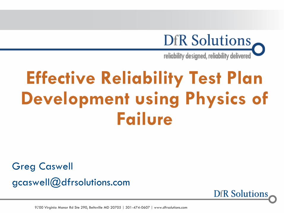
o Product test plans are critical to the success of a new product or technology
o Stressful enough to identify defects
o Show correlation to a realistic environment
o DfR Solutions approach
o Industry Standards + Physics of Failure
o Results in an optimized test plan that is acceptable to management and customers
• MIL-STD-810,
• MIL-HDBK-310,
• SAE J1211,
• IPC-SM-785,
• Telcordia GR3108,
• IEC 60721-3, etc.
• PoF!

© 2004 - 2007 © 2004 - 2010 9000 Virginia Manor Rd Ste 290, Beltsville MD 20705 | 301-474-0607 | www.dfrsolutions.com
o PoF Definition: The use of science (physics, chemistry, etc.)
to capture an understanding of failure mechanisms and
evaluate useful life under actual operating conditions
o Using PoF, design, perform, and interpret the results of
accelerated life tests
o Starting at design stage
o Continuing throughout the lifecycle of the product
o Start with standard industry specifications
o Modify or exceed them
o Tailor test strategies specifically for the individual product design
and materials, the use environment, and reliability needs
Physics of Failure (PoF)

© 2004 - 2007 © 2004 - 2010 9000 Virginia Manor Rd Ste 290, Beltsville MD 20705 | 301-474-0607 | www.dfrsolutions.com
Industry Testing Falls Short
o Limited degree of mechanism-appropriate testing
o Only at transition to new technology nodes
o Mechanism-specific coupons (not real devices)
o Test data is hidden from end-users
o Questionable JEDEC tests are promoted to OEMs
o Limited duration (1000 hrs) hides wearout behavior
o Use of simple activation energy, with incorrect
assumption that all mechanisms are thermally activated,
can result in overestimation of FIT by 100X or more

© 2004 - 2007 © 2004 - 2010 9000 Virginia Manor Rd Ste 290, Beltsville MD 20705 | 301-474-0607 | www.dfrsolutions.com
o Failure of a physical device or structure (i.e. hardware)
can be attributed to the gradual or rapid degradation
of the material(s) in the device in response to the stress
or combination of stresses the device is exposed to,
such as:
o Thermal, Electrical, Chemical, Moisture, Vibration, Shock,
Mechanical Loads . . .
o Failures May Occur:
o Prematurely
o Gradually
o Erratically
Physics of Failure Definitions

© 2004 - 2007 © 2004 - 2010 9000 Virginia Manor Rd Ste 290, Beltsville MD 20705 | 301-474-0607 | www.dfrsolutions.com
Critical Elements for Developing Robust Test Plans
o Test Objectives!
o Comparison
o Qualification
o Validation
o Research
o Compliance
o Regulatory
o Failure analysis
o Elements
o Reliability Goals
o Design
o Materials
o Use Environment
o Budget
o Schedule
o Sample availability
o Practicality
o Risk
© 2004 - 2007 © 2004 - 2010 9000 Virginia Manor Rd Ste 290, Beltsville MD 20705 | 301-474-0607 | www.dfrsolutions.com
Define Reliability Goals
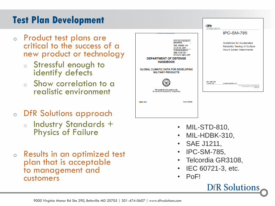
o Identify and document two key metrics
o Desired lifetime
o Defined as time the customer is satisfied with
o Should be actively used in development of part and product qualification
o Product performance
o Returns during the warranty period
o Survivability over lifetime at a set confidence level
o MTBF or MTTF (try to avoid unless required by customer)
9
© 2004 - 2007 © 2004 - 2010 9000 Virginia Manor Rd Ste 290, Beltsville MD 20705 | 301-474-0607 | www.dfrsolutions.com
Test Plan Development – Define Use Environment
o The critical first step is a good understanding of the shipping
and use environment for the product.
o Do you really understand the customer and how they use your
product (even the corner cases)?
o How well is the product protected during shipping (truck, ship,
plane, parachute, storage, etc.)?
o Do you have data or are you guessing?
o Temp/humidity, thermal cycling, ambient temp/operating temp.
o Salt, sulfur, dust, fluids, etc.
o Mechanical cycles (lid cycling, connector cycling, torsion, etc.)
10
© 2004 - 2007 © 2004 - 2010 9000 Virginia Manor Rd Ste 290, Beltsville MD 20705 | 301-474-0607 | www.dfrsolutions.com
Identify Use Environment
o Old School Approach: Use of industry/military specifications
o Military, IPC, Telcordia, ASTM…..
o Advantages
o No additional cost!
o Sometimes very comprehensive
o Agreement throughout the industry
o Missing information? Consider standards from other industries
o Disadvantages
o Most more than 20 years old
o Always less or greater than actual (by how much, unknown)
IPC SM785
MIL HDBK310
© 2004 - 2007 © 2004 - 2010 9000 Virginia Manor Rd Ste 290, Beltsville MD 20705 | 301-474-0607 | www.dfrsolutions.com
Use Environment (cont.)
o Better Approach: Based on actual measurements of similar products in similar environments
o Determine average and realistic worst-case
o Identify all failure-inducing loads
o Include all environments
o Manufacturing
o Transportation
o Storage
o Field
© 2004 - 2007 © 2004 - 2010 9000 Virginia Manor Rd Ste 290, Beltsville MD 20705 | 301-474-0607 | www.dfrsolutions.com
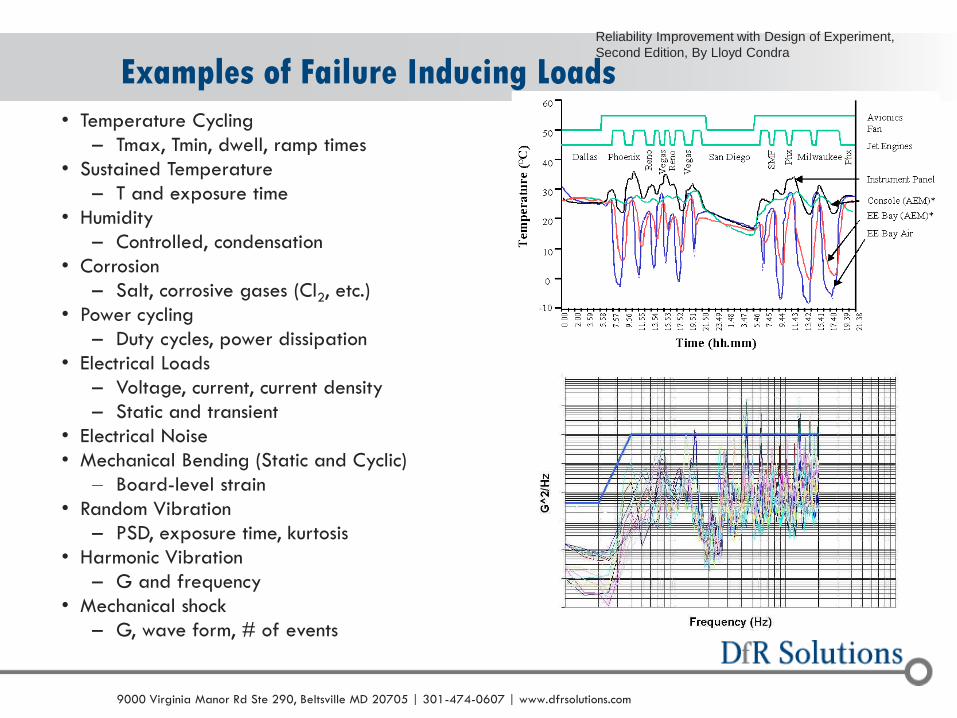
Examples of Failure Inducing Loads
• Temperature Cycling
– Tmax, Tmin, dwell, ramp times
• Sustained Temperature
– T and exposure time
• Humidity
– Controlled, condensation
• Corrosion
– Salt, corrosive gases (Cl2, etc.)
• Power cycling
– Duty cycles, power dissipation
• Electrical Loads
– Voltage, current, current density
– Static and transient
• Electrical Noise
• Mechanical Bending (Static and Cyclic)
– Board-level strain
• Random Vibration
– PSD, exposure time, kurtosis
• Harmonic Vibration
– G and frequency
• Mechanical shock
– G, wave form, # of events
Reliability Improvement with Design of Experiment,
Second Edition, By Lloyd Condra

© 2004 - 2007 © 2004 - 2010 9000 Virginia Manor Rd Ste 290, Beltsville MD 20705 | 301-474-0607 | www.dfrsolutions.com
Use Environment: Best Practice
o Use standards when…
o Certain aspects of your environment are common
o No access to real use environment
o Measure when…
o Certain aspects of your environment are unique
o Strong relationship with customer
o Do not mistake test specifications for the actual use
environment
o Common mistake
© 2004 - 2007 © 2004 - 2010 9000 Virginia Manor Rd Ste 290, Beltsville MD 20705 | 301-474-0607 | www.dfrsolutions.com
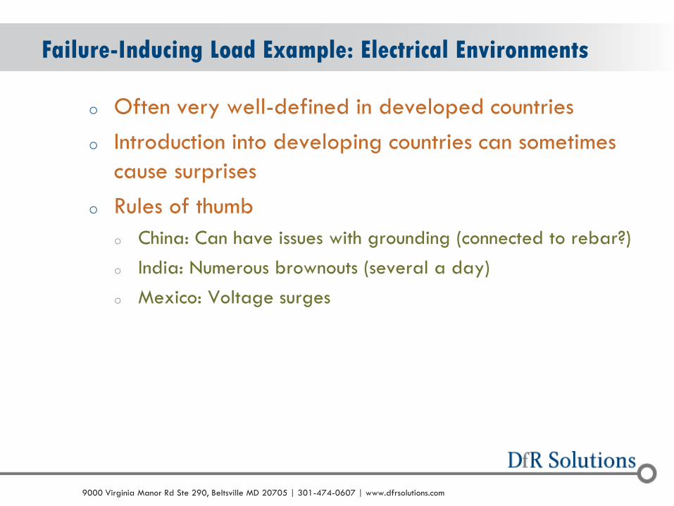
Failure-Inducing Load Example: Electrical Environments
o Often very well-defined in developed countries
o Introduction into developing countries can sometimes
cause surprises
o Rules of thumb
o China: Can have issues with grounding (connected to rebar?)
o India: Numerous brownouts (several a day)
o Mexico: Voltage surges
© 2004 - 2007 © 2004 - 2010 9000 Virginia Manor Rd Ste 290, Beltsville MD 20705 | 301-474-0607 | www.dfrsolutions.com
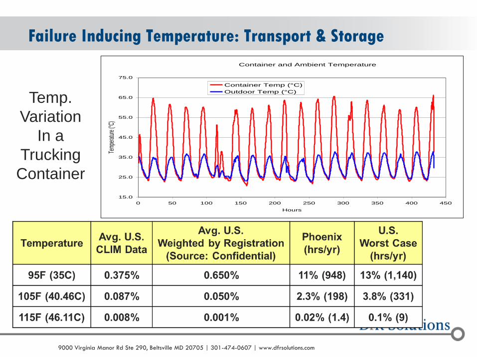
Failure Inducing Temperature: Transport & Storage
Container and Ambient Temperature
15.0
25.0
35.0
45.0
55.0
65.0
75.0
0 50 100 150 200 250 300 350 400 450
Hours
Tem
pera
ture
(°C)
Container Temp (°C)
Outdoor Temp (°C)
Temp.
Variation
In a
Trucking
Container

© 2004 - 2007 © 2004 - 2010 9000 Virginia Manor Rd Ste 290, Beltsville MD 20705 | 301-474-0607 | www.dfrsolutions.com
Temperature: Long-Term Exposure
o For electronics used outside with minimal power dissipation, the diurnal
(daily) temperature cycle provides the primary degradation-inducing
load
Month Cycles/Year Ramp Dwell Max. Temp (oC) Min. Temp. (
oC)
Jan.+Feb.+Dec. 90 6 hrs 6 hrs 20 5
March+November 60 6 hrs 6 hrs 25 10
April+October 60 6 hrs 6 hrs 30 15
May+September 60 6 hrs 6 hrs 35 20
June+July+August 90 6 hrs 6 hrs 40 25
Phoenix, AZ
© 2004 - 2007 © 2004 - 2010 9000 Virginia Manor Rd Ste 290, Beltsville MD 20705 | 301-474-0607 | www.dfrsolutions.com
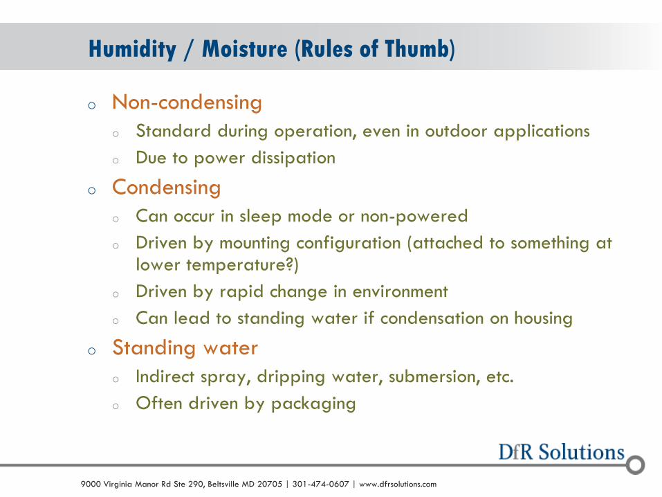
Humidity / Moisture (Rules of Thumb)
o Non-condensing
o Standard during operation, even in outdoor applications
o Due to power dissipation
o Condensing
o Can occur in sleep mode or non-powered
o Driven by mounting configuration (attached to something at lower temperature?)
o Driven by rapid change in environment
o Can lead to standing water if condensation on housing
o Standing water
o Indirect spray, dripping water, submersion, etc.
o Often driven by packaging
© 2004 - 2007 © 2004 - 2010 9000 Virginia Manor Rd Ste 290, Beltsville MD 20705 | 301-474-0607 | www.dfrsolutions.com
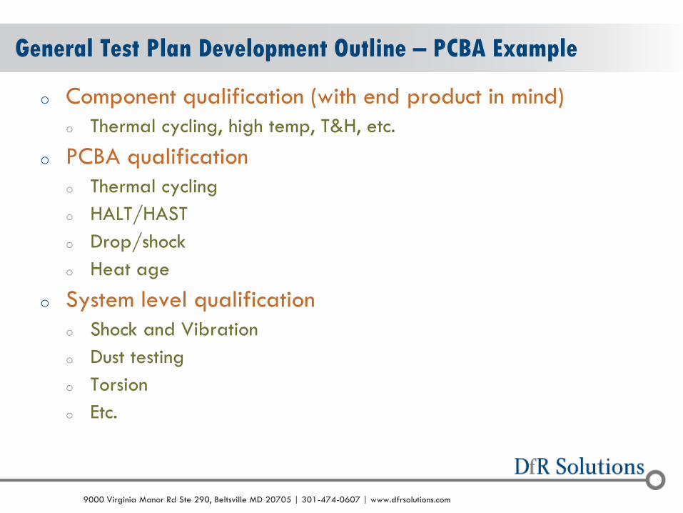
General Test Plan Development Outline – PCBA Example
o Component qualification (with end product in mind)
o Thermal cycling, high temp, T&H, etc.
o PCBA qualification
o Thermal cycling
o HALT/HAST
o Drop/shock
o Heat age
o System level qualification
o Shock and Vibration
o Dust testing
o Torsion
o Etc.
19

© 2004 - 2007 © 2004 - 2010 9000 Virginia Manor Rd Ste 290, Beltsville MD 20705 | 301-474-0607 | www.dfrsolutions.com
Test Plan Development – for PCBAs continued…
o Develop a comprehensive test plan
o Assemble boards at optimum conditions
o Rework specified components on some boards
o Visually inspect and electrically test
o C-SAM & X-ray inspect critical components on 5 or more boards (+3 reworked for BGAs)
o Use these boards for further reliability testing (TC, HALT, S&V)
o Perform failure analysis
o Compile results and review
© 2004 - 2007 © 2004 - 2010 9000 Virginia Manor Rd Ste 290, Beltsville MD 20705 | 301-474-0607 | www.dfrsolutions.com
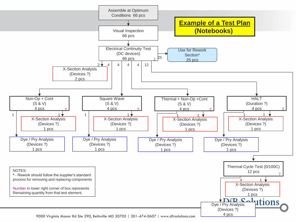
21
Assemble at Optimum
Conditions 66 pcs
Visual Inspection
66 pcs
Electrical Continuity Test
(DC devices)
66 pcs
Send to Intel
10 pcs
X-Section Analysis
(Devices ?)
2 pcs
Thermal Cycle Test (0/100C)
12 pcs
X-Section Analysis
(Devices ?)
1 pcs
Non-Op + Cont
(S & V)
4 pcs
X-Section Analysis
(Devices ?)
1 pcs
Square Wave
(S & V)
4 pcs
X-Section Analysis
(Devices ?)
1 pcs
2 4 4
1 1
4
HALT
(Duration ?)
4 pcs
X-Section Analysis
(Devices ?)
1 pcs
4
1
1
Dye / Pry Analysis
(Devices ?)
1 pcs
1 1
4
1
Dye / Pry Analysis
(Devices ?)
1 pcs
Dye / Pry Analysis
(Devices ?)
4 pcs
Dye / Pry Analysis
(Devices ?)
1 pcs
Thermal + Non-Op +Cont
(S & V)
4 pcs
X-Section Analysis
(Devices ?)
1 pcs
1
Dye / Pry Analysis
(Devices ?)
1 pcs
1
12
10
Example of a Test Plan
(Notebooks)
Use for Rework
Section*
25 pcs 25
1
2 2
7
2 2
NOTES:
* - Rework should follow the supplier’s standard
process for removing and replacing components
Number in lower right corner of box represents
Remaining quantity from that test element.

© 2004 - 2007 © 2004 - 2010 9000 Virginia Manor Rd Ste 290, Beltsville MD 20705 | 301-474-0607 | www.dfrsolutions.com
o Effective failure analysis is critical to reliability!
o Without identifying the root causes of failure, true
corrective action cannot be implemented
o Risk of repeat occurrence increases
o Use a systematic approach to failure analysis
o Proceed from non-destructive to destructive methods until all
root causes are identified.
o Techniques based upon the failure information specific
to the problem.
o Failure history, failure mode, failure site, failure mechanism
Don’t Overlook Failure Analysis!

© 2004 - 2007 © 2004 - 2010 9000 Virginia Manor Rd Ste 290, Beltsville MD 20705 | 301-474-0607 | www.dfrsolutions.com
Virtual Qualification (VQ, Modeling)
o This assessment uses physics-of-failure-based degradation models to predict time-to-failure
o Models include
o Interconnect fatigue (solder joint and plated-through hole)
o Capacitor failure (electrolytic and ceramic)
o Integrated circuit wearout
o Customers develop a degree of assurance that their product will survive for the desired lifetime in the expected use environment

© 2004 - 2007 © 2004 - 2010 9000 Virginia Manor Rd Ste 290, Beltsville MD 20705 | 301-474-0607 | www.dfrsolutions.com
Sherlock ADA – A
Reliability Assurance CAE Tool Suite
- the Physics of Failure App.
It is not at the
Iphone or Droid
App store.
But yes there
is now a
Physics of
Failure
Durability
Simulation App
24
© 2004 - 2007 © 2004 - 2010 9000 Virginia Manor Rd Ste 290, Beltsville MD 20705 | 301-474-0607 | www.dfrsolutions.com
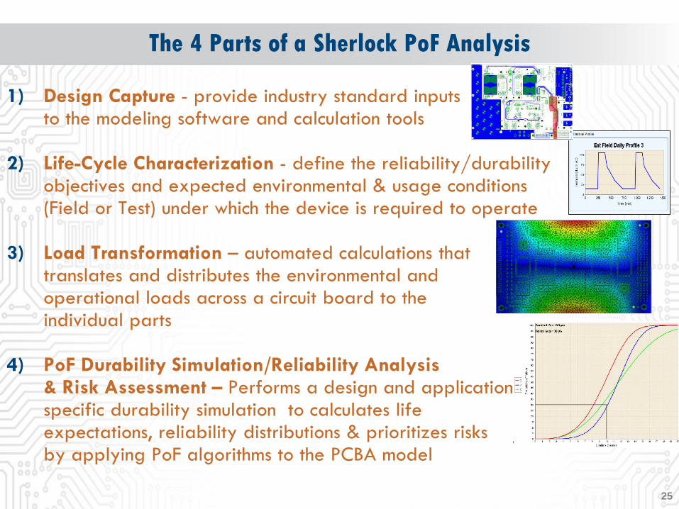
The 4 Parts of a Sherlock PoF Analysis
1) Design Capture - provide industry standard inputs to the modeling software and calculation tools
2) Life-Cycle Characterization - define the reliability/durability objectives and expected environmental & usage conditions (Field or Test) under which the device is required to operate
3) Load Transformation – automated calculations that translates and distributes the environmental and operational loads across a circuit board to the individual parts
4) PoF Durability Simulation/Reliability Analysis & Risk Assessment – Performs a design and application specific durability simulation to calculates life expectations, reliability distributions & prioritizes risks by applying PoF algorithms to the PCBA model
25
© 2004 - 2007 © 2004 - 2010 9000 Virginia Manor Rd Ste 290, Beltsville MD 20705 | 301-474-0607 | www.dfrsolutions.com
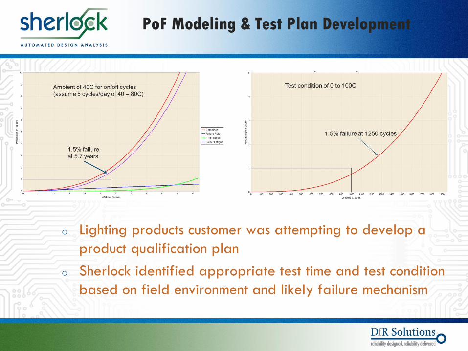
o Lighting products customer was attempting to develop a
product qualification plan
o Sherlock identified appropriate test time and test condition
based on field environment and likely failure mechanism
PoF Modeling & Test Plan Development
© 2004 - 2007 © 2004 - 2010 9000 Virginia Manor Rd Ste 290, Beltsville MD 20705 | 301-474-0607 | www.dfrsolutions.com
When to Repeat Testing: Change Control
o Inadequate change control is responsible for many (some would say most) field failures.
o Examples would include
o Burning Li notebook batteries
o Electrolytic capacitor leakage
o Recent flip chip underfill problems
o Coin cell battery contact failure
o Heat sink clogging failure
o DDR2 Memory modules
o ImAg corrosion
o All changes need to be evaluated carefully (testing to failure recommended).
27

© 2004 - 2007 © 2004 - 2010 9000 Virginia Manor Rd Ste 290, Beltsville MD 20705 | 301-474-0607 | www.dfrsolutions.com
On-Going Reliability Testing
o Qualification shows that a limited number of early
manufactured products (maybe even from a pilot line)
are reliable.
o It’s often not possible to create every permutation of
component suppliers in the qual builds.
o How do you know the product will remain reliable as
you go to high volume and new component suppliers
are introduced?
o There is no perfect answer but an ORT program can
help.
28
© 2004 - 2007 © 2004 - 2010 9000 Virginia Manor Rd Ste 290, Beltsville MD 20705 | 301-474-0607 | www.dfrsolutions.com
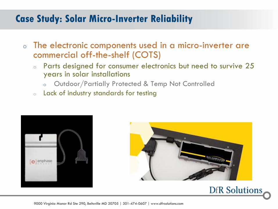
Case Study: Solar Micro-Inverter Reliability
o The electronic components used in a micro-inverter are commercial off-the-shelf (COTS) o Parts designed for consumer electronics but need to survive 25
years in solar installations
o Outdoor/Partially Protected & Temp Not Controlled
o Lack of industry standards for testing
© 2004 - 2007 © 2004 - 2010 9000 Virginia Manor Rd Ste 290, Beltsville MD 20705 | 301-474-0607 | www.dfrsolutions.com
What can be done?
o How can a micro-inverter supplier design the product to meet
the requirements AND convince the customer of this?
o One new method: model the reliability of an electronic
assembly in a variety of conditions based on the design
(before building anything).
o Design for Reliability (DfR) concepts and Physics of Failure
(PoF) are used.
© 2004 - 2007 © 2004 - 2010 9000 Virginia Manor Rd Ste 290, Beltsville MD 20705 | 301-474-0607 | www.dfrsolutions.com
Are there Methods to Model these Failure Mechanisms?
o Yes!
o Algorithms exist to estimate the failure rate from solder joint fatigue for different types of components.
o IPC TR-579 models PTH reliability
o Risk for CAF can be determined
o Finite Element Analysis can be used for Shock & Vibration risk.
o MTBF calculations can be performed to estimate component failure rates.
© 2004 - 2007 © 2004 - 2010 9000 Virginia Manor Rd Ste 290, Beltsville MD 20705 | 301-474-0607 | www.dfrsolutions.com
Micro-Inverter Environment
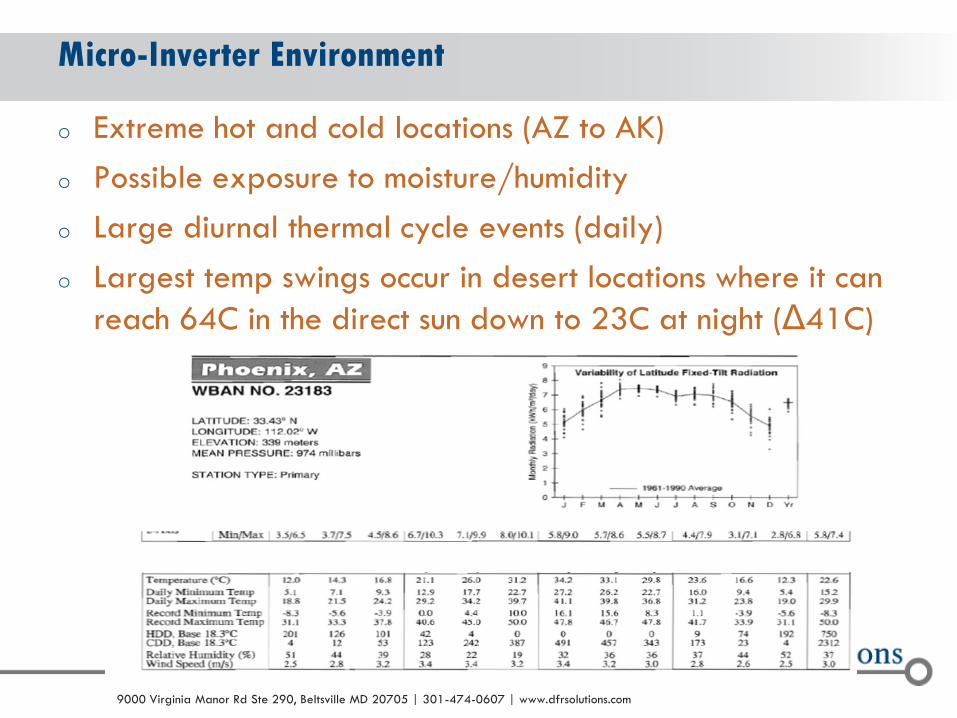
o Extreme hot and cold locations (AZ to AK)
o Possible exposure to moisture/humidity
o Large diurnal thermal cycle events (daily)
o Largest temp swings occur in desert locations where it can
reach 64C in the direct sun down to 23C at night (Δ41C)

© 2004 - 2007 © 2004 - 2010 9000 Virginia Manor Rd Ste 290, Beltsville MD 20705 | 301-474-0607 | www.dfrsolutions.com
Potential Inverter Failure Mechanisms
o Solder joint fatigue failure
o Plated through hole fatigue
failure
o Conductive anodic filament
formation (CAF)
o Shock or Vibration (during
shipping)
o Component wear out
© 2004 - 2007 © 2004 - 2010 9000 Virginia Manor Rd Ste 290, Beltsville MD 20705 | 301-474-0607 | www.dfrsolutions.com
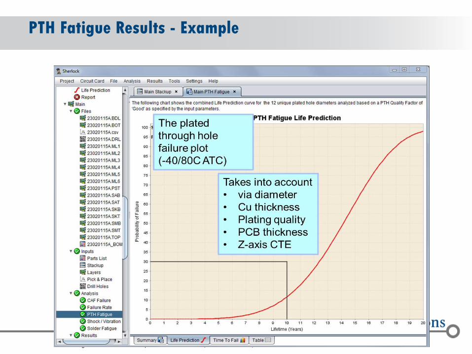
PTH Fatigue Results - Example

© 2004 - 2007 © 2004 - 2010 9000 Virginia Manor Rd Ste 290, Beltsville MD 20705 | 301-474-0607 | www.dfrsolutions.com
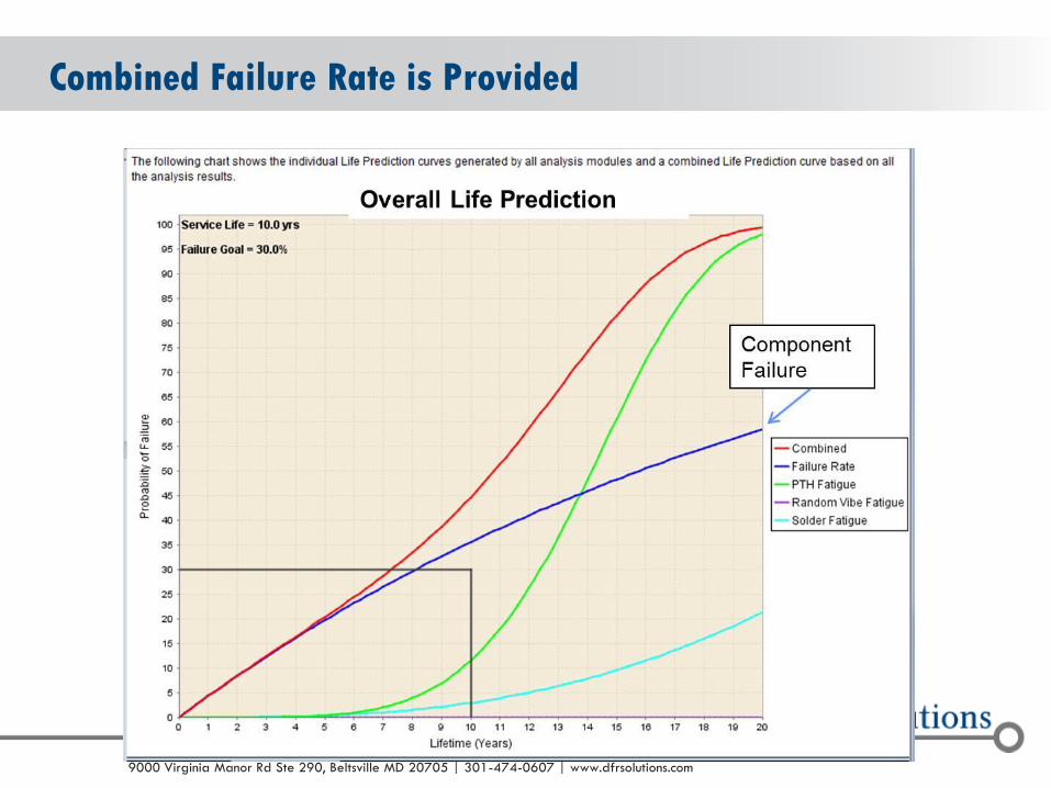
Combined (SJ & PTH) Lifetime Prediction
o Combines analysis results into overall failure prediction curve
PTH
Solder Joint
Combined
© 2004 - 2007 © 2004 - 2010 9000 Virginia Manor Rd Ste 290, Beltsville MD 20705 | 301-474-0607 | www.dfrsolutions.com
Combined Failure Rate is Provided
© 2004 - 2007 © 2004 - 2010 9000 Virginia Manor Rd Ste 290, Beltsville MD 20705 | 301-474-0607 | www.dfrsolutions.com
Additional Uses for Modeling
o Use Sherlock to determine thermal cycle test
requirements.
o Use to modify mount point locations
o Use to determine ESS conditions
o Component Replacement
o Determine impact of changing to Pb-free solder
o Determine expected warranty costs
© 2004 - 2007 © 2004 - 2010 9000 Virginia Manor Rd Ste 290, Beltsville MD 20705 | 301-474-0607 | www.dfrsolutions.com
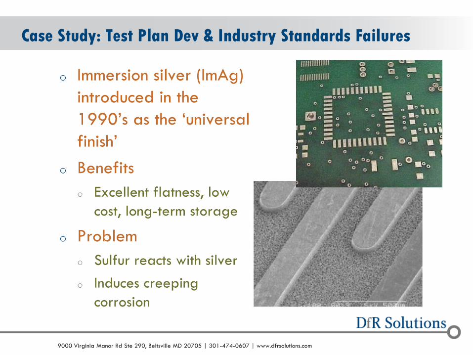
Case Study: Test Plan Dev & Industry Standards Failures
o Immersion silver (ImAg)
introduced in the
1990’s as the ‘universal
finish’
o Benefits
o Excellent flatness, low
cost, long-term storage
o Problem
o Sulfur reacts with silver
o Induces creeping
corrosion
© 2004 - 2007 © 2004 - 2010 9000 Virginia Manor Rd Ste 290, Beltsville MD 20705 | 301-474-0607 | www.dfrsolutions.com
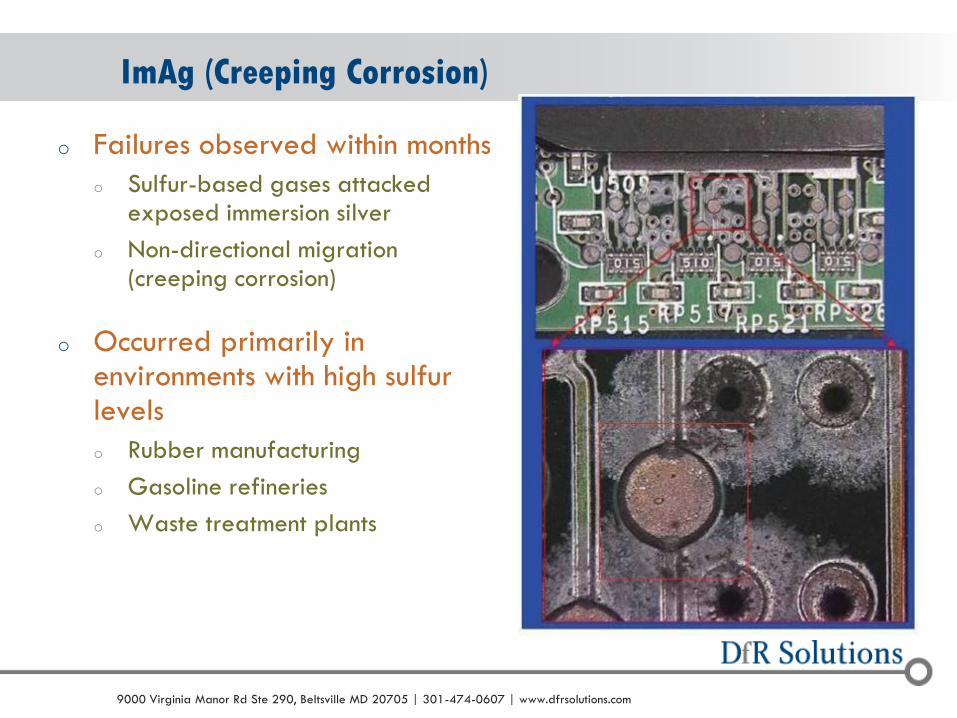
ImAg (Creeping Corrosion)
o Failures observed within months
o Sulfur-based gases attacked exposed immersion silver
o Non-directional migration (creeping corrosion)
o Occurred primarily in environments with high sulfur levels
o Rubber manufacturing
o Gasoline refineries
o Waste treatment plants
© 2004 - 2007 © 2004 - 2010 9000 Virginia Manor Rd Ste 290, Beltsville MD 20705 | 301-474-0607 | www.dfrsolutions.com
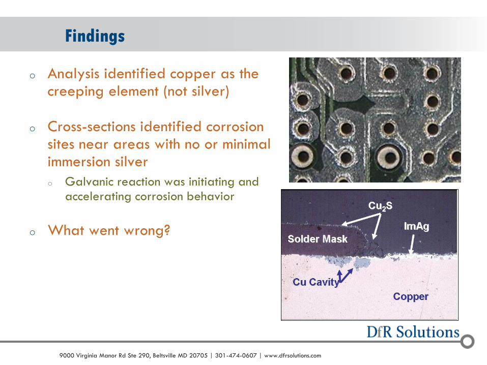
Findings
o Analysis identified copper as the creeping element (not silver)
o Cross-sections identified corrosion sites near areas with no or minimal immersion silver
o Galvanic reaction was initiating and accelerating corrosion behavior
o What went wrong?
© 2004 - 2007 © 2004 - 2010 9000 Virginia Manor Rd Ste 290, Beltsville MD 20705 | 301-474-0607 | www.dfrsolutions.com
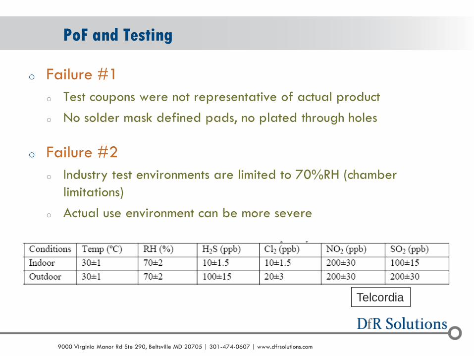
PoF and Testing
o Failure #1
o Test coupons were not representative of actual product
o No solder mask defined pads, no plated through holes
o Failure #2
o Industry test environments are limited to 70%RH (chamber
limitations)
o Actual use environment can be more severe
Telcordia
© 2004 - 2007 © 2004 - 2010 9000 Virginia Manor Rd Ste 290, Beltsville MD 20705 | 301-474-0607 | www.dfrsolutions.com
PoF and Immersion Silver
o The Final Failure?
o Acknowledging the reactivity of silver with sulfur and
moving beyond ‘test to spec’ to truly capture potential
risks
o The ‘physics’ was not well enough understood before the new
material was released
© 2004 - 2007 © 2004 - 2010 9000 Virginia Manor Rd Ste 290, Beltsville MD 20705 | 301-474-0607 | www.dfrsolutions.com 43
Summary
o Product test plans are critical to the success of a new product or technology
o Stressful enough to identify defects
o Show correlation to a realistic environment
o PoF Knowledge can be used to develop test plans and profiles that can be correlated to the field.
o Change control processes and testing should not be overlooked (reliability engineer needs to stay involved in sustaining).
o On-going reliability testing can be a useful (but admittedly imperfect) tool.
o PoF Modeling is an excellent tool to help tailor & optimize physical testing plans

© 2004 - 2007 © 2004 - 2010 9000 Virginia Manor Rd Ste 290, Beltsville MD 20705 | 301-474-0607 | www.dfrsolutions.com
THANKS!! Greg Caswell
Sr. Member of the Technical Staff
DfR Solutions
301-640-5825