Embed Size (px)
Citation preview
Contents lists available at ScienceDirect
Journal of Sound and Vibration
Journal of Sound and Vibration 330 (2011) 5812–5819
0022-46
doi:10.1
� Cor
E-m
journal homepage: www.elsevier.com/locate/jsvi
Effective mass overshoot in single degree of freedom mechanicalsystems with a particle damper
Martın Sanchez a,b, Luis A. Pugnaloni a,�
a Instituto de Fısica de Lıquidos y Sistemas Biologicos (CONICET La Plata, UNLP), Calle 59 Nro 789, 1900 La Plata, Argentinab Departamento de Ingenierıa Mecanica, Facultad Regional La Plata, Universidad Tecnologica Nacional, 60 esq. 124 S/N, 1900 La Plata, Argentina
a r t i c l e i n f o
Article history:
Received 25 April 2011
Received in revised form
12 July 2011
Accepted 15 July 2011
Handling Editor: H. Ouyangsimulation studies, we show that, for small containers, the system does not approach the
Available online 12 August 2011
0X/$ - see front matter & 2011 Elsevier Ltd.
016/j.jsv.2011.07.016
responding author. Tel.: þ54 221 423 3283;
ail address: [email protected] (L.A. Pugn
a b s t r a c t
We study the response of a single degree of freedom mechanical system composed of a
primary mass, M, a linear spring, a viscous damper and a particle damper. The particle
damper consists in a prismatic enclosure of variable height that contains spherical grains
(total mass mp). Contrary to what it has been discussed in previous experimental and
fully detuned mass limit in a monotonous way. Rather, the system increases its effective
mass up and above Mþmp before reaching this expected limiting value (which is associated
with the immobilization of the particles due to a very restrictive container). Moreover, we
show that a similar effect appears in the tall container limit where the system reaches
effective masses below the expected asymptotic value M. We present a discussion on the
origin of these overshoot responses and the consequences for industrial applications.
& 2011 Elsevier Ltd. All rights reserved.
1. Introduction
Most mechanical systems, such as rotating machinery and aeronautic or aerospace structures, achieve dampingthrough viscoelastic materials or viscous fluids. In general, viscoelastic materials and viscous fluids are very effective atmoderate temperatures (less than 250 1C), but the performance of these is poor at low and high temperatures. Moreover,these materials degrade over time and lose their effectiveness.
In recent years, particle dampers (PD) have been studied extensively for use in harsh environments where other typesof damping are not efficient. A PD is an element that increases the structural damping by inserting dissipative particles in abox attached to the primary system or by embedding grains within holes in a vibrating structure [1]. The grains absorb thekinetic energy of the primary system and convert it into heat through inelastic collisions and friction between the particlesand between the particles and the walls of the box or hole. This results in a highly nonlinear mechanical system. PD areeffective over a wide frequency range [1]. Moreover, PD are durable, inexpensive, easy to maintain and have great potentialfor vibration and noise suppression for many applications (see e.g. [2,3]).
Parameters such as the size and shape of the particles, density, coefficient of restitution, size and shape of the enclosure,and the type of excitation of the primary system, among many other features, are important in damping performance [4].Thus, appropriate treatment of the PD in a given structure requires careful analysis and design.
PD use a large number of small grains; therefore, its behavior is directly related to cooperative movements of those insidethe cavity. The theoretical models derived from single particle systems [5] are not applicable to predict the performance of
All rights reserved.
fax: þ54 221 425 7317.
aloni).
M. Sanchez, L.A. Pugnaloni / Journal of Sound and Vibration 330 (2011) 5812–5819 5813
multi-particle systems. For more than 15 years, particle dynamics simulations have been used as a powerful tool forinvestigating the behavior of these types of granular systems [6–9].
In previous works, particle dampers composed of containers of various sizes have been considered. In all of these works,the resonant frequency of the Single-Degree-of-Freedom (SDoF) system falls with respect to the undamped system. This isgenerally attributed to the addition of the mass of the particles, mp. At very low excitation amplitudes, the system behavesas if the entire mass of the particles was attached to the primary mass, M, of the container (i.e. Mþmp). If the excitationlevel is increased, the resonant frequency gradually increases (and the damping performance increases). Eventually, theresonant frequency tends to the resonant frequency of the undamped system. This overall behavior has been discussed invarious papers [9,10].
Yang [11] has studied, experimentally, particle dampers under different conditions of excitation, different frequenciesand variable gap size. The gap size is the free space left between the granular bed and the enclosure ceiling when thesystem is at rest. He has found that, under some conditions, the system may display effective masses above Mþmp orbelow M. However, a careful analysis of this phenomenon has not been carried out yet.
In this paper, we discuss results, obtained through simulations via a Discrete Elements Method (DEM), on the resonantfrequency shift of SDoF mechanical systems with granular damping. We show that, contrary to what has been discussedpreviously, for small containers, the system does not approach the fully detuned mass limit in a monotonous way. Rather,the system increases its effective mass up and above Mþmp before reaching the expected limiting value. Moreover, thereis a similar effect in the tall enclosure limit, where the system reaches effective masses below the expected asymptoticvalue M.
2. Discrete elements method
In order to simulate the motion of the particles in the enclosure of a PD we use a DEM. This scheme, first used byCundall and Strack [12], is widely used for numerical simulations of granular media [13]. We implement a velocityVerlet algorithm [14] to update the positions (orientations) and velocities of the particles. Orientations are representedthrough quaternions to prevent numerical singularities [15].
We consider spherical soft particles. If Ri and Rj are the radii of two colliding particles, a¼ RiþRj�dij is the normaldisplacement or virtual overlap between the spheres, where dij is the distance between the centers of the two spheres. Underthese conditions, the interaction force Fn in the normal direction is based on the Hertz–Kuwabara–Kono model [16,17]:
Fn ¼�kna3=2�gnun
ffiffiffiap
, (1)
where kn ¼23 Eð
ffiffiffiffiffiffiffiffiffiR=2
pÞð1�u2Þ
�1 is the normal stiffness (with E the Young’s modulus, u the Poisson’s ratio and R�1 ¼ R�1i þR�1
j ),gn the normal damping coefficient of the viscoelastic contact, and un the relative normal velocity.
On the other hand, the tangential force Fs is based on Coulomb’s law of friction [16,18]. We used a simplified model inwhich the friction force takes the minimum value between the shear damping force and the dynamic friction:
Fs ¼�min ð9gsus
ffiffiffiap
9,9mdFn9ÞsgnðusÞ, (2)
where gs is the shear damping coefficient, us the relative tangential velocity between the two spheres in contact and md thedynamic friction coefficient. The sign function indicates that the friction force always opposes the direction of the relativetangential velocity.
The particles are enclosed in a prismatic container (the box or enclosure) built up of six flat walls with the samematerial properties as the particles defined through the parameters in Eqs. (1) and (2).
3. The SDoF model
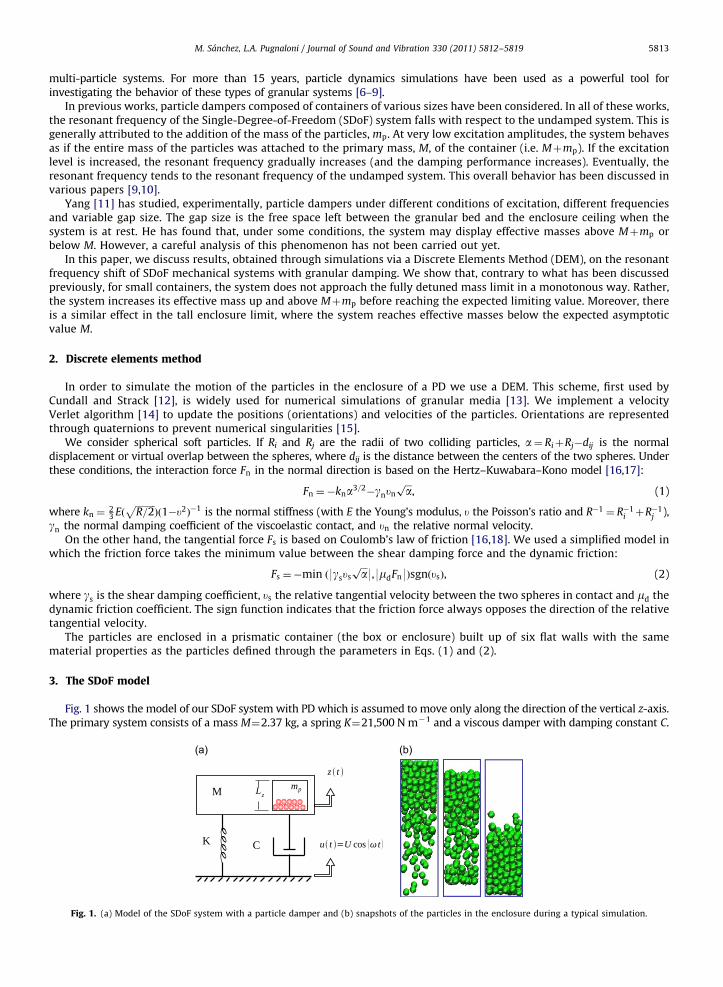
Fig. 1 shows the model of our SDoF system with PD which is assumed to move only along the direction of the vertical z-axis.The primary system consists of a mass M¼2.37 kg, a spring K¼21,500 N m�1 and a viscous damper with damping constant C.
Fig. 1. (a) Model of the SDoF system with a particle damper and (b) snapshots of the particles in the enclosure during a typical simulation.
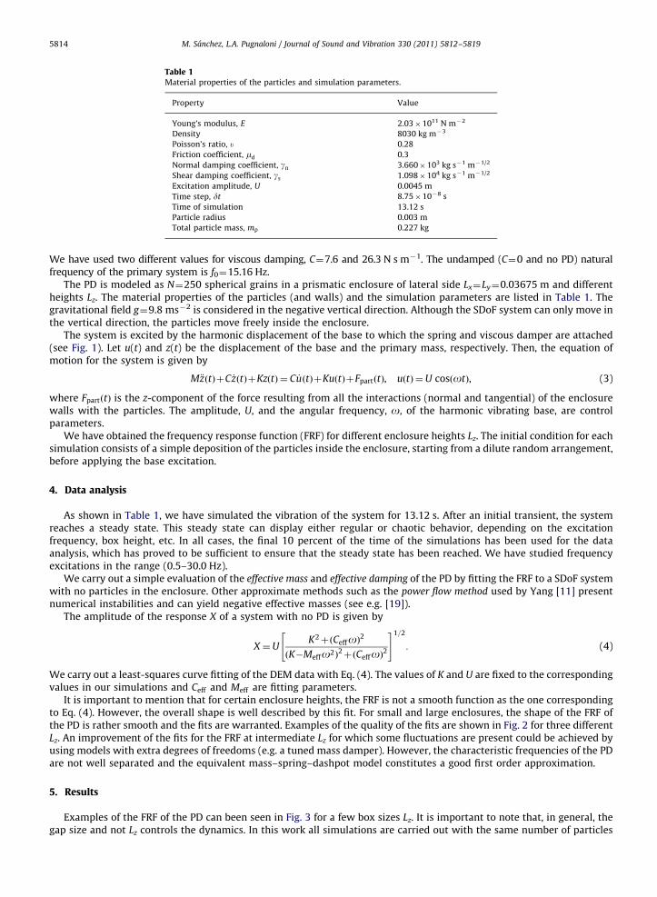
Table 1Material properties of the particles and simulation parameters.
Property Value
Young’s modulus, E 2.03�1011 N m�2
Density 8030 kg m�3
Poisson’s ratio, u 0.28
Friction coefficient, md 0.3
Normal damping coefficient, gn 3.660�103 kg s�1 m�1/2
Shear damping coefficient, gs 1.098�104 kg s�1 m�1/2
Excitation amplitude, U 0.0045 m
Time step, dt 8.75�10�8 s
Time of simulation 13.12 s
Particle radius 0.003 m
Total particle mass, mp 0.227 kg
M. Sanchez, L.A. Pugnaloni / Journal of Sound and Vibration 330 (2011) 5812–58195814
We have used two different values for viscous damping, C¼7.6 and 26.3 N s m�1. The undamped (C¼0 and no PD) naturalfrequency of the primary system is f0¼15.16 Hz.
The PD is modeled as N¼250 spherical grains in a prismatic enclosure of lateral side Lx¼Ly¼0.03675 m and differentheights Lz. The material properties of the particles (and walls) and the simulation parameters are listed in Table 1. Thegravitational field g¼9.8 ms�2 is considered in the negative vertical direction. Although the SDoF system can only move inthe vertical direction, the particles move freely inside the enclosure.
The system is excited by the harmonic displacement of the base to which the spring and viscous damper are attached(see Fig. 1). Let u(t) and z(t) be the displacement of the base and the primary mass, respectively. Then, the equation ofmotion for the system is given by
M €zðtÞþC _zðtÞþKzðtÞ ¼ C _uðtÞþKuðtÞþFpartðtÞ, uðtÞ ¼U cosðotÞ, (3)
where FpartðtÞ is the z-component of the force resulting from all the interactions (normal and tangential) of the enclosurewalls with the particles. The amplitude, U, and the angular frequency, o, of the harmonic vibrating base, are controlparameters.
We have obtained the frequency response function (FRF) for different enclosure heights Lz. The initial condition for eachsimulation consists of a simple deposition of the particles inside the enclosure, starting from a dilute random arrangement,before applying the base excitation.
4. Data analysis
As shown in Table 1, we have simulated the vibration of the system for 13.12 s. After an initial transient, the systemreaches a steady state. This steady state can display either regular or chaotic behavior, depending on the excitationfrequency, box height, etc. In all cases, the final 10 percent of the time of the simulations has been used for the dataanalysis, which has proved to be sufficient to ensure that the steady state has been reached. We have studied frequencyexcitations in the range (0.5–30.0 Hz).
We carry out a simple evaluation of the effective mass and effective damping of the PD by fitting the FRF to a SDoF systemwith no particles in the enclosure. Other approximate methods such as the power flow method used by Yang [11] presentnumerical instabilities and can yield negative effective masses (see e.g. [19]).
The amplitude of the response X of a system with no PD is given by
X ¼UK2þðCeffoÞ2
ðK�Meffo2Þ2þðCeffoÞ2
" #1=2
: (4)
We carry out a least-squares curve fitting of the DEM data with Eq. (4). The values of K and U are fixed to the correspondingvalues in our simulations and Ceff and Meff are fitting parameters.
It is important to mention that for certain enclosure heights, the FRF is not a smooth function as the one correspondingto Eq. (4). However, the overall shape is well described by this fit. For small and large enclosures, the shape of the FRF ofthe PD is rather smooth and the fits are warranted. Examples of the quality of the fits are shown in Fig. 2 for three differentLz. An improvement of the fits for the FRF at intermediate Lz for which some fluctuations are present could be achieved byusing models with extra degrees of freedoms (e.g. a tuned mass damper). However, the characteristic frequencies of the PDare not well separated and the equivalent mass–spring–dashpot model constitutes a good first order approximation.
5. Results
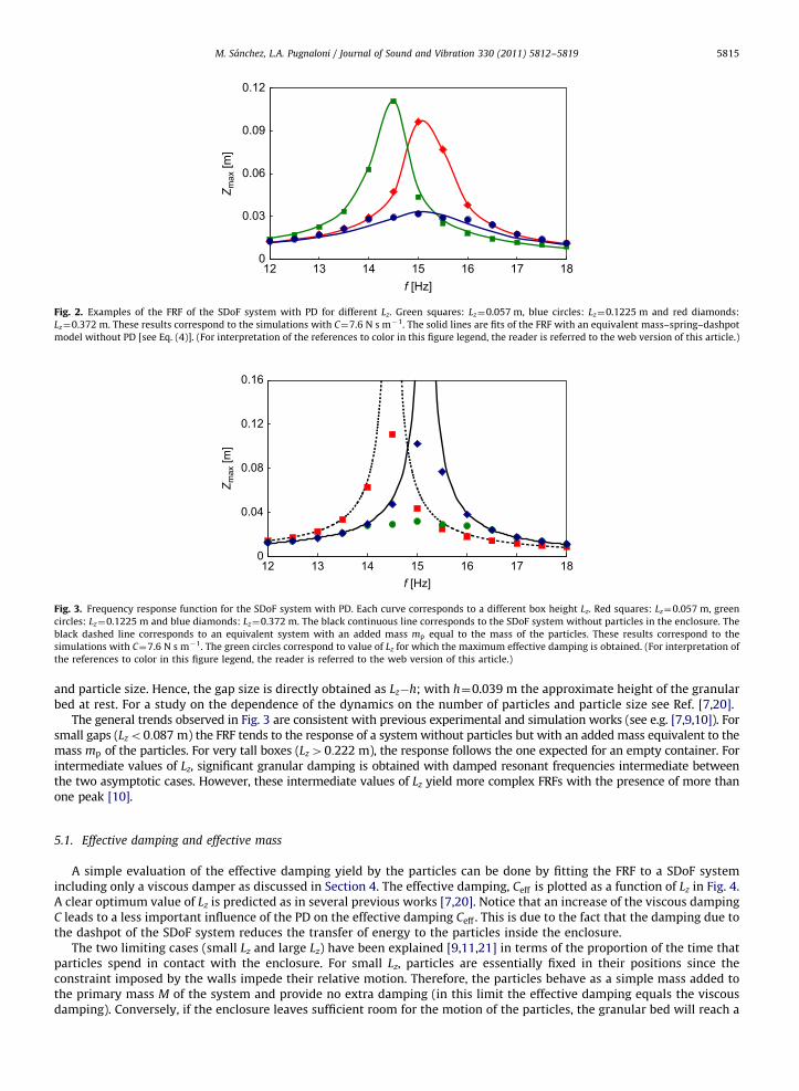
Examples of the FRF of the PD can been seen in Fig. 3 for a few box sizes Lz. It is important to note that, in general, thegap size and not Lz controls the dynamics. In this work all simulations are carried out with the same number of particles
0
0.03
0.06
0.09
0.12
12f [Hz]
Z max
[m]
13 14 15 16 17 18
Fig. 2. Examples of the FRF of the SDoF system with PD for different Lz. Green squares: Lz¼0.057 m, blue circles: Lz¼0.1225 m and red diamonds:
Lz¼0.372 m. These results correspond to the simulations with C¼7.6 N s m�1. The solid lines are fits of the FRF with an equivalent mass–spring–dashpot
model without PD [see Eq. (4)]. (For interpretation of the references to color in this figure legend, the reader is referred to the web version of this article.)
0
0.04
0.08
0.12
0.16
12f [Hz]
Z max
[m]
13 14 15 16 17 18
Fig. 3. Frequency response function for the SDoF system with PD. Each curve corresponds to a different box height Lz. Red squares: Lz¼0.057 m, green
circles: Lz¼0.1225 m and blue diamonds: Lz¼0.372 m. The black continuous line corresponds to the SDoF system without particles in the enclosure. The
black dashed line corresponds to an equivalent system with an added mass mp equal to the mass of the particles. These results correspond to the
simulations with C¼7.6 N s m�1. The green circles correspond to value of Lz for which the maximum effective damping is obtained. (For interpretation of
the references to color in this figure legend, the reader is referred to the web version of this article.)
M. Sanchez, L.A. Pugnaloni / Journal of Sound and Vibration 330 (2011) 5812–5819 5815
and particle size. Hence, the gap size is directly obtained as Lz�h; with h¼0.039 m the approximate height of the granularbed at rest. For a study on the dependence of the dynamics on the number of particles and particle size see Ref. [7,20].
The general trends observed in Fig. 3 are consistent with previous experimental and simulation works (see e.g. [7,9,10]). Forsmall gaps (Lzo0:087 m) the FRF tends to the response of a system without particles but with an added mass equivalent to themass mp of the particles. For very tall boxes (Lz40:222 m), the response follows the one expected for an empty container. Forintermediate values of Lz, significant granular damping is obtained with damped resonant frequencies intermediate betweenthe two asymptotic cases. However, these intermediate values of Lz yield more complex FRFs with the presence of more thanone peak [10].
5.1. Effective damping and effective mass
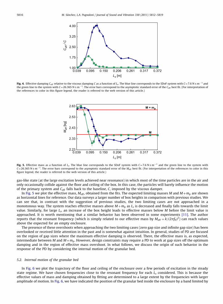
A simple evaluation of the effective damping yield by the particles can be done by fitting the FRF to a SDoF systemincluding only a viscous damper as discussed in Section 4. The effective damping, Ceff is plotted as a function of Lz in Fig. 4.A clear optimum value of Lz is predicted as in several previous works [7,20]. Notice that an increase of the viscous dampingC leads to a less important influence of the PD on the effective damping Ceff . This is due to the fact that the damping due tothe dashpot of the SDoF system reduces the transfer of energy to the particles inside the enclosure.
The two limiting cases (small Lz and large Lz) have been explained [9,11,21] in terms of the proportion of the time thatparticles spend in contact with the enclosure. For small Lz, particles are essentially fixed in their positions since theconstraint imposed by the walls impede their relative motion. Therefore, the particles behave as a simple mass added tothe primary mass M of the system and provide no extra damping (in this limit the effective damping equals the viscousdamping). Conversely, if the enclosure leaves sufficient room for the motion of the particles, the granular bed will reach a
1.00
1.75
2.50
3.25
4.00
0.039Lz [m]
Cef
f / C
0.095 0.150 0.206 0.261 0.317 0.372
Fig. 4. Effective damping Ceff relative to the viscous damping C as a function of Lz. The blue line corresponds to the SDoF system with C¼7.6 N s m�1 and
the green line to the system with C¼26.365 N s m�1. The error bars correspond to the asymptotic standard error of the Ceff best fit. (For interpretation of
the references to color in this figure legend, the reader is referred to the web version of this article.)
2.23
2.33
2.43
2.53
2.63
0.039Lz [m]
Mef
f [kg
]
M + mp
M
0.095 0.150 0.206 0.261 0.317 0.372
Fig. 5. Effective mass as a function of Lz. The blue line corresponds to the SDoF system with C¼7.6 N s m�1 and the green line to the system with
C¼26.365 N s m�1. The error bars correspond to the asymptotic standard error of the Meff best fit. (For interpretation of the references to color in this
figure legend, the reader is referred to the web version of this article.)
M. Sanchez, L.A. Pugnaloni / Journal of Sound and Vibration 330 (2011) 5812–58195816
gas-like state (at the large excitation levels achieved near resonance) in which most of the time particles are in the air andonly occasionally collide against the floor and ceiling of the box. In this case, the particles will barely influence the motionof the primary system and Ceff falls back to the baseline, C, imposed by the viscous damper.
In Fig. 5 we plot the effective mass, Meff , obtained from the fits. The expected limiting masses M and Mþmp are shownas horizontal lines for reference. Our data surveys a larger number of box heights in comparison with previous studies. Wecan see that, in contrast with the suggestion of previous studies, the two limiting cases are not approached in amonotonous way. The system reaches effective masses above Mþmp as Lz is decreased and finally falls towards the limitvalue. Similarly, for large Lz, an increase of the box height leads to effective masses below M before the limit value isapproached. It is worth mentioning that a similar behavior has been observed in some experiments [11]. The authorreports that the resonant frequency (which is simply related to our effective mass by Meff ¼ k=ð2pf0Þ
2) can reach valuesabove the expected for an empty enclosure.
The presence of these overshoots when approaching the two limiting cases (zero gap size and infinite gap size) has beenoverlooked or received little attention in the past and is somewhat against intuition. In general, studies of PD are focusedon the region of gap sizes where the maximum effective damping is observed. There, the effective mass is, as expected,intermediate between M and Mþmp. However, design constraints may require a PD to work at gap sizes off the optimumdamping and in the region of effective mass overshoot. In what follows, we discuss the origin of such behavior in theresponse of the PD by considering the internal motion of the granular bed.
5.2. Internal motion of the granular bed
In Fig. 6 we plot the trajectory of the floor and ceiling of the enclosure over a few periods of excitation in the steadystate regime. We have chosen frequencies close to the resonant frequency for each Lz considered. This is because theeffective values of mass and damping obtained by fitting are determined to a large extent by the frequencies with largeramplitude of motion. In Fig. 6, we have indicated the position of the granular bed inside the enclosure by a band limited by
2.23
2.38
2.53
2.68
0.039Lz [m]
Mef
f [kg
]
M + m p
M
(a)
(b)
(c)
(d)
(e)(f)
(g)
0.122 0.205 0.289 0.372
-0.2
-0.1
0
0.1
0.2
12.95 12.99 13.03 13.08 13.12
z(t)
-100
-60
-20
20
60
100
Fpa
rt/ M
g
-0.2
-0.1
0
0.1
0.2
12.95 12.99 13.03 13.08 13.12
t [s]t [s]
t [s]t [s]
t [s]t [s]
t [s]
z(t)
-100
-60
-20
20
60
100
Fpa
rt / M
g
-0.1
0
0.1
0.2
12.95 12.99 13.03 13.08 13.12
z(t)
-100
-60
-20
20
60
100
Fpa
rt / M
g
-0.05
0
0.05
0.1
0.15
12.95 12.99 13.03 13.08 13.12z(
t)-100
-60
-20
20
60
100
Fpa
rtM
g
Fpa
rtM
g
-0.04
0.01
0.06
0.11
0.16
12.95 12.99 13.03 13.08 13.12
z(t)
-100
-60
-20
20
60
100
-0.05
0.01
0.07
0.13
0.19
12.95 12.99 13.03 13.08 13.12
z(t)
-100
-60
-20
20
60
100
Fpa
rtM
g
-0.15
0
0.15
0.3
0.45
12.95 12.99 13.03 13.08 13.12
z(t)
-100
-60
-20
20
60
100
Fpa
rtM
g
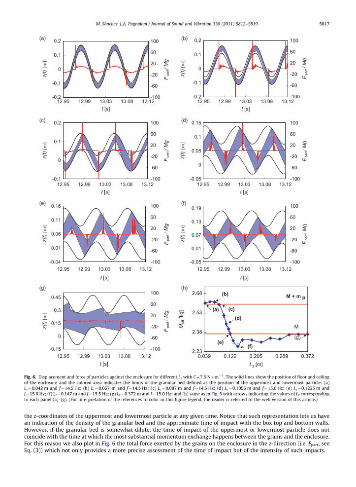
Fig. 6. Displacement and force of particles against the enclosure for different Lz with C¼7.6 N s m�1. The solid lines show the position of floor and ceiling
of the enclosure and the colored area indicates the limits of the granular bed defined as the position of the uppermost and lowermost particle: (a)
Lz¼0.042 m and f¼14.5 Hz; (b) Lz¼0.057 m and f¼14.5 Hz; (c) Lz¼0.087 m and f¼14.5 Hz; (d) Lz¼0.1095 m and f¼15.0 Hz; (e) Lz¼0.1225 m and
f¼15.0 Hz; (f) Lz¼0.147 m and f¼15.5 Hz; (g) Lz¼0.372 m and f¼15.0 Hz; and (h) same as in Fig. 5 with arrows indicating the values of Lz corresponding
to each panel (a)–(g). (For interpretation of the references to color in this figure legend, the reader is referred to the web version of this article.)
M. Sanchez, L.A. Pugnaloni / Journal of Sound and Vibration 330 (2011) 5812–5819 5817
the z-coordinates of the uppermost and lowermost particle at any given time. Notice that such representation lets us havean indication of the density of the granular bed and the approximate time of impact with the box top and bottom walls.However, if the granular bed is somewhat dilute, the time of impact of the uppermost or lowermost particle does notcoincide with the time at which the most substantial momentum exchange happens between the grains and the enclosure.For this reason we also plot in Fig. 6 the total force exerted by the grains on the enclosure in the z-direction (i.e. Fpart, seeEq. (3)) which not only provides a more precise assessment of the time of impact but of the intensity of such impacts.
M. Sanchez, L.A. Pugnaloni / Journal of Sound and Vibration 330 (2011) 5812–58195818
We recall here that the effective mass of an equivalent mass–spring–dashpot model is associated with the response ofthe PD in phase with the spring force, whereas the effective damping will be associated with the response in phase withthe viscous force.
As we mentioned, for very small gaps, the response of the system is similar to the response of an equivalent SDoFsystem where the total mass of the particles is simply added to the primary mass (i.e. Meff ¼Mþmp). This is due to the factthat the particles are not able to move in such reduced enclosures. As we slightly increase Lz, particles behave as a densepack that travels between the floor and ceiling of the enclosure (see Fig. 6(a)). However, within an oscillation, the granularbed is in full contact with the ceiling or the floor during important portions of the time. During such periods, the granularbed can be considered essentially as an added mass mp. Notice that after leaving the ceiling (floor) the grains hit the floor(ceiling) before the primary system has reached its maximum displacement. The particles transfer momentum to theenclosure against the direction of the spring force. As a consequence, the effective inertia of the system during the impactis equivalent to a sudden mass increase. This effective mass increase exceeds the loss due to the short periods in which thegranular bed is detached from the floor (ceiling) (see the zero force segments in Fig. 6(a)). The overall result is an effectivemass Meff above Mþmp.
If we further increase Lz, the period of detachment within an oscillation increases, but the transfer of momentum atimpact also increases leading to an overall increase of Meff (see Fig. 6(b)). Eventually, the transfer of momentum at impactis exactly balanced by the loss of added mass due to the detachment periods. This makes the system render againMeff ¼Mþmp (see Fig. 6(c)). Interestingly, this crossover occurs when the granular bed hits the floor (ceiling) at the pointof maximum displacement.
There exist a range of values of Lz for which MoMeff oMþmp. In such cases the effective damping is rather high. This ismainly due to the fact that the granular bed hits the enclosure out of phase. In particular, the grains hit the base when boththe primary mass is moving upward and the spring force is pulling upward (see Fig. 6(d)). This results in a strong reductionof the maximum displacement of the system and in an effective added mass with respect to M. However, since the periodsof detachment from the enclosure are significantly long, the average added mass due to the impacts is smaller than mp.
If the impacts happens to be always at the time where no spring force is applied to the primary mass, then the transferof momentum will not result in an effective added mass. This happens when the primary mass pass through theequilibrium point of the spring (i.e. zero displacement). Indeed, we find that there exists a particular value of Lz at whichthe granular bed hits the floor (ceiling) at this point and the effective mass obtained by fitting corresponds to M (i.e. noadded mass, see Fig. 6(e)). It is important to realize that this is also the value of Lz at which the maximum effectivedamping is obtained (see Fig. 4 and Ref. [11,22,23]). Therefore, at the optimum Lz where maximum damping is achieved,the effective mass coincides with the primary mass. This means that the addition of particles to create the PD do not affectthe resonant frequency of the system if the optimum Lz is chosen, which implies that under such conditions there is noneed for compensation of the mass of the particles during design.
As expected, an increase of Lz beyond the optimum damping leads the granular bed to hit the enclosure in phase withthe spring force (see Fig. 6(f)). That is, the grains hit the floor when the spring pulls the system downward. The effect in theapparent inertial response is as if the system suffered a sudden mass decrease. Therefore, the effective mass is smaller thanthe primary mass (notice that here the granular bed is only in contact with the enclosure during the impacts).
Much larger gap sizes lead the granular bed to expand significantly. The granular sample enters a gas-like state withonly a few particles colliding with the enclosure in each oscillation. This transfers little momentum to the primary massand the system presents an Meff which is close to M (see Fig. 6(g)).
6. Conclusions
We have studied a PD by means of simulations via a DEM. We have considered the effective mass and effective dampingof the entire SDoF system by fitting the FRF to a simple mass–spring–dashpot system. In particular, we study the effect ofthe height Lz of the enclosure.
We have observed that the effective mass of the system reaches the two limits described in the literature for small andlarge enclosures. However, those limits are not approached in a monotonous way and clear overshoots appear. For smallgap sizes, the system presents effective masses above the direct sum of the primary mass M and the particle mass mp. Forlarge enclosures, the effective masses fall below M.
We have observed that such behavior can be explained by considering both the period of time over which the granularbed is in full contact with the enclosure and the inertial effects due to the grains hitting the floor or ceiling in or out ofphase with the spring force.
Interestingly, we found that the value of Lz at which Meff crosses M coincides with the optimum damping valuedescribed in the literature. Since the optimum Lz should be simple to interpolate from the intersection with the horizontalM level in a plot of Meff vs Lz, we suggest that such estimation can be a more suitable approach than the search for amaximum in a plot of Ceff versus Lz.
The overshoot effects described are present outside the range of maximal damping performance and might beconsidered of secondary interest in industrial applications at first sight. However, design constrains may require a PD towork off the optimum damping and in one of the overshoot regions. In particular, for enclosures somewhat taller than theone corresponding to the optimum damping, one achieves effective masses only slightly below the primary mass.
M. Sanchez, L.A. Pugnaloni / Journal of Sound and Vibration 330 (2011) 5812–5819 5819
This implies that the resonant frequency is almost unaltered upon addition of the particles. Moreover, such values of Lz
achieve a remarkable damping (although not maximal) while still presenting a FRF with a shape very similar to the oneobserved for a simple SDoF mass–spring–dashpot system. This may simplify the prediction of the behavior of the PD undersuch conditions. On the other hand, if the primary system has more degrees of freedom, the off-design resonantfrequencies may fall in either overshoot regime and the side effects should be taken into consideration.
Although we have studied a PD driven in the direction of gravity, similar results are expected if a horizontal setup isconsidered. It has been shown that near the resonant frequency the response of an impact damper does not depend on therelative direction between the motion of the system and the gravity [5]. Since the effective mass is largely determined bythe response near the resonant frequency, the same general trends should be found in horizontally driven PD.
Acknowledgments
LAP acknowledges financial support from CONICET (Argentina).
References
[1] H.V. Panossian, Structural damping enhancement via non-obstructive particle damping technique, Journal of Vibration and Acoustics 114 (1992)101–105, doi:10.1115/1.2930221.
[2] S.S. Simonian, Particle beam damper, Proceedings of the SPIE Conference on Passive Damping, Vol. 2445, Newport Beach, CA, 1995, pp. 149–160.[3] Z. Xu, M.Y. Wang, T. Chenc, Particle damper for vibration and noise reduction, Journal of Sound and Vibration 270 (2004) 1033–1040, doi:10.1016/
S0022-460X(03)00503-0.[4] K.S. Marhadi, V.K. Kinra, Particle impact damping: effect of mass ratio, material, and shape, Journal of Sound and Vibration 283 (2005) 433–448,
doi:10.1016/j.jsv.2004.04.013.[5] M.R. Duncan, C.R. Wassgren, C.M. Krousgrill, The damping performance of a single particle impact damper, Journal of Sound and Vibration 286 (2005)
123–144, doi:10.1016/j.jsv.2004.09.028.[6] K. Mao, M.Y. Wang, Z. Xu, T. Chend, DEM simulation of particle damping, Powder Technology 142 (2–3) (2004) 154–165, doi:10.1016/
j.powtec.2004.04.031.[7] M. Saeki, Impact damping with granular materials in a horizontally vibration system, Journal of Sound and Vibration 251 (1) (2002) 153–161,
doi:10.1006/jsvi.2001.3985.[8] X.M. Bai, L.M. Keer, Q.J. Wang, R.Q. Snurr, Investigation of particle damping mechanism via particle dynamics simulations, Granular Matter 11 (2009)
417–429, doi:10.1007/s10035-009-0150-6.[9] X. Fang, J. Tang, Granular damping in forced vibration: qualitative and quantitative analyses, Journal of Vibration and Acoustics 128 (2006) 489–500,
doi:10.1115/1.2203339.[10] W. Liu, G.R. Tomlinson, J.A. Rongong, The dynamic characterisation of disk geometry particle dampers, Journal of Sound and Vibration 280 (2005)
849–861, doi:10.1016/j.jsv.2003.12.047.[11] M.Y. Yang, Development of Master Design Curves for Particle Impact Dampers, PhD Thesis, The Pennsylvania State University, 2003.[12] P.A. Cundall, O.D.L. Strack, A discrete numerical model for granular assemblies, Geotechnique 29 (1979) 47–65.[13] T. Poschel, T. Schwager, Computational Granular Dynamics: Models and Algorithms, Springer-Verlag, Berlin, Heidelberg, 2005.[14] M.P. Allen, D.J. Tildesley, Computer Simulation of Liquids, Oxford Science Publications, 1989.[15] H. Goldstein, Classical Mechanics, third ed., Addison Wesley, 2002.[16] J. Schafer, S. Dippel, D.E. Wolf, Force schemes in simulations of granular materials, Journal de Physique I 6 (1996) 5–20.[17] H. Kruggel-Emden, E. Simsek, S. Rickelt, S. Wirtz, V. Scherer, Review and extension of normal force models for the discrete element method,
Powder Technology 171 (2007) 157–173, doi:10.1016/j.powtec.2006.10.004.[18] H. Kruggel-Emden, S. Wirtz, V. Scherer, A study on tangential force laws applicable to the discrete element method (DEM) for materials with
viscoelastic or plastic behavior, Chemical Engineering Science 63 (2008) 1523–1541, doi:10.1016/j.ces.2007.11.025.[19] C.X. Wong, A.B. Spencer, J.A. Rongong, Effects of enclosure geometry on particle damping performance, 50th AIAA/ASME/ASCE/AHS/ASC Structures,
Structural Dynamics and Materials Conference, Palm Springs, California, 2009.[20] M. Sanchez, L.A. Pugnaloni, Modelling of a granular damper, Mecanica Computacional XXIX (2010) 1849–1859.[21] S. Brennan, S.S. Simonian, Parametric test results on particle dampers, 48th AIAA/ASME/ASCE/AHS/ASC Structures, Structural Dynamics and Material
Conference, Honolulu, Hawaii, 2007.[22] R.D. Friend, V.K. Kinra, Particle impact damping, Journal of Sound and Vibration 233 (1) (2000) 93–118, doi:10.1006/jsvi.1999.2795.[23] Z. Lu, X. Lu, S.F. Masri, Studies of the performance of particle dampers under dynamic loads, Journal of Sound and Vibration 329 (2010) 5415–5433,
doi:10.1016/j.jsv.2010.06.027.


![Brane In ation and the Overshoot Problem - arXiv · overshoot problem. However, Underwood [26] recently observed that brane in ation may not su er from the overshoot problem, based](https://img.pdfslide.us/doc/110x75/5f3d1811eed438296023dbdd/brane-in-ation-and-the-overshoot-problem-arxiv-overshoot-problem-however-underwood.jpg)


![ACATacat.or.th/download/acat_or_th/journal-4/04 - 04.pdf · APmin APmax Appendix G [1] AP APmax Overpressure Relief Damper Damper 12 Relief Damper Relief Damper (Vent) Fire Damper](https://img.pdfslide.us/doc/110x75/5f7cb481641db55595223717/-04pdf-apmin-apmax-appendix-g-1-ap-apmax-overpressure-relief-damper-damper.jpg)