Embed Size (px)
Citation preview

Effective March 2017Supersedes February 2015Technical Data TD01701001E
UL low-voltage buswayPow-R-Way III
ContentsDescription Page Description Page
General description . . . . . . . . . . . . . . . . . . . . . . . 2Standards . . . . . . . . . . . . . . . . . . . . . . . . . . . . . . 2Construction details . . . . . . . . . . . . . . . . . . . . . . . 3Electrical data . . . . . . . . . . . . . . . . . . . . . . . . . . . 8Physical data . . . . . . . . . . . . . . . . . . . . . . . . . . . . 11
Fittings . . . . . . . . . . . . . . . . . . . . . . . . . . . . . . 15Elbows . . . . . . . . . . . . . . . . . . . . . . . . . . . . . . 16Flanges . . . . . . . . . . . . . . . . . . . . . . . . . . . . . . 19Offsets . . . . . . . . . . . . . . . . . . . . . . . . . . . . . . 21Tees . . . . . . . . . . . . . . . . . . . . . . . . . . . . . . . . 23Crosses . . . . . . . . . . . . . . . . . . . . . . . . . . . . . 24Tap boxes . . . . . . . . . . . . . . . . . . . . . . . . . . . . 25Weatherheads . . . . . . . . . . . . . . . . . . . . . . . . 27Expansion joints . . . . . . . . . . . . . . . . . . . . . . . 28Phase transpositions . . . . . . . . . . . . . . . . . . . 28Transformer taps . . . . . . . . . . . . . . . . . . . . . . 29Transformer throat connections . . . . . . . . . . . 30Transformer flange connections . . . . . . . . . . . 31
Reducers . . . . . . . . . . . . . . . . . . . . . . . . . . . . . 31Meter center power takeoffs . . . . . . . . . . . . . . 32In-line power takeoff . . . . . . . . . . . . . . . . . . . . 33Busway connected panelboards . . . . . . . . . . . 34Pow-R-Way III adapters . . . . . . . . . . . . . . . . . . 35Wall/floor/roof flanges and end closures . . . . . 36Hangers . . . . . . . . . . . . . . . . . . . . . . . . . . . . . . 37
Plug-in protective devices . . . . . . . . . . . . . . . . . 39SPD plug-in devices . . . . . . . . . . . . . . . . . . . . . . 41Power takeoff sections . . . . . . . . . . . . . . . . . . . . 44Receptacle plug-in units . . . . . . . . . . . . . . . . . . . 45Plug-in device electrical data . . . . . . . . . . . . . . . 46Plug-in device physical data . . . . . . . . . . . . . . . . 48Construction drawing . . . . . . . . . . . . . . . . . . . . . 50Installation data . . . . . . . . . . . . . . . . . . . . . . . . . 51Final field fit program . . . . . . . . . . . . . . . . . . . . . 52Specifications . . . . . . . . . . . . . . . . . . . . . . . . . . . 54

2
Technical Data TD01701001EEffective March 2017
UL low-voltage busway Pow-R-Way III
EATON www.eaton.com
General descriptionEaton’s Pow-R-Way III® is a 600 V, totally enclosed, non-ventilated, sandwich bus design available with copper bus bars in ratings from 225 to 5000 A or with aluminum bus bars from 225 to 4000 A . Pow-R-Way III is available in outdoor feeder, indoor feeder, indoor plug-in, and indoor sprinkler-proof configurations . All four types can be used interchangeably without adapters or special splice plates, provided they are of the same current and system rating . The short-circuit withstand ratings for plug-in busway are equal to those of indoor and outdoor feeder busway . For IEC ratings and data, see TD01701005E .
StandardsPow-R-Way III meets the requirements of NEMA®, UL® 857, CSA® C22 .2 No . 27-94, IEEE,® ANSI, IEC, CE, and is manufactured in an ISO® 9001 certified facility . Pow-R-Way III is also certified for Seismic Withstand Capability in accordance with the earthquake requirements as specified in both the International Building Code (IBC) and the California Building Code . Pow-R-Way III exceeds the worst-case Zone 4 required levels and meets all applicable seismic standards for the International Building Code (IBC) .
Figure 1. Pow-R-Way III joint design
3-Phase, 3-Wirewith Housing Ground3WH
ABC
3-Phase, 4-Wirewith Housing Groundand 100% Neutral 4WH
ABCN
3-Phase, 4-Wirewith Housing Groundand 200% Neutral 4WNH
ABCN
3-Phase, 3-Wirewith 50% Internal orIsolated Ground Bus3WG or 3WI
GABC
3-Phase, 4-Wirewith 50% Internal orIsolated GroundBus and 100% Neutral4WG or 4WI
GABCN
3-Phase, 4-Wirewith 50% Internal orIsolated GroundBus and 200% Neutral4WNG or 4WNI
GABCN
Figure 2. Conductor configurations
Table 1. Pow-R-Way designations (see Figure 2)
Available conductor configurations including grounding and neutral options
3WG3WI3WH3WHG
Three-phase, three-wire, 50% internal groundThree-phase, three-wire, 50% isolated internal groundThree-phase, three-wire, 50% integral housing groundThree-phase, three-wire, 100% ground a
4WG4WI4WH4WHG
Three-phase, four-wire, 50% internal ground, 100% neutralThree-phase, four-wire, 50% isolated internal ground, 100% neutralThree-phase, four-wire, 50% integral housing ground, 100% neutralThree-phase, four-wire, 100% ground a, 100% neutral
4WNG4WNI4WNH4WNHG
Three-phase, four-wire, 50% internal ground, 200% neutralThree-phase, four-wire, isolated internal ground, 200% neutralThree-phase, four-wire, 50% integral housing ground, 200% neutralThree-phase, four-wire, 100% ground a, 200% neutral
a100% Ground consists of the 50% integral housing ground combined with a 50% internal ground bus.

3
Technical Data TD01701001EEffective March 2017
UL low-voltage busway Pow-R-Way III
EATON www.eaton.com
Construction details (Figure 3)Conductor/insulation system
Bus bars are fabricated from high-strength, 99 .9% conductivity copper or 57% conductivity aluminum . The joint edge of each busway conductor bar is beveled while the Pow-R-Bridge™ conductor bars have full rounded edges . This makes for a smooth and easy connection between the busway and Pow-R-Bridge joint . The phase and neutral bars are insulated with Class B 130 °C epoxy insulation . The epoxy powder is applied by an automated fluidized bed process to ensure uniform thickness . The epoxy powder is applied over the full length of the preheated bar except for the joint and plug-in contact surfaces . After the powder has been fused to the bus bar, the bars enter an oven to cure . This process ensures that all of the epoxy powder cross links and hardens to the bus bar .
Fluidized bed applied epoxy provides resistance to water absorption and chemical erosion . Epoxy has outstanding heat transfer characteristics and is ideally suited for sandwich bus applications . The uniform thickness and smooth surface provided by epoxy ensures that the insulation will have no cavities or voids, and also provides excellent edge coverage to the bars . Epoxy has excellent dielectric strength, is flame-retardant and resists impacts that other Class B insulating material could not withstand .
Bus bars for plug-in applications have full-sized welded conductor tabs at the contact location points of the plug-in outlet . The tabs are of the same thickness as the conductor bars for all three-wire and 100% neutral configurations . The plug-in conductor tabs extend into the plug-in outlet, maintaining a true sandwich design throughout the entire busway length .
The result is improved heat dissipation, better bracing, and elimination of the need to separate, or flare, the conductor bars at the plug-in opening . Maintaining a true sandwich design also eliminates potential pathways for the propagation of flame, smoke, and gas through the busway housing, commonly referred to as the “chimney effect .”
Silver- or tin-plating is applied to all joint and contact surfaces after the fluidized bed epoxy is applied . Aluminum bus bars are plated by the Alstan® 88C process . Copper bus bars are plated with a flashing process . The plating of the conductor tabs provides an extremely durable contact surface for the spring-loaded connections of bus plug stab assemblies .
Housing details (see Figure 3)
Pow-R-Way III is constructed with a rugged two-piece extruded aluminum housing . There are no seams or welds across the top or bottom sides of the housing . The housing is bolted along the bottom sides below the bus bars with high tensile strength zinc-plated hardware . No fastening bolts or screws penetrate the housing or enter the bus bar package .
Pow-R-Way III achieves the highest 6-cycle short-circuit withstand ratings available in the industry today . The non-magnetic, all-aluminum housing provides for excellent heat dissipation and a significant reduction in reactance and magnetic flux leakage as compared to a steel or steel and aluminum combination housing . The integrity and strength of the housing ensures specifiers and users of a safe and durable installation over a broad spectrum of industrial and commercial applications .
A protective finish of ANSI 61, epoxy powder paint is applied by an automated electrostatic process .
Integral ground
The two-piece, extruded aluminum housing is designed, manufactured, and UL Listed as a 50% integral ground path (integral earth) and is fully fault rated . The system ground continuity is maintained through each joint by the ground path end blocks, ground path plates, and joint covers . The aluminum joint covers are furnished with ground path contact surfaces on the inside of each end . When the covers are installed, the contact surfaces are bolted directly to the ground path end blocks with four 3/8-16 0 .50 inch (12 .7 mm) hex bolts per cover .
A highly visible label is furnished on each joint cover to alert the installer that the covers must be properly installed to maintain the ground path . The result is a 50% ground path that ensures ground continuity with very low resistance characteristics .
Internal ground
Pow-R-Way III offers a 50% ground bus (copper or aluminum) that is internal to the busway .
Isolated ground option
To meet the growing demand for grounding isolation, Pow-R-Way III offers a 50% isolated ground bus that is insulated and internal to the busway . This option is available for application to operations with heavy microprocessor-based loads or large computer installations where grounding isolation is essential .
Figure 3. Housing assembly
4
Technical Data TD01701001EEffective March 2017
UL low-voltage busway Pow-R-Way III
EATON www.eaton.com
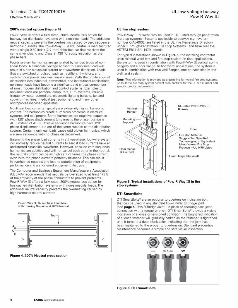
200% neutral option (Figure 4)
Pow-R-Way III offers a fully rated, 200% neutral bus option for busway fed distribution systems with nonlinear loads . The additional neutral capacity prevents the overheating caused by zero sequence harmonic currents . The Pow-R-Way III 200% neutral is manufactured with a single 0 .50 inch (12 .7 mm) thick bus bar that receives the same silver-plating and Class B, 130 °C Epoxy insulation as the phase bars .
Power system harmonics are generated by various types of non-linear loads . A sinusoidal voltage applied to a nonlinear load will result in a non-sinusoidal current and waveform distortion . Loads that are switched or pulsed, such as rectifiers, thyristors, and switch-mode power supplies, are nonlinear . With the proliferation of electronics into industrial, commercial, and institutional applications, nonlinear loads have become a significant and critical component of most modern distribution and control systems . Examples of nonlinear loads are personal computers, UPS systems, variable frequency motor controllers, electronic lighting ballasts, fax and copying machines, medical test equipment, and many other microprocessor-based apparatus .
Nonlinear load currents typically are extremely high in harmonic content . The harmonics create numerous problems in electrical systems and equipment . Some harmonics are negative sequence with 120° phase displacement (this means the phase rotation is ACB instead of ABC) . Positive sequence harmonics have 120° phase displacement, but are of the same rotation as the distribution system . Certain nonlinear loads cause odd triplen harmonics, which are zero sequence with no phase displacement .
Balancing the phase load currents in a three-phase, four-wire system will normally reduce neutral currents to zero if load currents have an undistorted sinusoidal waveform . However, because zero sequence harmonics are additive and will not cancel each other in the neutral, the neutral current can be as high as 1 .73 times the phase current, even with the phase currents perfectly balanced . This can result in overheated neutrals and lead to deterioration of equipment performance and a shortened equipment life cycle .
The Computer and Business Equipment Manufacturers Association (CBEMA) recommends that neutrals be oversized to at least 173% of the ampacity of the phase conductors to prevent problems . Pow-R-Way III offers a fully rated, 200% neutral bus option for busway fed distribution systems with non-sinusoidal loads . The additional neutral capacity prevents the overheating caused by high harmonic neutral currents .
Figure 4. 200% Neutral cross section
UL fire stop system
Pow-R-Way III busway may be used in UL Listed through-penetration fire stop systems . Systems applicable to busway e .g ., system number C-AJ-6002) are listed in the UL Fire Resistance Directory under “Through-Penetration Fire Stop Systems” and have met the ASTEM E814 (UL 1479) criteria .
For typical installations shown in Figure 5, the installing contractor uses mineral wool batt and fire stop sealant . In riser applications, the system is used in combination with Pow-R-Way III vertical spring hangers and a floor flange . In horizontal applications, the system is used in combination with two wall flanges, one on each side of the wall, and sealant .
otee:N This information is provided as a guideline for typical fire stop systems . Consult the fire stop system sealant manufacturer for the UL file number and specific product information .
Figure 5. Typical installations of Pow-R-Way III in fire stop systems
DTI SmartBolts
DTI SmartBolts® are an optional torque/tension indicating bolt that can be used in any standard Pow-R-Way III bridge joint (see page 5, Pow-R-Bridge Joint) . In place of checking each joint connection with a torque wrench, DTI SmartBolts® provide a visible indication of a loose or tensioned condition . The bright red indication of a loose fastener will gradually darken as the fastener is tightened until it turns to a deep black color, indicating that the joint has been tightened to the proper torque/tension . Standard preventive maintenance becomes a simple and safe visual inspection .
Figure 6. DTI SmartBolts
Top
Pow-R-Way III, Three-Phase Four-Wire with Housing Ground and 200% Neutral
AB
CN
Floor Flange12 Ga Steel
MountingSupport
VerticalHanger T
Floor
Fire stop MaterialSuggest 3m, Speci�edTechnologies, or EquivalentManufacturer Fire Stop Products—UL 1479 Listed
Floor Flange (Optional)
UL Listed Pow-R-Way IIIBusway

5
Technical Data TD01701001EEffective March 2017
UL low-voltage busway Pow-R-Way III
EATON www.eaton.com
Pow-R-Bridge (Figure 7)
Pow-R-Way III joint connections are made with the Pow-R-Bridge joint package, which is installed on each section of busway prior to shipment . A double-headed, torque-indicating bolt is provided to ensure that proper installation torque is achieved . Fall-away instruction tags are furnished on the torque-indicating bolt heads to allow for visual inspection from a distance . When the proper torque value is achieved, the top bolt head will shear off and allow the tag to fall to the floor . Any joint that is improperly torqued will retain the highly visible (caution yellow) tag at the bolt head .
The Pow-R-Bridge can provide an adjustment of ±0 .50 inch (12 .7 mm) at each joint . Over adjustment is prevented by the joint covers, which will only allow a 0 .50 inch (12 .7 mm) adjustment to be made and by stopping lances on the conductor bars of the Pow-R-Bridge . The non-rotating design of the Pow-R-Bridge maintains its configuration integrity when it has been removed from a section of busway . The conductors and insulators will not displace or swivel, making reinstallation of the Pow-R-Bridge quick and easy .
Outdoor Pow-R-Bridge (Figure 8)
Joint connections for outdoor feeder busway are made with a weatherized version of the Pow-R-Bridge joint . Aluminum water barriers, 1/16 inch (1 .6 mm) thick, are provided across the “T” and “T opposite” sides of both joint ends on each section of outdoor busway . Closed cell, neoprene gaskets are applied to the top of each water barrier and to the inside of the aluminum side access covers . The aluminum side access covers overlap the top and bottom access covers and bolt directly onto the end blocks . The outdoor Pow-R-Bridge has the same ±0 .50 inch (12 .7 mm) adjustability and features as the indoor unit and is UL Listed .
Table 2. Busway Pow-R-Bridge joint dimensions
UL 857 ampere rating
Figure 9 configurations
Dimensions in inches (mm)
W L
Copper225 A 4.50 (114.3) 7.38 (187.5)400 A 4.50 (114.3) 7.38 (187.5)600 A 4.50 (114.3) 7.38 (187.5)800 A 4.50 (114.3) 7.38 (187.5)1000 A 5.12 (130.0) 7.38 (187.5)1200 A 5.62 (142.8) 7.38 (187.5)1350 A 6.12 (155.4) 7.38 (187.5)1600 A 7.12 (180.9) 7.38 (187.5)2000 A 8.38 (212.9) 7.38 (187.5)2500 B 10.88 (276.4) 7.38 (187.5)3200 C 15.88 (403.4) 7.38 (187.5)4000 C 18.38 (466.9) 7.38 (187.5)5000 D 23.41 (594.6) 7.38 (187.5)Aluminum225 A 4.50 (114.3) 7.38 (187.5)400 A 4.50 (114.3) 7.38 (187.5)600 A 4.50 (114.3) 7.38 (187.5)800 A 5.62 (142.8) 7.38 (187.5)1000 A 6.12 (155.4) 7.38 (187.5)1200 A 7.12 (180.9) 7.38 (187.5)1350 A 8.38 (212.9) 7.38 (187.5)1600 B 9.12 (231.6) 7.38 (187.5)2000 B 10.88 (276.4) 7.38 (187.5)2500 C 18.38 (466.9) 7.38 (187.5)3200 D 19.88 (505.0) 7.38 (187.5)4000 D 23.41 (594.6) 7.38 (187.5)
Bridge JointPressure Plate(Top & Bottom)
Double-headedTorque-IndicatingBolt (Bottom)
BellevilleWasher
Ground Path Plate
Bridge JointRetainer Screw
Ground PathEnd Block
130º EpoxyInsulation
on Bars
.375-16 flg.Head Hex Bolt
(4 per Cover)
Joint Cover
GroundPath Label
Captive NutRetainer
Ground PathEnd Block
High StrengthGlass PolyesterInsulators
GroundPath ContactSurface
1/4-20 flg.Head Hex Bolt(4 per cover)
Figure 7. Indoor bridge joint features
Figure 8. Outdoor bridge joint features
Figure 9. Pow-R-Bridge joint
DANGER NOTICE
Ground Path Contact Surface
Gasketed Rear Joint Cover
Closed CellNeoprene GasketWater Barrier
Ground Path End Block
Double-HeadedJoint Torque Bolt
Bridge Joint Retainer Screw
BellevilleWasher
Pressure Plate(Top & Bottom)
Captive NutRetainer
Pow-R-Bridge Joint
Water Barrier
Ground PathEnd Block
Torque BoltAccess Opening
DrainHole Plug
GroundPath Label
Gasketed Front Joint Cover
Gasketed TopAccess Cover
DrainHole PlugGasketed Torque –
Bolt Access Cap(Top & Bottom)
GasketedCover Plate
Gasketed BottomAccess Cover
GasketedCover Plate
(L)

6
Technical Data TD01701001EEffective March 2017
UL low-voltage busway Pow-R-Way III
EATON www.eaton.com
Pow-R-Way III feeder busway (Figure 10 and Table 3)
• 225 to 5000 A copper• 225 to 4000 A aluminum
Straight sections of feeder busway can be supplied in any length, at 1/8 inch (3 .2 mm) increments, from a 16 .00 inch (406 .4 mm) minimum to a 10 ft (3 m) maximum . Figure 10 illustrates the configuration of feeder busway and Pow-R-Bridge for the available ampere ratings . See Table 3 below for reference to the proper configuration .
Table 3. Feeder busway configuration
UL 857 ampere rating
Figure 10 configurationCu Al
225 225 A400 400 A600 600 A800 — A
1000 — A1200 800 A1350 1000 A1600 1200 A2000 1350 A— 1600 B2500 2000 B3200 — C4000 2500 C— 3200 D5000 4000 D
Each section will include one, factory-installed Pow-R-Bridge mounted to the left end of the busway (with the “T” to the top, when viewing the bus from the “F” side) . Each Pow-R-Bridge will have a “T” label that must always match the “T” orientation of the busway .
16.00 Minimum(406.4)
Configuration A Top View1 Bar Per Phase
Configuration B Top View1 Bar Per Phase
Configuration C Top View2 Bars Per Phase
Configuration D Top View2 Bars Per Phase
T
CL CL
T
T
CL CL
T
T
CL CL
T
T
F
CL CL
F
T
T
F
CL CL
Front View
T
F
F F
F F
F F
Figure 10. Feeder busway

7
Technical Data TD01701001EEffective March 2017
UL low-voltage busway Pow-R-Way III
EATON www.eaton.com
Pow-R-Way III plug-in busway (Figure 11 and Table 4 and Table 5)
• 225 to 5000 A copper• 225 to 4000 A aluminum
Straight sections of plug-in busway are made only in 24 .00 inch (609 .6 mm) incremental lengths with a maximum length of 10 ft (3 m) . Figure 11 depicts the configuration of plug-in busway and Pow-R-Bridge for the available ampere ratings . See Table 4 below for reference to the proper configuration .
Table 4. Configuration
UL 857 ampere ratingFigure 10 configurationCu Al
225 225 A400 400 A600 600 A800 — A1000 — A1200 800 A1350 1000 A1600 1200 A2000 1350 A— 1600 B2500 2000 B3200 — C4000 2500 C— 3200 D5000 4000 D
Table 5 below illustrates the quantity of plug-in openings per side that are available per standard section .
Table 5. Number of plug-in openings
Dimensions in inches (mm) Number of plug-in openings
Duct length Front Back
24.00 (609.6) 1 148.00 (1219.2) 2 272.00 (1828.8) 3 396.00 (2438.4) 4 4120.00 (3048.0) 5 5
Each section will include one, factory-installed Pow-R-Bridge mounted to the left end of the busway (with the “T” label to the top, when viewing the bus from the “F” side) . Each Pow-R-Bridge will have a “T” label that must always match the “T” orientation of the busway .
Plug-in outlet
The plug-in outlet and cover are made from a durable, high-strength, polycarbonate material, which is rated as Class B, 130 °C, insulation . The plug-in cover is designed to protect the contact surfaces and to prevent the entry of dirt, dust, or moisture . The cover has a positive screw close feature that prohibits the opening of the cover without the use of a tool . The cover is also Utility “leadlock” sealable .
As a countermeasure to the effects of thermal expansion and mechanical vibration, the plug-in outlet is secured to the busway housing with high tensile strength locking hardware .
12.00(304.8)
24.00 Spacing(609.6)
12.00(304.8)
Configuration A Top View1 Bar Per Phase
T T
CL CL
CL CL
T T
12.00(304.8)
24.00 Spacing(609.6)
12.00(304.8)
Configuration B Top View1 Bar Per Phase
Configuration C Top View2 Bars Per Phase
Configuration D Top View2 Bars Per Phase
CL CL CL CL
12.00(304.8)
24.00 Spacing(609.6)
12.00(304.8)
CL CL
CL CL
12.00(304.8)
24.00 Spacing(609.6)
12.00(304.8)
12.00(304.8)
24.00 Spacing(609.6)
12.00(304.8)
CL CL CL
CL
CL CLT TF F
Front View
T T
T T
F F
F F
F F
F F
Figure 11. Plug-in busway
Figure 12. Plug-in outlet cover
Cover Can Be Hingedon Either Side
High StrengthPolycarbonateClass B 130ºC
PositiveScrew Close
Feature
Fingersafe Plug-in
Opening
LeadlockSealable
HingePins
A
C
N
B
G

8
Technical Data TD01701001EEffective March 2017
UL low-voltage busway Pow-R-Way III
EATON www.eaton.com
Electrical data
Table 6. Short-circuit rating
UL 857 ampere rating
6-cycle rms symmetrical short-circuit rating
Maximum Class L fuse needed to achieve 6-cycle rms series rating
Plug-in Feeder 100 kA 200 kA
Aluminum225 85,000 85,000 2000 1200400 85,000 85,000 2000 1200600 85,000 85,000 2000 1200800 100,000 100,000 — 25001000 100,000 100,000 — 25001200 125,000 125,000 — 25001350 150,000 150,000 — 40001600 150,000 150,000 — 40002000 150,000 150,000 — 40002500 200,000 200,000 — —3200 200,000 200,000 — —4000 200,000 200,000 — —Copper225 85,000 85,000 2000 1600400 85,000 85,000 2000 1600600 85,000 85,000 2000 1600800 85,000 85,000 2000 16001000 100,000 100,000 — 30001200 100,000 100,000 — 30001350 100,000 100,000 — 30001600 125,000 125,000 — 30002000 150,000 150,000 — 40002500 150,000 150,000 — 40003200 200,000 200,000 — —4000 200,000 200,000 — —5000 200,000 200,000 — —
Table 7. Resistance, reactance, and impedance—aluminum
Milliohms per 100 ft (30.5 m) line-to-neutral aluminum plug-in and feeder busway
UL 857 ampere rating Resistance R Reactance X Impedance Z
225 4.38 1.17 4.54400 4.38 1.17 4.54600 4.38 1.17 4.54800 2.67 0.99 2.841000 2.29 0.84 2.441200 1.76 0.64 1.871350 1.39 0.49 1.471600 1.25 0.43 1.322000 1.01 0.34 1.072500 0.71 0.27 0.763200 0.62 0.24 0.674000 0.50 0.19 0.54
Table 8. Resistance, reactance, and impedance—copper
Milliohms per 100 ft (30.5 m) line-to-neutral copper plug-in and feeder busway
UL 857 ampere rating Resistance R Reactance X Impedance Z
225 2.30 1.20 2.59400 2.30 1.20 2.59600 2.30 1.20 2.59800 2.30 1.20 2.591000 1.67 0.95 1.931200 1.39 0.78 1.601350 1.20 0.66 1.371600 0.94 0.50 1.072000 0.76 0.39 0.852500 0.55 0.26 0.613200 0.47 0.31 0.574000 0.38 0.24 0.455000 0.27 0.16 0.32
Table 9. Resistance values for integral housing ground (only) milliohms per 100 ft (30.5 m)
UL 857 ampere rating
Aluminum phase conductors
Copper phase conductors
225 1.04 1.04400 1.04 1.04600 1.04 1.04800 0.95 1.041000 0.92 0.991200 0.85 0.951350 0.72 0.921600 0.68 0.852000 0.61 0.722500 0.36 0.613200 0.34 0.434000 0.30 0.36
Derating table for higher ambient temperatures
Pow-R-Way III busway may be operated continuously at its assigned ratings without exceeding the maximum hot spot temperature rise of 55 °C, provided the ambient temperature does not exceed 40 °C . For higher ambient temperatures, the ratings should be reduced by applying the appropriate multiplier shown in the following table .
Table 10. Higher ambient temperature multipliers
Ambient temperature Multiplier
40 °C (104 °F) 1.0045 °C (113 °F) 0.9550 °C (122 °F) 0.9055 °C (131 °F) 0.8560 °C (140 °F) 0.8065 °C (149 °F) 0.7470 °C (158 °F) 0.67

9
Technical Data TD01701001EEffective March 2017
UL low-voltage busway Pow-R-Way III
EATON www.eaton.com
Electrical data (continued)Line-to-line voltage drop
The table below gives average three-phase voltage drop per 100 ft (30 .5 m) at rated current and varying power factor . Line-to-neutral voltage drop is obtained by multiplying the line value by 0 .577 .
Table 11. Line-to-line voltage drop
UL 857 ampere rating
Percent power factor
0 10 20 30 40 50 60 70 80 90 100
Copper225 0.47 0.56 0.64 0.72 0.79 0.85 0.91 0.96 1.00 1.01 0.90400 0.83 0.99 1.14 1.27 1.40 1.52 1.62 1.71 1.78 1.80 1.60600 1.25 1.48 1.70 1.91 2.10 2.28 2.44 2.57 2.66 2.70 2.39800 1.67 1.98 2.27 2.55 2.80 3.04 3.25 3.42 3.55 3.60 3.191000 1.65 1.93 2.20 2.45 2.68 2.88 3.07 3.21 3.32 3.34 2.911200 1.62 1.90 2.17 2.42 2.65 2.86 3.04 3.19 3.30 3.32 2.911350 1.54 1.82 2.08 2.32 2.54 2.75 2.93 3.08 3.18 3.21 2.821600 1.40 1.65 1.90 2.12 2.33 2.52 2.69 2.84 2.94 2.97 2.622000 1.35 1.61 1.85 2.08 2.29 2.49 2.66 2.81 2.92 2.96 2.632500 1.16 1.39 1.62 1.83 2.02 2.20 2.37 2.51 2.62 2.66 2.403200 1.73 1.98 2.22 2.44 2.64 2.81 2.96 3.07 3.14 3.12 2.634000 1.68 1.93 2.17 2.39 2.59 2.77 2.92 3.04 3.11 3.10 2.635000 1.44 1.67 1.89 2.09 2.28 2.44 2.59 2.71 2.78 2.79 2.40Aluminum225 0.46 0.63 0.79 0.95 1.10 1.25 1.39 1.52 1.64 1.74 1.71400 0.81 1.11 1.40 1.69 1.96 2.22 2.47 2.71 2.92 3.09 3.04600 1.22 1.67 2.11 2.53 2.94 3.33 3.71 4.06 4.38 4.63 4.56800 1.38 1.74 2.09 2.42 2.74 3.04 3.32 3.57 3.79 3.93 3.701000 1.46 1.85 2.22 2.58 2.93 3.25 3.55 3.82 4.05 4.21 3.981200 1.34 1.70 2.04 2.37 2.69 2.99 3.26 3.52 3.73 3.87 3.661350 1.16 1.48 1.79 2.08 2.37 2.63 2.88 3.11 3.30 3.44 3.261600 1.21 1.55 1.88 2.20 2.50 2.79 3.05 3.30 3.50 3.65 3.472000 1.18 1.53 1.87 2.19 2.50 2.79 3.06 3.31 3.53 3.69 3.522500 1.20 1.50 1.79 2.06 2.33 2.58 2.81 3.01 3.18 3.30 3.083200 1.35 1.69 2.01 2.33 2.62 2.90 3.16 3.39 3.59 3.71 3.484000 1.32 1.66 2.00 2.31 2.62 2.90 3.17 3.41 3.61 3.75 3.53
otee:N Voltage drop = √3 I (R cos ø + X sin ø) Volts/100 ft (30 .5 m)—concentrated load, where cos ø = power factor .
otee:N For plug-in distributed loads, divide the voltage drop by 2 . See IEEE Standard 141-13-8 .3 .
otee:N Actual voltage drop for loads less than full rated current and different lengths may be calculated by multiplying the values from Table 11 by (actual/rated current) x (actual length/100 ft [30 .5 m]) .

10
Technical Data TD01701001EEffective March 2017
UL low-voltage busway Pow-R-Way III
EATON www.eaton.com
Electrical data (continued)Housing ground vs. internal ground
Eaton’s Pow-R-Way III busway offers a variety of grounding options . Two of which are 50% integral housing ground and 50% internal ground .
The 50% internal ground option has a separate ground conductor internal to the housing, which is rated 50% of the phase conductor .
The integral housing ground is where the extruded aluminum housing is used as the ground path and no internal ground conductor is provided . The housing is UL Listed as a 50% integral ground path . This type of ground path is as effective as a ground conductor as an internal ground bar . Table 12 shows a cross-sectional comparison between the aluminum housing and internal ground bar . The integral housing ground provides a larger ground path that is over 100% of the cross-sectional area of the phase conductors . Figure 13 illustrates the difference between the two grounding options .
Table 12. Housing ground vs. Internal ground comparison
UL 857 ampere rating
Bar size (in)Bar per phase
Cross-sectional area (sq in)
Internal ground
Housing groundCu Al
225 225 0.13 x 1.63 1 0.20 2.37400 400 0.13 x 1.63 1 0.20 2.48600 600 0.13 x 1.63 1 0.20 2.48800 — 0.13 x 1.63 1 0.20 2.481000 — 0.13 x 2.25 1 0.28 2.541200 800 0.13 x 2.75 1 0.34 2.691350 1000 0.13 x 3.25 1 0.41 2.831600 1200 0.13 x 4.25 1 0.53 3.112000 1350 0.13 x 5.50 1 0.69 3.46— 1600 0.13 x 6.25 1 0.78 3.682500 2000 0.13 x 8.00 1 1.00 4.173200 — 0.13 x 4.25 2 1.06 6.224000 2500 0.13 x 5.50 2 1.38 6.92— 3200 0.13 x 6.25 2 1.56 7.365000 4000 0.13 x 8.00 2 2.00 8.34
Integral Housing Ground
Internal Ground Bar
Figure 13. Housing ground vs. internal ground

11
Technical Data TD01701001EEffective March 2017
UL low-voltage busway Pow-R-Way III
EATON www.eaton.com
Physical dataDimensions—bus bar and housing
Table 13. Three-wire with no neutral
UL 857 ampere rating
Phase bar size (depth and width) inches (mm)
Bar per phase
Conductor configuration and housing size (width x height) inches (mm)
50% integral housing ground 3WH
50% internal ground bus 3WHG a
50% internal isolated ground 3WI
Figure 14 config. bCu Al
225 225 0.25 x 1.62 (6.4 x 41.1) 1 4.75 x 4.38 (120.7 x 111.3) 4.75 x 4.50 (120.7 x 114.3) 4.75 x 4.55 (120.7 x 115.6) A400 400 0.25 x 1.62 (6.4 x 41.1) 1 4.75 x 4.38 (120.7 x 111.3) 4.75 x 4.50 (120.7 x 114.3) 4.75 x 4.55 (120.7 x 115.6) A600 600 0.25 x 1.62 (6.4 x 41.1) 1 4.75 x 4.38 (120.7 x 111.3) 4.75 x 4.50 (120.7 x 114.3) 4.75 x 4.55 (120.7 x 115.6) A800 — 0.25 x 1.62 (6.4 x 41.1) 1 4.75 x 4.38 (120.7 x 111.3) 4.75 x 4.50 (120.7 x 114.3) 4.75 x 4.55 (120.7 x 115.6) A1000 — 0.25 x 2.25 (6.4 x 57.2) 1 5.38 x 4.38 (136.7 x 111.3) 5.38 x 4.50 (136.7 x 114.3) 5.38 x 4.55 (136.7 x 115.6) A1200 800 0.25 x 2.75 (6.4 x 69.9) 1 5.88 x 4.38 (149.3 x 111.3) 5.88 x 4.50 (149.3 x 114.3) 5.88 x 4.55 (149.3 x 115.6) A1350 1000 0.25 x 3.25 (6.4 x 82.6) 1 6.38 x 4.38 (162.1 x 111.3) 6.38 x 4.50 (162.1 x 114.3) 6.38 x 4.55 (162.1 x 115.6) A1600 1200 0.25 x 4.25 (6.4 x 108.0) 1 7.38 x 4.38 (187.5 x 111.3) 7.38 x 4.50 (187.5 x 114.3) 7.38 x 4.55 (187.5 x 115.6) A2000 1350 0.25 x 5.50 (6.4 x 139.7) 1 8.64 x 4.38 (219.5 x 111.3) 8.64 x 4.50 (219.5 x 114.3) 8.64 x 4.55 (219.5 x 115.6) A— 1600 0.25 x 6.25 (6.4 x 158.8) 1 9.40 x 4.38 (238.8 x 111.3) 9.40 x 4.50 (238.8 x 114.3) 9.40 x 4.55 (238.8 x 115.6) A2500 2000 0.25 x 8.00 (6.4 x 203.2) 1 11.17 x 4.38 (283.7 x 111.3) 11.17 x 4.50 (283.7 x 114.3) 11.17 x 4.55 (283.7 x 115.6) A3200 — 0.25 x 4.25 (6.4 x 108.0) 2 16.14 x 4.38 (410.0 x 111.3) 16.14 x 4.50 (410.0 x 114.3) 16.14 x 4.55 (410.0 x 115.6) B4000 2500 0.25 x 5.50 (6.4 x 139.7) 2 18.64 x 4.38 (473.5 x 111.3) 18.64 x 4.50 (473.5 x 114.3) 18.64 x 4.55 (473.5 x 115.6) B— 3200 0.25 x 6.25 (6.4 x 158.8) 2 20.16 x 4.38 (512.1 x 111.3) 20.16 x 4.50 (512.1 x 114.3) 20.16 x 4.55 (512.1 x 115.6) B5000 4000 0.25 x 8.00 (6.4 x 203.2) 2 23.70 x 4.38 (602.0 x 111.3) 23.70 x 4.50 (602.0 x 114.3) 23.70 x 4.55 (602.0 x 115.6) B
a100% ground available with same dimensions, which uses 50% internal ground and 50% internal housing ground.bRefer to Figure 13 on Page 12 for configuration A and B.
Table 14. Four-wire with 100% neutral
UL 857 ampere rating Phase and neutral bar
size (depth and width) inches (mm)
Bar per phase
Conductor configuration and housing size (width x height) inches (mm)
50% integral housing ground 4WH
50% internal ground bus 4WHG a
50% internal isolated ground 4WI
Figure 14 config. bCu Al
225 225 0.25 x 1.62 (6.4 x 41.1) 1 4.75 x 4.38 (120.7 x 111.3) 4.75 x 4.50 (120.7 x 114.3) 4.75 x 4.55 (120.7 x 115.6) A400 400 0.25 x 1.62 (6.4 x 41.1) 1 4.75 x 4.38 (120.7 x 111.3) 4.75 x 4.50 (120.7 x 114.3) 4.75 x 4.55 (120.7 x 115.6) A600 600 0.25 x 1.62 (6.4 x 41.1) 1 4.75 x 4.38 (120.7 x 111.3) 4.75 x 4.50 (120.7 x 114.3) 4.75 x 4.55 (120.7 x 115.6) A800 — 0.25 x 1.62 (6.4 x 41.1) 1 4.75 x 4.38 (120.7 x 111.3) 4.75 x 4.50 (120.7 x 114.3) 4.75 x 4.55 (120.7 x 115.6) A1000 — 0.25 x 2.25 (6.4 x 57.2) 1 5.38 x 4.38 (136.7 x 111.3) 5.38 x 4.50 (136.7 x 114.3) 5.38 x 4.55 (136.7 x 115.6) A1200 800 0.25 x 2.75 (6.4 x 69.9) 1 5.88 x 4.38 (149.3 x 111.3) 5.88 x 4.50 (149.3 x 114.3) 5.88 x 4.55 (149.3 x 115.6) A1350 1000 0.25 x 3.25 (6.4 x 82.6) 1 6.38 x 4.38 (162.1 x 111.3) 6.38 x 4.50 (162.1 x 114.3) 6.38 x 4.55 (162.1 x 115.6) A1600 1200 0.25 x 4.25 (6.4 x 108.0) 1 7.38 x 4.38 (187.5 x 111.3) 7.38 x 4.50 (187.5 x 114.3) 7.38 x 4.55 (187.5 x 115.6) A2000 1350 0.25 x 5.50 (6.4 x 139.7) 1 8.64 x 4.38 (219.5 x 111.3) 8.64 x 4.50 (219.5 x 114.3) 8.64 x 4.55 (219.5 x 115.6) A— 1600 0.25 x 6.25 (6.4 x 158.8) 1 9.40 x 4.38 (238.8 x 111.3) 9.40 x 4.50 (238.8 x 114.3) 9.40 x 4.55 (238.8 x 115.6) A2500 2000 0.25 x 8.00 (6.4 x 203.2) 1 11.17 x 4.38 (283.7 x 111.3) 11.17 x 4.50 (283.7 x 114.3) 11.17 x 4.55 (283.7 x 115.6) A3200 — 0.25 x 4.25 (6.4 x 108.0) 2 16.14 x 4.38 (410.0 x 111.3) 16.14 x 4.50 (410.0 x 114.3) 16.14 x 4.55 (410.0 x 115.6) B4000 2500 0.25 x 5.50 (6.4 x 139.7) 2 18.64 x 4.38 (473.5 x 111.3) 18.64 x 4.50 (473.5 x 114.3) 18.64 x 4.55 (473.5 x 115.6) B— 3200 0.25 x 6.25 (6.4 x 158.8) 2 20.16 x 4.38 (512.1 x 111.3) 20.16 x 4.50 (512.1 x 114.3) 20.16 x 4.55 (512.1 x 115.6) B5000 4000 0.25 x 8.00 (6.4 x 203.2) 2 23.70 x 4.38 (602.0 x 111.3) 23.70 x 4.50 (602.0 x 114.3) 23.70 x 4.55 (602.0 x 115.6) B
a100% ground available with same dimensions, which uses 50% internal ground and 50% internal housing ground.bRefer to Figure 14 on page 12 for configuration A and B.

12
Technical Data TD01701001EEffective March 2017
UL low-voltage busway Pow-R-Way III
EATON www.eaton.com
Physical data (continued)Dimensions—bus bar and housing (continued)
Table 15. Four-wire with 200% neutral
UL 857 ampere rating Phase bar size (depth and width) inches (mm) a
Bar per phase
Conductor configuration and housing size (width x height) inches (mm)
50% integral housing ground 4WH
50% internal ground bus 4WHG b
50% internal isolated ground 4WI
Figure 14 config. cCu Al
225 225 0.25 x 1.62 (6.4 x 41.1) 1 4.75 x 4.92 (120.7 x 125.0) 4.75 x 5.05 (120.7 x 128.2) 4.75 x 5.10 (120.7 x 129.5) A400 400 0.25 x 1.62 (6.4 x 41.1) 1 4.75 x 4.92 (120.7 x 125.0) 4.75 x 5.05 (120.7 x 128.2) 4.75 x 5.10 (120.7 x 129.5) A600 600 0.25 x 1.62 (6.4 x 41.1) 1 4.75 x 4.92 (120.7 x 125.0) 4.75 x 5.05 (120.7 x 128.2) 4.75 x 5.10 (120.7 x 129.5) A800 — 0.25 x 1.62 (6.4 x 41.1) 1 4.75 x 4.92 (120.7 x 125.0) 4.75 x 5.05 (120.7 x 128.2) 4.75 x 5.10 (120.7 x 129.5) A1000 — 0.25 x 2.25 (6.4 x 57.2) 1 5.38 x 4.92 (136.7 x 125.0) 5.38 x 5.05 (136.7 x 128.2) 5.38 x 5.10 (136.7 x 129.5) A1200 800 0.25 x 2.75 (6.4 x 69.9) 1 5.88 x 4.92 (149.3 x 125.0) 5.88 x 5.05 (149.3 x 128.2) 5.88 x 5.10 (149.3 x 129.5) A1350 1000 0.25 x 3.25 (6.4 x 82.6) 1 6.38 x 4.92 (162.1 x 125.0) 6.38 x 5.05 (162.1 x 128.2) 6.38 x 5.10 (162.1 x 129.5) A1600 1200 0.25 x 4.25 (6.4 x 108.0) 1 7.38 x 4.92 (187.5 x 125.0) 7.38 x 5.05 (187.5 x 128.2) 7.38 x 5.10 (187.5 x 129.5) A2000 1350 0.25 x 5.50 (6.4 x 139.7) 1 8.64 x 4.92 (219.5 x 125.0) 8.64 x 5.05 (219.5 x 128.2) 8.64 x 5.10 (219.5 x 129.5) A— 1600 0.25 x 6.25 (6.4 x 158.8) 1 9.40 x 4.92 (238.8 x 125.0) 9.40 x 5.05 (238.8 x 128.2) 9.40 x 5.10 (238.8 x 129.5) A2500 2000 0.25 x 8.00 (6.4 x 203.2) 1 11.17 x 4.92 (283.7 x 125.0) 11.17 x 5.05 (283.7 x 128.2) 11.17 x 5.10 (283.7 x 129.5) A3200 — 0.25 x 4.25 (6.4 x 108.0) 2 16.14 x 4.92 (410.0 x 125.0) 16.14 x 5.05 (410.0 x 128.2) 16.14 x 5.10 (410.0 x 129.5) B4000 2500 0.25 x 5.50 (6.4 x 139.7) 2 18.64 x 4.92 (473.5 x 125.0) 18.64 x 5.05 (473.5 x 128.2) 18.64 x 5.10 (473.5 x 129.5) B— 3200 0.25 x 6.25 (6.4 x 158.8) 2 20.16 x 4.92 (512.1 x 125.0) 20.16 x 5.05 (512.1 x 128.2) 20.16 x 5.10 (512.1 x 129.5) B5000 4000 0.25 x 8.00 (6.4 x 203.2) 2 23.70 x 4.92 (602.0 x 125.0) 23.70 x 5.05 (602.0 x 128.2) 23.70 x 5.10 (602.0 x 129.5) B
aNeutral bar is 0.50 (12.7) x width shown.b100% ground available with same dimensions, which uses 50% internal ground and 50% integral housing ground.cRefer to Figure 14 for Configuration A and B.
Figure 14. Pow-R-Way III cross-section dimensions
225 to 2000 Ampere Aluminum225 to 2500 Ampere Copper
2500 to 4000 Ampere Aluminum3200 to 5000 Ampere Copper
Width
Height
Configuration A
Width
Height
Configuration B
ABCCN
ABCN
ABCCN

13
Technical Data TD01701001EEffective March 2017
UL low-voltage busway Pow-R-Way III
EATON www.eaton.com
Physical data (continued)Weights
Table 16. Weight (pounds/ft) and current density (amperes/in2)
UL 857 ampere rating
UL 857 Current density amperes/in2
Weight—including integral housing ground (pounds/ft)
Three-wireFour-wire 100% neutral
Four-wire 200% neutral Add for internal ground
Cu Al Cu Al Cu Al Cu Al Cu Al Cu Al
225 225 554 554 8 5 10 6 11 7 0.78 0.23400 400 985 985 8 5 10 6 11 7 0.78 0.23600 600 1477 — 8 — 10 — 11 — 0.78 —800 — 1969 1477 8 5 10 6 11 7 0.78 0.231000 — 1778 — 10 — 12 — 14 — 1.08 —1200 800 1745 1164 12 6 15 7 17 8 1.33 0.401350 1000 1662 1231 14 7 17 8 20 9 1.57 0.471600 1200 1506 1129 17 8 21 10 25 11 2.05 0.622000 1350 1455 982 23 11 28 12 33 13 2.66 0.80— 1600 — 1024 — 12 — 13 — 15 — 0.912500 2000 1250 1000 29 14 36 16 42 18 3.87 1.173200 — 1505 — 34 — 42 — 49 — 4.11 —4000 2500 1455 909 45 21 56 24 66 27 5.32 1.61— 3200 — 960 — 23 — 26 — 29 — 1.835000 4000 1250 1000 63 28 72 32 85 36 7.74 2.35
Table 17. Weight (kg/m) and current density (amperes/cm2)
UL 857 ampere rating
UL 857 current density amperes/cm2
Weight—including integral housing ground (kg/m)
Three-wireFour-wire 100% neutral
Four-wire 200% neutral Add for internal ground
Cu Al Cu Al Cu Al Cu Al Cu Al Cu Al
225 225 86 86 12 7 15 9 17 11 1.17 0.35400 400 153 153 12 7 15 9 17 11 1.17 0.35600 600 229 — 12 — 15 — 17 — 1.17 —800 — 305 229 12 7 15 9 17 11 1.17 0.351000 — 276 — 15 — 18 — 21 — 1.62 —1200 800 270 180 18 9 22 11 26 12 1.98 0.601350 1000 258 191 21 11 25 12 30 14 2.34 0.711600 1200 233 175 25 12 32 15 37 16 3.06 0.922000 1350 226 152 34 16 42 18 49 20 3.96 1.20— 1600 — 159 — 18 — 20 — 22 — 1.362500 2000 194 155 43 21 54 24 63 27 5.76 1.753200 — 233 — 51 — 63 — 73 — 6.12 —4000 2500 226 140 67 32 83 36 98 40 7.92 2.40— 3200 — 149 — 34 — 39 — 43 — 2.735000 4000 194 155 94 42 108 48 126 54 11.53 3.50

14
Technical Data TD01701001EEffective March 2017
UL low-voltage busway Pow-R-Way III
EATON www.eaton.com
Physical data (continued)
Table 18. Ampere ratings needed to be at or below 1000 amperes/sq in density
UL 857 ampere rating
Bar size
Copper Aluminum
Standard density
1000 A/sq in density
Adjusted rating
Standard density
1000 A/sq in density
Adjusted ratingCu Al
225 225 1.62 556 556 None 556 556 None400 400 1.62 988 988 None 988 988 None600 600 1.62 1481 873 1200 — — —800 — 1.62 1975 985 1350 1481 873 8001000 — 2.25 1778 941 1600 — — —1200 800 2.75 1745 873 2000 1164 985 10001350 1000 3.25 1662 982 2000 1231 941 12001600 1200 4.25 1506 800 2500 1129 873 13502000 1350 5.50 1455 1000 2500 982 864 1600— 1600 6.25 — — — 1024 800 20002500 2000 8.00 1250 909 4000 1000 1000 None3200 — 2.00 x 4.25 1506 800 5000 — — —4000 2500 2.00 x 5.50 1455 1000 5000 909 909 None— 3200 2.00 x 6.25 — — — 1024 800 40005000 4000 2.00 x 8.00 1250 N/A N/A 1000 1000 None
Application note
The above table is meant to help the user and specifier select the higher busway ratings to meet the performance specification of a current density value no higher than 1000 A per sq inch . The current density values of our standard busway offerings based upon temperature rise are listed in the 4th and 7th columns of the table . These ratings are UL Listed and labeled, and safe to apply . However, certain jurisdictions or applications require a better margin of safety, and choose to use a 1000 A/sq inch density standard .
When the lower than standard densities are required, such as 1000 A/sq inch, then the only option is to oversize the busway from the standard bar sizes and ampacity ratings . Oversizing provides more bus bar material in cross-sectional area, and results in lower current densities and lower temperature rises for a given value of load current .
By example, take the case of 1600 A copper busway . The standard product uses a bar size of 0 .25 x 4 .25 inches (1 .0625 sq inch in area) and which results in 1506 A sq inch density (calculated by 1600 A/1 .0625 sq inch = 1506 A/sq inches), as listed in the table . If a project or application using bus runs expected to carry 1600 A of load current stipulated that the current densities experienced by the busway should be no greater than 1000 A/sq inch, then oversizing to busway bars used in the standard 2500 A rating using 0 .25 x 8 .00 inch bars (2 .0 sq inch area) yields a current density of 1600 A/2 .0 sq inches . 800 A/sq inches for the 1600 A of load current .
Why not just oversize to 2000 A busway? The 2000 A bar size is 0 .25 x 5 .50 inches or 1 .375 sq inches . Computing the new density yields 1600 A/1 .375 sq inch = 1164 A/sq inch, which is higher than the desired value of no greater density than 1000 A/sq inch .
Therefore, the table provides a quick method of determining the ampacity of busway required to meet current density values no greater than 1000 A/sq inch for given values of load current . The most important columns of data are the 1st, 7th, and 10th .
Eaton warrants that the Pow-R-Way III product will perform as intended regardless of the method of selection, either temperature rise only or current density . Eaton encourages specifiers who use current density as the criteria for busway selection to select and specify the busway ratings recommended in the above table under the Adjusted Rating column, and to not rely upon the contractors or bidders to resolve the matter in the later stages of a project . If sizing busway is strictly based upon current density, do not specify or use the standard ampacity values based upon the UL and NEMA temperature rise standard on Contract Drawings .

15
Technical Data TD01701001EEffective March 2017
UL low-voltage busway Pow-R-Way III
EATON www.eaton.com
Physical data (continued)Fittings
There is a fitting to meet every application need: flanges, elbows, offsets, tees, cable tap boxes, weatherheads, transformer connections, power take-off sections, reducers, adapter cubicles, expansion joints, and end closures .
These fittings, along with standard and minimum dimensions, are described on the following pages .
When making field measurements and layouts, it should be remembered that the dimensions are given from the centerline of the Pow-R-Bridge .
The relationship of fittings to straight lengths (forward, rearward, upward, and downward) is illustrated in Figure 15 .
All straight lengths and fittings are marked with a “T” label and an “F” label . The “T” and “F” locations will also be noted on the construction, or the as-built, Eaton drawings furnished . When installing the busway, the “T” and “F” markings of each section must match. Failure to do so will result in an improper installation with the phase bars out of sequence.
Figure 15. Typical busway components
Figure 16. “T” and “F” orientation for fittings
Rearward Upward
Forward
Downward
90º Phase Transposition
Upward/DownwardCorner Joint
Forward/RearwardCorner Joint
Forward/Rearward
Tee
Center CableTap Box
Weatherhead Expansion Joint
180º PhaseTransposition
TransformerThroat
Forward/Rearward Elbow
ProtectedReducer
Floor Flange
Plug-inBus
Bolt-onUnit
End Closer
In-LinePower
Take-Off
Built-inPower
Take-Off
Plug-inUnit
Wall Flange
Offset
Upward/Downward
Tee
Switchboard
Switchboard
Transformer
End Cable Tap Box
OutdoorIndoor

16
Technical Data TD01701001EEffective March 2017
UL low-voltage busway Pow-R-Way III
EATON www.eaton.com
Physical data (continued)Traditional indoor and outdoor elbows (Figure 17)
Elbows are used to make 90° changes in the direction of busway runs . The four types that are available are forward, rearward, upward, and downward . See minimum leg lengths listed for each type in Table 19 and Table 20 .
otee:N All dimensions are to the centerline of the Pow-R-Bridge .
Figure 17. Traditional elbows
Corner joint elbows (Figure 18)
The Pow-R-Way III corner joint elbow can be installed in areas where a traditional 90° turn could never have been accomplished before .
Pow-R-Way III corner joint elbows can solve any serious pathway problem and contribute to successful layouts with minimal space requirements . The corner joint elbow is UL Listed for indoor applications only and is also certified for seismic withstand capability to worst-case, Zone 4 levels .
otee:N All dimensions are to the centerline of the corner joint connection .
Figure 18. Corner joint elbows (for indoor applications only)
Table 19. Forward and rearward elbows
UL 857 ampere rating Dimensions in inches (mm)
Cu Al Minimum leg lengths X
225 225 13.00 (330.2)400 400 13.00 (330.2)600 600 13.00 (330.2)800 — 13.00 (330.2)1000 — 13.00 (330.2)1200 800 13.50 (342.9)1350 1000 13.50 (342.9)1600 1200 14.00 (355.6)2000 1350 14.50 (368.3)— 1600 15.00 (381.0)2500 2000 16.00 (406.4)3200 — 18.50 (469.9)4000 2500 19.50 (495.3)— 3200 20.50 (520.7)5000 4000 22.50 (571.5)
Table 20. Upward and downward elbows
UL 857 ampere rating
Dimensions in inches (mm)
Minimum leg lengths X
Cu Al Upward Downward
225 225 10.00 (254.0) 13.00 (330.2)400 400 10.00 (254.0) 13.00 (330.2)600 600 10.00 (254.0) 13.00 (330.2)800 — 10.00 (254.0) 13.00 (330.2)1000 — 10.00 (254.0) 13.00 (330.2)1200 800 10.00 (254.0) 13.00 (330.2)1350 1000 10.00 (254.0) 13.00 (330.2)1600 1200 10.00 (254.0) 13.00 (330.2)2000 1350 10.00 (254.0) 13.00 (330.2)— 1600 10.00 (254.0) 13.00 (330.2)2500 2000 10.00 (254.0) 13.00 (330.2)3200 — 12.00 (304.8) 13.00 (330.2)4000 2500 12.00 (304.8) 13.00 (330.2)— 3200 12.00 (304.8) 13.00 (330.2)5000 4000 12.00 (304.8) 13.00 (330.2)
Table 21. Forward/rearward corner joints
UL 857 ampere rating Dimensions in inches (mm)
Cu Al X Y
225 225 0.94 (23.9) 5.38 (136.7)400 400 0.94 (23.9) 5.38 (136.7)600 600 0.94 (23.9) 5.38 (136.7)800 — 0.94 (23.9) 5.38 (136.7)1000 — 1.25 (31.8) 5.69 (144.5)1200 800 1.50 (38.1) 5.94 (150.9)1350 1000 1.75 (44.5) 6.19 (157.2)1600 1200 2.25 (57.2) 6.69 (169.9)2000 1350 2.88 (73.2) 7.31 (185.7)— 1600 3.25 (82.6) 7.70 (195.6)2500 2000 4.12 (104.7) 8.57 (217.7)3200 — 6.64 (168.7) 11.07 (281.2)4000 2500 7.89 (200.4) 12.32 (312.9)— 3200 8.65 (219.7) 13.08 (332.2)5000 4000 10.42 (264.7) 14.85 (377.2)
X
CLCC CLCC
X
Forward Downward
X
XUpward
X
X
Rearward
CLCCX
CLCC CLCC
CLCC
CLCC CLCC
CLCC
CC
CLCC
CLCC
CLCC
X
CLCC Upward
XCLCC Y
Forward
CLCC CLCCCLCC
XCLCC Y
Rearward
CLCC CLCC
CLCC
CLCC
Y
Downward
CLCCCLCC
CLCC
CLCC
Y
CCLLCCCCLCC
CLCC
X

17
Technical Data TD01701001EEffective March 2017
UL low-voltage busway Pow-R-Way III
EATON www.eaton.com
Table 22. Upward/downward corner joints
UL 857 ampere rating
Dimensions in inches (mm)
Housing ground Internal ground Isolated ground
Cu Al X Y X Y X Y
Three-wire225 225 4.70 (119.6) 4.35 (110.5) 4.77 (121.2) 4.41 (112.0) 5.27 (133.9) 4.43 (112.5)400 400 4.70 (119.6) 4.35 (110.5) 4.77 (121.2) 4.41 (112.0) 5.27 (133.9) 4.43 (112.5)600 600 4.70 (119.6) 4.35 (110.5) 4.77 (121.2) 4.41 (112.0) 5.27 (133.9) 4.43 (112.5)800 — 4.70 (119.6) 4.35 (110.5) 4.77 (121.2) 4.41 (112.0) 5.27 (133.9) 4.43 (112.5)1000 — 4.70 (119.6) 4.35 (110.5) 4.77 (121.2) 4.41 (112.0) 5.27 (133.9) 4.43 (112.5)1200 800 4.70 (119.6) 4.35 (110.5) 4.77 (121.2) 4.41 (112.0) 5.27 (133.9) 4.43 (112.5)1350 1000 4.70 (119.6) 4.35 (110.5) 4.77 (121.2) 4.41 (112.0) 5.27 (133.9) 4.43 (112.5)1600 1200 4.70 (119.6) 4.35 (110.5) 4.77 (121.2) 4.41 (112.0) 5.27 (133.9) 4.43 (112.5)2000 1350 4.70 (119.6) 4.35 (110.5) 4.77 (121.2) 4.41 (112.0) 5.27 (133.9) 4.43 (112.5)— 1600 4.70 (119.6) 4.35 (110.5) 4.77 (121.2) 4.41 (112.0) 5.27 (133.9) 4.43 (112.5)2500 2000 4.70 (119.6) 4.35 (110.5) 4.77 (121.2) 4.41 (112.0) 5.27 (133.9) 4.43 (112.5)3200 — 4.70 (119.6) 4.35 (110.5) 4.77 (121.2) 4.41 (112.0) 5.27 (133.9) 4.43 (112.5)4000 2500 4.70 (119.6) 4.35 (110.5) 4.77 (121.2) 4.41 (112.0) 5.27 (133.9) 4.43 (112.5)— 3200 4.70 (119.6) 4.35 (110.5) 4.77 (121.2) 4.41 (112.0) 5.27 (133.9) 4.43 (112.5)5000 4000 4.70 (119.6) 4.35 (110.5) 4.77 (121.2) 4.41 (112.0) 5.27 (133.9) 4.43 (112.5)Four-wire (100%)225 225 4.71 (119.6) 5.00 (127.0) 4.77 (121.2) 5.07 (128.8) 5.28 (134.1) 5.09 (129.3)400 400 4.71 (119.6) 5.00 (127.0) 4.77 (121.2) 5.07 (128.8) 5.28 (134.1) 5.09 (129.3)600 600 4.71 (119.6) 5.00 (127.0) 4.77 (121.2) 5.07 (128.8) 5.28 (134.1) 5.09 (129.3)800 — 4.71 (119.6) 5.00 (127.0) 4.77 (121.2) 5.07 (128.8) 5.28 (134.1) 5.09 (129.3)1000 — 4.71 (119.6) 5.00 (127.0) 4.77 (121.2) 5.07 (128.8) 5.28 (134.1) 5.09 (129.3)1200 800 4.71 (119.6) 5.00 (127.0) 4.77 (121.2) 5.07 (128.8) 5.28 (134.1) 5.09 (129.3)1350 1000 4.71 (119.6) 5.00 (127.0) 4.77 (121.2) 5.07 (128.8) 5.28 (134.1) 5.09 (129.3)1600 1200 4.71 (119.6) 5.00 (127.0) 4.77 (121.2) 5.07 (128.8) 5.28 (134.1) 5.09 (129.3)2000 1350 4.71 (119.6) 5.00 (127.0) 4.77 (121.2) 5.07 (128.8) 5.28 (134.1) 5.09 (129.3)— 1600 4.71 (119.6) 5.00 (127.0) 4.77 (121.2) 5.07 (128.8) 5.28 (134.1) 5.09 (129.3)2500 2000 4.71 (119.6) 5.00 (127.0) 4.77 (121.2) 5.07 (128.8) 5.28 (134.1) 5.09 (129.3)3200 — 4.71 (119.6) 5.00 (127.0) 4.77 (121.2) 5.07 (128.8) 5.28 (134.1) 5.09 (129.3)4000 2500 4.71 (119.6) 5.00 (127.0) 4.77 (121.2) 5.07 (128.8) 5.28 (134.1) 5.09 (129.3)— 3200 4.71 (119.6) 5.00 (127.0) 4.77 (121.2) 5.07 (128.8) 5.28 (134.1) 5.09 (129.3)5000 4000 4.71 (119.6) 5.00 (127.0) 4.77 (121.2) 5.07 (128.8) 5.28 (134.1) 5.09 (129.3)Four-wire (200%)225 225 4.98 (126.5) 5.10 (129.5) 5.04 (128.0) 5.17 (131.3) 5.55 (141.0) 5.19 (131.8)400 400 4.98 (126.5) 5.10 (129.5) 5.04 (128.0) 5.17 (131.3) 5.55 (141.0) 5.19 (131.8)600 600 4.98 (126.5) 5.10 (129.5) 5.04 (128.0) 5.17 (131.3) 5.55 (141.0) 5.19 (131.8)800 — 4.98 (126.5) 5.10 (129.5) 5.04 (128.0) 5.17 (131.3) 5.55 (141.0) 5.19 (131.8)1000 — 4.98 (126.5) 5.10 (129.5) 5.04 (128.0) 5.17 (131.3) 5.55 (141.0) 5.19 (131.8)1200 800 4.98 (126.5) 5.10 (129.5) 5.04 (128.0) 5.17 (131.3) 5.55 (141.0) 5.19 (131.8)1350 1000 4.98 (126.5) 5.10 (129.5) 5.04 (128.0) 5.17 (131.3) 5.55 (141.0) 5.19 (131.8)1600 1200 4.98 (126.5) 5.10 (129.5) 5.04 (128.0) 5.17 (131.3) 5.55 (141.0) 5.19 (131.8)2000 1350 4.98 (126.5) 5.10 (129.5) 5.04 (128.0) 5.17 (131.3) 5.55 (141.0) 5.19 (131.8)— 1600 4.98 (126.5) 5.10 (129.5) 5.04 (128.0) 5.17 (131.3) 5.55 (141.0) 5.19 (131.8)2500 2000 4.98 (126.5) 5.10 (129.5) 5.04 (128.0) 5.17 (131.3) 5.55 (141.0) 5.19 (131.8)3200 — 4.98 (126.5) 5.10 (129.5) 5.04 (128.0) 5.17 (131.3) 5.55 (141.0) 5.19 (131.8)4000 2500 4.98 (126.5) 5.10 (129.5) 5.04 (128.0) 5.17 (131.3) 5.55 (141.0) 5.19 (131.8)— 3200 4.98 (126.5) 5.10 (129.5) 5.04 (128.0) 5.17 (131.3) 5.55 (141.0) 5.19 (131.8)5000 4000 4.98 (126.5) 5.10 (129.5) 5.04 (128.0) 5.17 (131.3) 5.55 (141.0) 5.19 (131.8)

18
Technical Data TD01701001EEffective March 2017
UL low-voltage busway Pow-R-Way III
EATON www.eaton.com
Physical data (continued)Special angle elbows
Special angle elbows are traditional elbows that allow the direction of the busway runs to change at angles greater than 90° . They allow easy routing through non-traditional corridors . The four types offered are forward, rearward, upward, and downward . See minimum leg lengths for each type listed in Table 23 and Table 24 .
Table 23. Forward and rearward elbows
UL 857 ampere rating Dimensions in inches (mm)
Cu Al Minimum leg lengths X
225 225 13.00 (330.2)400 400 13.00 (330.2)600 600 13.00 (330.2)800 — 13.00 (330.2)1000 — 13.00 (330.2)1200 800 13.50 (342.9)1350 1000 13.50 (342.9)1600 1200 14.00 (355.6)2000 1350 14.50 (368.3)— 1600 15.00 (381.0)2500 2000 16.00 (406.4)3200 — 18.50 (469.9)4000 2500 19.50 (495.3)— 3200 20.50 (520.7)5000 4000 22.50 (571.5)
Table 24. Upward and downward elbows
UL 857 ampere rating
Dimensions in inches (mm)
Minimum leg lengths X
Cu Al Upward Downward
225 225 10.00 (254.0) 13.00 (330.2)400 400 10.00 (254.0) 13.00 (330.2)600 600 10.00 (254.0) 13.00 (330.2)800 — 10.00 (254.0) 13.00 (330.2)1000 — 10.00 (254.0) 13.00 (330.2)1200 800 10.00 (254.0) 13.00 (330.2)1350 1000 10.00 (254.0) 13.00 (330.2)1600 1200 10.00 (254.0) 13.00 (330.2)2000 1350 10.00 (254.0) 13.00 (330.2)— 1600 10.00 (254.0) 13.00 (330.2)2500 2000 10.00 (254.0) 13.00 (330.2)3200 — 12.00 (304.8) 13.00 (330.2)4000 2500 12.00 (304.8) 13.00 (330.2)— 3200 12.00 (304.8) 13.00 (330.2)5000 4000 12.00 (304.8) 13.00 (330.2)
Forward
Rearward
Upward
Downward
Figure 19. Special angle elbows

19
Technical Data TD01701001EEffective March 2017
UL low-voltage busway Pow-R-Way III
EATON www.eaton.com
Physical data (continued)Standard and flush flanges (Figure 20)
Flanges provide a direct connection to low-voltage switchgear, switchboards, motor control centers, and other apparatus . Cutout dimensions and drilling plans are provided with the customer drawings and it is the responsibility of the switchgear manufacturer to provide the opening, flange drillings, connecting hardware, and bus risers in their equipment . For proper coordination between busway and other equipment, detailed drawings, including switchgear orientation, must accompany the order . A standard flange can be supplied to the left or right of a section, as required . A flush flange is used when the busway must lay close to the top of a switchboard . The edge of the busway is 1 .25 inches (31 .8 mm) from the top of the switchboard .
otee:N All dimensions are to the centerline of the Pow-R-Bridge .
Table 25. Switchboard flanges
UL 857 ampere rating Dimensions in inches (mm)
Cu AlFlush flange min. leg length X
Standard flange min. leg length X
225 225 15.00 (381.0) 12.00 (304.8)400 400 15.00 (381.0) 12.00 (304.8)600 600 15.00 (381.0) 12.00 (304.8)800 — 15.00 (381.0) 12.00 (304.8)1000 — 15.00 (381.0) 12.00 (304.8)1200 800 15.00 (381.0) 12.00 (304.8)1350 1000 15.00 (381.0) 12.00 (304.8)1600 1200 15.00 (381.0) 12.00 (304.8)2000 1350 15.00 (381.0) 12.00 (304.8)— 1600 15.00 (381.0) 12.00 (304.8)2500 2000 15.00 (381.0) 12.00 (304.8)3200 — 15.00 (381.0) 12.00 (304.8)4000 2500 15.00 (381.0) 12.00 (304.8)— 3200 15.00 (381.0) 12.00 (304.8)5000 4000 15.00 (381.0) 12.00 (304.8)
Vault flanges
Vault flanges are used to enter a utility vault for termination to the utility transformer . Each vault flange is custom designed to meet each specific utility specification . Vault flanges may look similar to those shown in Figure 21 . Please consult the factory for specific dimensions based upon utility specifications .
Figure 20. Flanges
Figure 21. Vault flanges
1.00(25.4)
A
B
N
C
B
A
G
C

20
Technical Data TD01701001EEffective March 2017
UL low-voltage busway Pow-R-Way III
EATON www.eaton.com
Physical data (continued)Elbow flanges (Figure 22)
An elbow flange is a combination of a standard elbow and a standard flange fabricated into a single fitting . Elbow flanges are typically used when the minimum leg lengths for either the standard elbow or standard flange cannot be maintained . Minimum leg lengths are listed in Table 26 and Table 27 .
otee:N All dimensions are to the centerline of the Pow-R-Bridge .
Table 26. Forward and rearward elbow flanges
UL 857 ampere rating Minimum dimensions in inches (mm)
Cu Al Joint leg X Flange leg Y
225 225 13.00 (330.2) 8.75 (222.3)400 400 13.00 (330.2) 8.75 (222.3)600 600 13.00 (330.2) 8.75 (222.3)800 — 13.00 (330.2) 8.75 (222.3)1000 — 13.00 (330.2) 8.75 (222.3)1200 800 13.50 (342.9) 9.25 (235.0)1350 1000 13.50 (342.9) 9.25 (235.0)1600 1200 14.00 (355.6) 9.75 (247.7)2000 1350 14.50 (368.3) 10.25 (260.4)— 1600 15.00 (381.0) 10.75 (273.1)2500 2000 16.00 (406.4) 11.75 (298.5)3200 — 18.50 (469.9) 14.00 (355.6)4000 2500 19.50 (495.3) 15.25 (387.4)— 3200 20.50 (520.7) 16.00 (406.4)5000 4000 22.50 (571.5) 17.75 (450.9)
Table 27. Upward and downward elbow flanges
UL 857 ampere rating
Minimum dimensions in inches (mm)
Joint leg X Flange leg Y
Cu Al Up Down Up Down
225 225 10.00 (254.0) 13.00 (330.2) 5.75 (146.1) 8.75 (222.3)400 400 10.00 (254.0) 13.00 (330.2) 5.75 (146.1) 8.75 (222.3)
600 600 10.00 (254.0) 13.00 (330.2) 5.75 (146.1) 8.75 (222.3)800 — 10.00 (254.0) 13.00 (330.2) 5.75 (146.1) 8.75 (222.3)1000 — 10.00 (254.0) 13.00 (330.2) 5.75 (146.1) 8.75 (222.3)1200 800 10.00 (254.0) 13.00 (330.2) 5.75 (146.1) 8.75 (222.3)1350 1000 10.00 (254.0) 13.00 (330.2) 5.75 (146.1) 8.75 (222.3)1600 1200 10.00 (254.0) 13.00 (330.2) 5.75 (146.1) 8.75 (222.3)2000 1350 10.00 (254.0) 13.00 (330.2) 5.75 (146.1) 8.75 (222.3)— 1600 10.00 (254.0) 13.00 (330.2) 5.75 (146.1) 8.75 (222.3)2500 2000 10.00 (254.0) 13.00 (330.2) 5.75 (146.1) 8.75 (222.3)3200 — 12.00 (304.8) 13.00 (330.2) 7.75 (196.9) 8.75 (222.3)4000 2500 12.00 (304.8) 13.00 (330.2) 7.75 (196.9) 8.75 (222.3)— 3200 12.00 (304.8) 13.00 (330.2) 7.75 (196.9) 8.75 (222.3)5000 4000 12.00 (304.8) 13.00 (330.2) 7.75 (196.9) 8.75 (222.3)
Y
Upward ElbowRight Flange
X
CL
CL
CL
Y
Forward ElbowRight Flange
X
CL
CL
CL
YX
Rearward ElbowRight Flange
CL
CLCL
YDownward ElbowRight Flange
X
CLCL
Figure 22. Elbow flanges

21
Technical Data TD01701001EEffective March 2017
UL low-voltage busway Pow-R-Way III
EATON www.eaton.com
Physical data (continued)Offsets (Figure 23)
An offset is used to avoid obstacles and to conform to the building’s structure . It is two elbows fabricated into a single fitting for use where space restrictions prohibit the use of two standard 90° elbows . The minimum leg lengths are listed in Table 28 and Table 29 .
otee:N All dimensions are to the centerline of the Pow-R-Bridge .
Table 28. Forward and rearward offsets
UL 857 ampere rating
Minimum dimensions Y in inches (mm)Cu Al
225 225 13.00 (330.2)400 400 13.00 (330.2)600 600 13.00 (330.2)800 — 13.00 (330.2)1000 — 13.00 (330.2)1200 800 13.50 (342.9)1350 1000 13.50 (342.9)1600 1200 14.00 (355.6)2000 1350 14.50 (368.3)— 1600 15.00 (381.0)2500 2000 16.00 (406.4)3200 — 18.50 (469.9)4000 2500 19.50 (495.3)— 3200 20.50 (520.7)5000 4000 22.50 (571.5)
Table 29. Upward and downward offsets
UL 857 ampere rating
Minimum dimensions in inches (mm)
Upward Downward
Cu Al Y Z Y Z
225 225 10.00 (254.0) 13.00 (330.2) 13.00 (330.2) 10.00 (254.0)400 400 10.00 (254.0) 13.00 (330.2) 13.00 (330.2) 10.00 (254.0)600 600 10.00 (254.0) 13.00 (330.2) 13.00 (330.2) 10.00 (254.0)800 — 10.00 (254.0) 13.00 (330.2) 13.00 (330.2) 10.00 (254.0)1000 — 10.00 (254.0) 13.00 (330.2) 13.00 (330.2) 10.00 (254.0)1200 800 10.00 (254.0) 13.00 (330.2) 13.00 (330.2) 10.00 (254.0)1350 1000 10.00 (254.0) 13.00 (330.2) 13.00 (330.2) 10.00 (254.0)1600 1200 10.00 (254.0) 13.00 (330.2) 13.00 (330.2) 10.00 (254.0)2000 1350 10.00 (254.0) 13.00 (330.2) 13.00 (330.2) 10.00 (254.0)— 1600 10.00 (254.0) 13.00 (330.2) 13.00 (330.2) 10.00 (254.0)2500 2000 10.00 (254.0) 13.00 (330.2) 13.00 (330.2) 10.00 (254.0)3200 — 12.00 (304.8) 13.00 (330.2) 13.00 (330.2) 12.00 (304.8)4000 2500 12.00 (304.8) 13.00 (330.2) 13.00 (330.2) 12.00 (304.8)— 3200 12.00 (304.8) 13.00 (330.2) 13.00 (330.2) 12.00 (304.8)5000 4000 12.00 (304.8) 13.00 (330.2) 13.00 (330.2) 12.00 (304.8)
Y
Y
3.00(76.2)(Minimum)
Rearward
CL
CL
CL
CL
CL
3.00(76.2)(Minimum)
Y
Forward
CL
YCL
CL
CL
Y
Downward
3.00(76.2)(Minimum)
CL
CL
CL
CL
CL
Z
T
Z
Upward
CL
CL
CL
CL
Y
T
3.00(76.2)
(Minimum)
Figure 23. Offsets

22
Technical Data TD01701001EEffective March 2017
UL low-voltage busway Pow-R-Way III
EATON www.eaton.com
Physical data (continued)Combination offsets (Figure 24)
Combination offsets are used to conform to the building’s structure and change direction, using a small amount of space . They are two different oriented elbows fabricated into a single fitting . Forward or rearward directions are determined by the “T” and “F” locations . Please refer to page 15 . Minimum leg lengths are listed in Table 30 .
Table 30. Combination offsets
UL 857 ampere rating
Dimensions in inches (mm)
Three-wire/ four-wire
Four-wire 200% N
Cu Al X Y Z Z
Upward/forward/rearward225 225 10.00 (254.0) 13.00 (330.2) 7.00 (177.8) 7.00 (177.8)400 400 10.00 (254.0) 13.00 (330.2) 7.00 (177.8) 7.00 (177.8)600 600 10.00 (254.0) 13.00 (330.2) 7.00 (177.8) 7.00 (177.8)800 — 10.00 (254.0) 13.00 (330.2) 7.00 (177.8) 7.00 (177.8)1000 — 10.00 (254.0) 13.00 (330.2) 7.00 (177.8) 7.50 (190.5)1200 800 10.00 (254.0) 13.50 (342.9) 7.50 (190.5) 7.50 (190.5)1350 1000 10.00 (254.0) 13.50 (342.9) 7.50 (190.5) 8.00 (203.2)1600 1200 10.00 (254.0) 14.00 (355.6) 8.00 (203.2) 8.50 (215.9)2000 1350 10.00 (254.0) 14.50 (368.3) 9.00 (228.6) 9.00 (228.6)— 1600 10.00 (254.0) 15.00 (381.0) 9.00 (228.6) 9.50 (241.3)2500 2000 10.00 (254.0) 16.00 (406.4) 10.00 (254.0) 10.50 (266.7)3200 — 12.00 (304.8) 18.50 (469.9) 12.50 (317.5) 13.00 (330.2)4000 2500 12.00 (304.8) 19.50 (495.3) 14.00 (355.6) 14.00 (355.6)— 3200 12.00 (304.8) 20.50 (520.7) 14.50 (368.3) 15.00 (381.0)5000 4000 12.00 (304.8) 22.50 (571.5) 16.50 (419.1) 16.50 (419.1)Downward/forward/rearward225 225 13.00 (330.2) 13.00 (330.2) 7.00 (177.8) 7.00 (177.8)400 400 13.00 (330.2) 13.00 (330.2) 7.00 (177.8) 7.00 (177.8)600 600 13.00 (330.2) 13.00 (330.2) 7.00 (177.8) 7.00 (177.8)800 — 13.00 (330.2) 13.00 (330.2) 7.00 (177.8) 7.00 (177.8)1000 — 13.00 (330.2) 13.00 (330.2) 7.00 (177.8) 7.50 (190.5)1200 800 13.00 (330.2) 13.50 (342.9) 7.50 (190.5) 7.50 (190.5)1350 1000 13.00 (330.2) 13.50 (342.9) 7.50 (190.5) 8.00 (203.2)1600 1200 13.00 (330.2) 14.00 (355.6) 8.00 (203.2) 8.50 (215.9)2000 1350 13.00 (330.2) 14.50 (368.3) 9.00 (228.6) 9.00 (228.6)— 1600 13.00 (330.2) 15.00 (381.0) 9.00 (228.6) 9.50 (241.3)2500 2000 13.00 (330.2) 16.00 (406.4) 10.00 (254.0) 10.50 (266.7)3200 — 13.00 (330.2) 18.50 (469.9) 12.50 (317.5) 13.00 (330.2)4000 2500 13.00 (330.2) 19.50 (495.3) 14.00 (355.6) 14.00 (355.6)— 3200 13.00 (330.2) 20.50 (520.7) 14.50 (368.3) 15.00 (381.0)5000 4000 13.00 (330.2) 22.50 (571.5) 16.50 (419.1) 16.50 (419.1)
X
Z
YT T
YFF T
T
T
F X
F Z
FFF
CLCC
CLCC
CLCC
CLCC CLCC
CLCC
CLCCCLCC
CLCC
CLCC
LCLL
X
T T
Z
FFFF
F
X
FFFFFFFFFFF
Z
T
T
F
CLCC
CLCC
CLCC
CLCC
CLCC
CLCC
CLCC
CLCC
CLCC
CLCC
CLCC
Figure 24. Combination offsets

23
Technical Data TD01701001EEffective March 2017
UL low-voltage busway Pow-R-Way III
EATON www.eaton.com
Physical data (continued)Tees (Figure 25)
A tee is a busway fitting suitable for connection in three directions . The minimum leg lengths are shown in Table 31 and Table 32 .
Table 31. Forward and rearward tees
UL 857 ampere rating Minimum leg dimensions in inches (mm)
Cu Al X A Y B C
225 225 13.00 (330.2)
— 13.00 (330.2)
— —
400 400 13.00 (330.2)
— 13.00 (330.2)
— —
600 600 13.00 (330.2)
— 13.00 (330.2)
— —
800 — 13.00 (330.2)
— 13.00 (330.2)
— —
1000 — 13.00 (330.2)
— 13.00 (330.2)
— —
1200 800 13.50 (342.9)
— 13.50 (342.9)
— —
1350 1000 13.50 (342.9)
— 13.50 (342.9)
— —
1600 1200 14.00 (355.6)
— 14.00 (355.6)
— —
2000 1350 14.50 (368.3)
— 14.50 (368.3)
— —
— 1600 15.00 (381.0)
— 15.00 (381.0)
— —
2500 2000 16.00 (406.4)
— 16.00 (406.4)
— —
3200 — 27.25 (692.2)
8.00 (203.2)
26.38 (670.1)
19.39 (492.5)
21.12 (536.4)
4000 2500 28.50 (723.9)
8.00 (203.2)
27.62 (701.6)
21.88 (555.8)
23.63 (600.2)
— 3200 29.25 (743.0)
8.00 (203.2)
28.38 (720.9)
23.41 (594.6)
25.12 (638.0)
5000 4000 31.00 (787.4)
8.00 (203.2)
30.12 (765.1)
26.94 (684.3)
28.63 (727.2)
otee:N All dimensions are to the centerline of the Pow-R-Bridge .
Table 32. Upward and downward tees
UL 857 ampere rating Minimum leg dimensions in inches (mm)
Cu Al X A Y B C
225 225 21.25 (539.8)
12.25 (311.2)
25.50 (647.7)
5.00 (127.0)
9.25 (235.0)
400 400 21.25 (539.8)
12.25 (311.2)
25.50 (647.7)
5.00 (127.0)
9.25 (235.0)
600 600 21.25 (539.8)
12.25 (311.2)
25.50 (647.7)
5.00 (127.0)
9.25 (235.0)
800 — 21.25 (539.8)
12.25 (311.2)
25.50 (647.7)
5.00 (127.0)
9.25 (235.0)
1000 — 21.88 (555.8)
12.25 (311.2)
25.50 (647.7)
5.62 (142.7)
10.50 (266.7)
1200 800 22.38 (568.5)
12.25 (311.2)
25.50 (647.7)
6.12 (155.4)
11.50 (292.1)
1350 1000 22.88 (581.2)
12.25 (311.2)
25.50 (647.7)
6.62 (168.1)
12.50 (317.5)
1600 1200 23.88 (606.6)
12.25 (311.2)
25.50 (647.7)
7.62 (193.5)
14.50 (368.3)
2000 1350 25.12 (638.1)
12.25 (311.2)
25.50 (647.7)
8.65 (219.7)
17.00 (431.8)
— 1600 25.88 (657.4)
12.25 (311.2)
25.50 (647.7)
9.65 (245.1)
18.50 (470.0)
Table 32. Upward and downward tees (continued)
UL 857 ampere rating Minimum leg dimensions in inches (mm)
Cu Al X A Y B C
2500 2000 27.62 (701.6)
12.25 (311.2)
25.50 (647.7)
11.42 (290.1)
22.00 (558.8)
3200 — 23.88 (606.6)
12.25 (311.2)
25.50 (647.7)
16.38 (416.1)
14.50 (368.3)
4000 2500 25.12 (638.1)
12.25 (311.2)
25.50 (647.7)
18.65 (473.7)
17.00 (473.7)
— 3200 25.88 (637.4)
12.25 (311.2)
25.50 (647.7)
20.41 (518.4)
18.50 (470.0)
5000 4000 27.62 (701.6)
12.25 (311.2)
25.50 (647.7)
23.94 (608.1)
22.00 (558.8)
Figure 25. Tees
Forward
Rearward
Upward
Downward
X
X
Y
X
X
Y
X
X
Y
X
X
Y
CL
CL
CL
CL
CL
CL
CL
CL
CL
CL
CL
CL
CL
CL
CL
CL
CL
CL
CL
CL
B C
A
B C
A

24
Technical Data TD01701001EEffective March 2017
UL low-voltage busway Pow-R-Way III
EATON www.eaton.com
Physical data (continued)Crosses (Figure 26)
A cross is a busway fitting suitable for connection in four directions . It is applied when a bus run must branch off in three directions, all in the same plane .
Table 33. Forward and rearward crosses
UL 857 ampere rating Minimum leg dimensions in inches (mm)
Cu Al X Y
225 225 13.00 (330.2) 13.00 (330.2)400 400 13.00 (330.2) 13.00 (330.2)600 600 13.00 (330.2) 13.00 (330.2)800 — 13.00 (330.2) 13.00 (330.2)1000 — 13.00 (330.2) 13.00 (330.2)1200 800 13.50 (342.9) 13.50 (342.9)1350 1000 13.50 (342.9) 13.50 (342.9)1600 1200 14.00 (355.6) 14.00 (355.6)2000 1350 14.50 (368.3) 14.50 (368.3)— 1600 15.00 (381.0) 15.00 (381.0)2500 2000 16.00 (406.4) 16.00 (406.4)3200 — 23.00 (584.2) 23.00 (584.2)4000 2500 24.00 (609.6) 24.00 (609.6)— 3200 25.00 (635.0) 25.00 (635.0)5000 4000 26.00 (660.4) 26.00 (660.4)
otee:N All dimensions are to the centerline of the Pow-R-Bridge . For 5000 A Cu and 4000 A Al, these are fixed leg length dimensions .
Table 34. Upward and downward crosses
UL 857 ampere rating Minimum leg dimensions in inches (mm)
Cu Al X Y
225 225 21.25 (539.8) 25.50 (647.7)400 400 21.25 (539.8) 25.50 (647.7)600 600 21.25 (539.8) 25.50 (647.7)800 — 21.25 (539.8) 25.50 (647.7)1000 — 21.88 (555.8) 25.50 (647.7)1200 800 22.38 (568.5) 25.50 (647.7)1350 1000 22.88 (581.2) 25.50 (647.7)1600 1200 23.88 (606.6) 25.50 (647.7)2000 1350 25.12 (638.1) 25.50 (647.7)— 1600 25.88 (657.4) 25.50 (647.7)2500 2000 27.62 (701.6) 25.50 (647.7)3200 — 23.88 (606.6) 25.50 (647.7)4000 2500 25.12 (638.1) 25.50 (647.7)— 3200 25.88 (637.4) 25.50 (647.7)5000 4000 27.62 (701.6) 25.50 (647.7)
Forward – Rearward
Upward – Downward
Figure 26. Crosses

25
Technical Data TD01701001EEffective March 2017
UL low-voltage busway Pow-R-Way III
EATON www.eaton.com
Physical data (continued)End cable tap box (Figure 27)
End cable tap boxes are used to feed a run of busway with cable and conduit or where loads served by busway are connected without the need for overcurrent protection . For indoor applications, the “T” side, side opposite “T,” and the end panel are removable for access to the lugs . For outdoor applications, these panels are gasketed to prevent moisture from entering . In addition, the outdoor end cable tap boxes are provided with removable gasketed side access panels located on the “F” and side opposite “F” for more accessibility to the lugs . Removable side access panels are available on indoor cable tap boxes upon request .
otee:N All dimensions are to the centerline of the Pow-R-Bridge .
�
“T” SideRemovableIndoor
12.00(304.8)
Side Opposite “T”Removable Indoor
�17.50(444.5)
15.00(381.0)
GasketedAccess Coveron Front andBack of Boxfor OutdoorTap BoxesStandard
� 32.50(825.5)
30.00(762.0)
38.00(965.2)
DMin.GutterSpace
of Duct
LC
LC
A
(Minimum)
Figure 27. End cable tap box
aDimension D: For mechanical lugs = 21.34 inches (542.0 mm). For compression lugs = 19.44 inches (493.8 mm).
b200% neutral.
Table 35. End cable tap box dimension
Copper AluminumQuantity of mechanical terminals, range—one #4 (20 mm2)— 600 kcmil (300 mm2), two 1/0 (50 mm2)–250 kcmil (120 mm2) a
UL 857 ampere rating
Dimension A in inches (mm) b
UL 857 ampere rating
Dimension A in inches (mm) b
Copper Aluminum
G c P d N e G c P d N e
225 12.00 (304.8) 225 12.00 (304.8) 1 2 4 1 2 4400 12.00 (304.8) 400 12.00 (304.8) 1 2 4 1 2 4 600 12.00 (304.8) 600 12.00 (304.8) 1 2 4 — — —800 12.00 (304.8) — 12.00 (304.8) 2 3 5 1 2 41000 12.00 (304.8) — 12.00 (304.8) 2 3 6 — — —1200 12.00 (304.8) 800 12.00 (304.8) 2 4 8 2 3 51350 12.00 (304.8) 1000 12.00 (304.8) 2 4 8 2 3 61600 20.50 (520.7) 1200 12.00 (304.8) 3 5 9 2 4 82000 20.50 (520.7) 1350 20.50 (520.7) 3 6 12 2 — 8— — 1600 24.50 (622.3) — — — 3 5 92500 24.50 (622.3) 2000 24.50 (622.3) 4 8 16 3 6 123200 30.50 (774.5) — — 5 9 18 — — —4000 45.00 (1143.0) 2500 30.50 (774.5) 6 12 24 4 8 16— — 3200 30.50 (774.5) — — — 5 9 185000 45.00 (1143.0) 4000 45.00 (1143.0) 7 15 30 6 12 24
aFor compression lugs, factory provides provisions only.bAll dimensions shown in Figure 27 remain constant regardless of system wiring configuration.cDenotes quantity of terminals per ground bus.dDenotes quantity of terminals per phase and 100% neutral bus.eDenotes quantity of terminals per 200% neutral bus option.

26
Technical Data TD01701001EEffective March 2017
UL low-voltage busway Pow-R-Way III
EATON www.eaton.com
Physical data (continued)Center cable tap box (Figure 28)
Center cable tap boxes are used to center feed a run of busway with cable and conduit or where loads served by the busway are connected without the need for overcurrent protection . For indoor applications, the “T” side, side opposite “T,” and the end panel are removable for access to the lugs . For outdoor applications, these panels are gasketed to prevent moisture from entering . In addition, the outdoor center cable tap boxes are provided with removable gasketed access panels located on the front and back for more accessibility to the lugs .
otee:N All dimensions are to the centerline of the Pow-R-Bridge .
Table 36. Center tap box details—dimension C
Dimension C in inches (mm)
Copper225–1350 A 1600–2000 A 2500 A 3200 A 4000–5000 A3.63 (92.2) 4.75 (120.7) 6.00 (152.4) 10.75 (273.1) 12.25 (311.2)Aluminum225–1000 A 1200–1350 A 160–2000 A 2500–3200 A 4000 A3.63 (92.2) 4.75 (120.7) 6.00 (152.4) 10.75 (273.1) 12.25 (311.2)
�
�
�
Figure 28. Center cable tap box
aDimension D: For mechanical lugs = 21.34 inches (542.0 mm). For compression lugs = 19.25 inches (489.0 mm).
b200% neutral.
Table 37. Center tap box details—dimensions A and B
Copper AluminumQuantity of mechanical terminals, range—one #4 (20 mm2)— 600 kcmil (300 mm2), two 1/0 (50 mm2)—250 kcmil (120 mm2) a
UL 857 ampere rating
Dimensions in inches (mm) UL 857 ampere rating
Dimensions in inches (mm) Copper Aluminum
A b B b A b B b G c P d N e G c P d N e
225 16.50 (419.1) 40.00 (1016.0) 225 16.50 (419.1) 40.00 (1016.0) 1 2 4 1 2 4400 16.50 (419.1) 40.00 (1016.0) 400 16.50 (419.1) 40.00 (1016.0) 1 2 4 1 2 4600 16.50 (419.1) 40.00 (1016.0) 600 16.50 (419.1) 40.00 (1016.0) 1 2 4 — — —800 16.50 (419.1) 40.00 (1016.0) — 16.50 (419.1) 40.00 (1016.0) 2 3 5 1 2 41000 16.50 (419.1) 40.00 (1016.0) — 16.50 (419.1) 40.00 (1016.0) 2 3 6 — — —1200 16.50 (419.1) 40.00 (1016.0) 800 16.50 (419.1) 40.00 (1016.0) 2 4 8 2 3 51350 16.50 (419.1) 40.00 (1016.0) 1000 16.50 (419.1) 40.00 (1016.0) 2 4 8 2 3 61600 20.50 (520.7) 42.50 (1079.5) 1200 20.50 (520.7) 42.50 (1079.5) 3 5 9 2 4 82000 20.50 (520.7) 42.50 (1079.5) 1350 20.50 (520.7) 42.50 (1079.5) 3 6 12 2 4 8— — — 1600 24.50 (622.3) 45.00 (1143.0) — — — 3 5 92500 24.50 (622.3) 45.00 (1143.0) 2000 24.50 (622.3) 45.00 (1143.0) 4 8 16 3 6 123200 30.38 (774.5) 58.00 (1473.2) — — — 5 9 18 — — —4000 45.00 (1143.0) 60.50 (1536.7) 2500 30.38 (771.7) 58.00 (1473.0) 6 12 24 4 8 16— — — 3200 30.38 (771.7) 58.00 (1473.0) — — — 5 9 185000 45.00 (1143.0) 60.50 (1536.7) 4000 45.00 (1143.0) 60.50 (1536.7) 7 15 30 6 12 24
aFor compression lugs, factory provides provisions only.bAll dimensions shown in Figure 28 remain constant regardless of system wiring configuration.cDenotes quantity of terminals per ground bus.dDenotes quantity of terminals per phase and 100% neutral bus.eDenotes quantity of terminals per 200% neutral bus option.
27
Technical Data TD01701001EEffective March 2017
UL low-voltage busway Pow-R-Way III
EATON www.eaton.com
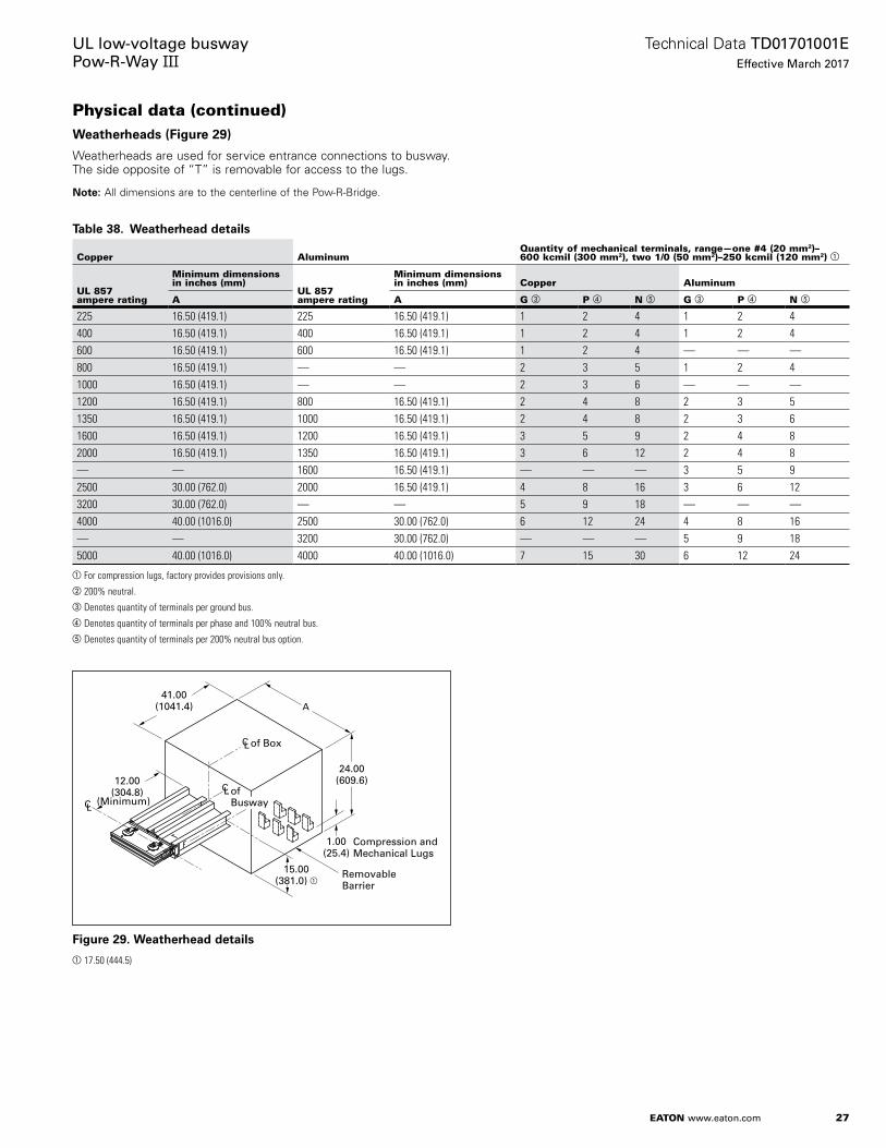
Physical data (continued)Weatherheads (Figure 29)
Weatherheads are used for service entrance connections to busway . The side opposite of “T” is removable for access to the lugs .
otee:N All dimensions are to the centerline of the Pow-R-Bridge .
Table 38. Weatherhead details
Copper AluminumQuantity of mechanical terminals, range—one #4 (20 mm2)– 600 kcmil (300 mm2), two 1/0 (50 mm2)–250 kcmil (120 mm2) a
UL 857 ampere rating
Minimum dimensions in inches (mm)
UL 857 ampere rating
Minimum dimensions in inches (mm) Copper Aluminum
A A G c P d N e G c P d N e
225 16.50 (419.1) 225 16.50 (419.1) 1 2 4 1 2 4400 16.50 (419.1) 400 16.50 (419.1) 1 2 4 1 2 4600 16.50 (419.1) 600 16.50 (419.1) 1 2 4 — — —800 16.50 (419.1) — — 2 3 5 1 2 41000 16.50 (419.1) — — 2 3 6 — — —1200 16.50 (419.1) 800 16.50 (419.1) 2 4 8 2 3 51350 16.50 (419.1) 1000 16.50 (419.1) 2 4 8 2 3 61600 16.50 (419.1) 1200 16.50 (419.1) 3 5 9 2 4 82000 16.50 (419.1) 1350 16.50 (419.1) 3 6 12 2 4 8— — 1600 16.50 (419.1) — — — 3 5 92500 30.00 (762.0) 2000 16.50 (419.1) 4 8 16 3 6 123200 30.00 (762.0) — — 5 9 18 — — —4000 40.00 (1016.0) 2500 30.00 (762.0) 6 12 24 4 8 16— — 3200 30.00 (762.0) — — — 5 9 185000 40.00 (1016.0) 4000 40.00 (1016.0) 7 15 30 6 12 24
aFor compression lugs, factory provides provisions only.b200% neutral.cDenotes quantity of terminals per ground bus.dDenotes quantity of terminals per phase and 100% neutral bus.eDenotes quantity of terminals per 200% neutral bus option.
Figure 29. Weatherhead details
a17.50 (444.5)
CL12.00
(304.8)
15.00(381.0) a
Removable Barrier
of Busway
Compression andMechanical Lugs
24.00(609.6)
41.00(1041.4)
of Box
A
CL
CL
1.00(25.4)
(Minimum)

28
Technical Data TD01701001EEffective March 2017
UL low-voltage busway Pow-R-Way III
EATON www.eaton.com
Physical data (continued)Expansion joints (Figure 30)
Expansion joints accommodate the expansion and contraction of bus bars with respect to the enclosure . They compensate for the difference in the coefficient of expansion of the aluminum housing and the copper or aluminum bus bars . Expansion joints must be used wherever a run of busway crosses an expansion joint of a building . They should also be installed in the center of extremely long straight runs of busway in which the run does not change planes either horizontally or vertically . One expansion joint is required every 300 ft (91 m) for copper or one every 225 ft (68 m) for aluminum . The use of expansion joints should be engineered for individual installations . Minimum dimensions are shown in Table 39 .
otee:N All dimensions are to the centerline of the Pow-R-Bridge .
Table 39. Expansion joints
UL 857 ampere rating Dimensions in inches (mm)
Cu Al A a
225 225 12.00 (304.8)400 400 12.00 (304.8)600 600 12.00 (304.8)800 — 12.00 (304.8)1000 — 12.00 (304.8)1200 800 12.00 (304.8)1350 1000 16.50 (419.1)1600 1200 16.50 (419.1)2000 1350 16.50 (419.1)— 1600 16.50 (419.1) 2500 2000 20.50 (520.7)3200 — 20.50 (520.7)4000 2500 24.50 (622.3)— 3200 24.50 (622.3)5000 4000 30.25 (768.4)
aDimensions shown are for three-phase, three-wire and three-phase 100% neutral configurations. Please consult factory for 200% neutral sizes.
Figure 30. Expansion joints
Phase transpositions (Figure 31 and Figure 32)
Phase transposition fittings are used in applications where a phase rotation is needed due to a change in phasing from the source equipment to the load equipment . Both 90° and 180° rotations are possible . In each case, all conductors are rotated .
Figure 31. 180° transposition—dimensions in inches (mm)aFor 5000 A Cu configuration, the box length will be 28.00 inches instead of 24.00 inches as shown.
Figure 32. 90° transposition—dimensions in inches (mm)
49.00(1244.6)
(Minimum)25.00
(635.0)
12.00(304.8) (Minimum)
29.69 (754.1)
of Duct
ofBox
CL
CL
CL
CL
A
TF

29
Technical Data TD01701001EEffective March 2017
UL low-voltage busway Pow-R-Way III
EATON www.eaton.com
Physical data (continued)Single-phase transformer taps (Figure 33)
Single-phase transformer taps arrangements are used for connections to three single-phase transformers . The bus extensions do not include drilling or lugs (see Figure 2 on page 2 for wiring configuration designations) .
Figure 33. Three single-phase transformer taps
Table 40. Single-phase transformer taps
UL 857 ampere rating Minimum dimensions in inches (mm)
Cu Al X Y a
225 225 4.00 (101.6) 7.00 (177.8)400 400 4.00 (101.6) 7.00 (177.8)600 600 4.00 (101.6) 7.00 (177.8)800 — 4.00 (101.6) 7.00 (177.8)1000 — 4.50 (114.3) 9.75 (247.7)1200 800 5.00 (127.0) 10.75 (273.1)1350 1000 5.50 (139.7) 11.75 (298.5)1600 1200 6.50 (165.1) 13.75 (349.3)2000 1350 7.75 (196.9) 16.25 (412.8)— 1600 8.50 (215.9) 17.50 (444.5)2500 2000 10.25 (260.4) 21.25 (539.8)3200 — 6.50 (165.1) 13.75 (349.3)4000 2500 7.75 (196.9) 16.25 (412.8)— 3200 8.50 (215.9) 17.50 (444.5)5000 4000 10.25 (260.4) 21.25 (539.8)
a Includes ground tap.
Three-phase transformer taps (Figure 34)
Three-phase transformer taps are used when making connections to a three-phase transformer . The bus extensions do not include drilling or lugs .
Figure 34. Three-phase transformer taps
Table 41. A minimum dimensions
Wire designation 3W/3WH
3WG/3WHG/ 3WI 4W/4WH
4WG/4WHG/4WI/ 4WNG/4WNHG/4WNI
Inches 16.50 16.50 19.50 19.50mm 419.1 419.1 495.3 495.3
Table 42. B minimum dimensions
Wire designation 3W/3WH
3WG/3WHG/ 3WI 4W/4WH
4WG/4WHG/4WI/ 4WNG/4WNHG/4WNI
Inches 6.25 12.12 9.25 15.12mm 158.8 307.8 235.0 384.0
Table 43. C minimum dimensions
Wire designation
50% housing ground
50% integral ground and 100% ground
Inches 3.00 6.00mm 76.2 152.4
8.50 + y(215.9) + y
8.50 + X(215.9) + X
8.50 + X(215.9) + X
8.50 + X(215.9) + X
17.00 + 2X(431.8) + 2X
17.00 + 2X(431.8) + 2X
8.50 + X(215.9) + X
8.50 + X(215.9) + X
Pow-R-Bridge
Ground whenRequired
C Phase or Neutral
A Phase or Neutral
B Phase or Neutral
Taps
CL
CL
Pow-R-Bridge
CL
Pow-R-Bridge
CL
Pow-R-Bridge
CL
TapsCL
TapsCL
6.00(152.4)7.50
(190.5)
NC
BA
G
6.00(152.4)
C
6.00(152.4)6.00
(152.4)
A
Taps B
15.00(381.1)
(2/0)
Support Pad
(1/0)
C
C

30
Technical Data TD01701001EEffective March 2017
UL low-voltage busway Pow-R-Way III
EATON www.eaton.com
Physical data (continued)Transformer throat connections (Figure 35 and Figure 36)
A transformer throat is used when making connections to a liquid-filled substation transformer . All transformer throat connections include flexible connectors between the transformer low-voltage spades and Pow-R-Way III bus bars . For transformers with drilled flanges, the busway will bolt to the transformer throat instead of using a sealing ring .
Figure 35. Transformer throat
Table 44. Transformer throat connections
UL 857 ampere rating
Bars per phase
Minimum dimensions in inches (mm)
A
Aluminum225–1350 1 26.00 (660.4)1600–2000 1 28.50 (723.9)2500–4000 2 31.50 (800.1)Copper225–2000 1 26.00 (660.4)2500 1 28.50 (723.9)3200–5000 2 31.50 (800.1)
Figure 36. Transformer throat connection detail
Transformer
TransformerThroat
Sealing Ring
Transformer Throat
Transformer
Sealing Ring
Front
Edge ofTransformer
Throat
Edge ofTransformer
Throat
1.75 (44.5) Plus1/2 Duct Width
9.50(241.3)
Front
T
LC
A
A
LC
x
x
x
x
x
x
Bushing
Edge ofThroatCollar
Indicate Number of Holes,Diameter of Holes, andSpacing Between Holes
Top of Transformer
x
xx
xx
x
xTransformerTank Wall
”X“ Number andDiameter of Holes
”X“ Thickness
Front
LV Throat
LV Spades
Side View of Transformer
LV Spade Detail
xxx
CLCC
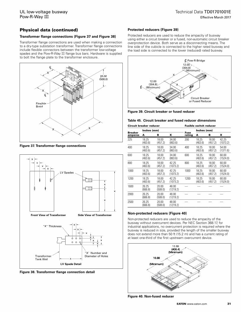
31
Technical Data TD01701001EEffective March 2017
UL low-voltage busway Pow-R-Way III
EATON www.eaton.com
Physical data (continued)Transformer flange connections (Figure 37 and Figure 38)
Transformer flange connections are used when making a connection to a dry-type substation transformer . Transformer flange connections include flexible connectors between the transformer low-voltage spades and the Pow-R-Way III flange bus bars . Hardware is supplied to bolt the flange plate to the transformer enclosure .
Figure 37. Transformer flange connections
Figure 38. Transformer flange connection detail
Protected reducers (Figure 39)
Protected reducers are used to reduce the ampacity of busway using either a circuit breaker or a fused, non-automatic circuit breaker overprotection device . Both serve as a disconnecting means . The line side of the cubicle is connected to the higher rated busway and the load side is connected to the lower (reduced) rated busway .
Figure 39. Circuit breaker or fused reducer
Table 45. Circuit breaker and fused reducer dimensions
Circuit breaker reducer Fusible switch reducer
Breaker amperes
Inches (mm) Fuse rating
Inches (mm)
A B X A B X
225 18.25 (463.6)
18.00 (457.2)
34.00 (863.6)
200 18.25 (463.6)
18.00 (457.2)
42.25 (1073.2)
400 18.25 (463.6)
18.00 (457.2)
34.00 (863.6)
400 18.25 (463.6)
18.00 (457.2)
54.00 (1371.6)
600 18.25 (463.6)
18.00 (457.2)
34.00 (863.6)
600 18.25 (463.6)
18.00 (457.2)
60.00 (1524.0)
800 18.25 (463.6)
18.00 (457.2)
42.25 (1073.2)
800 18.25 (463.6)
18.00 (457.2)
60.00 (1524.0)
1000 18.25 (463.6)
18.00 (457.2)
42.25 (1073.2)
1000 18.25 (463.6)
18.00 (457.2)
60.00 (1524.0)
1200 18.25 (463.6)
18.00 (457.2)
42.25 (1073.2)
1200 18.25 (463.6)
18.00 (457.2)
60.00 (1524.0)
1600 26.25 (666.8)
20.00 (508.0)
48.00 (1219.2)
— — — —
2000 26.25 (666.8)
20.00 (508.0)
48.00 (1219.2)
— — — —
2500 26.25 (666.8)
20.00 (508.0)
48.00 (1219.2)
— — — —
Non-protected reducers (Figure 40)
Non-protected reducers are used to reduce the ampacity of the busway without overcurrent devices . Per NEC Section 368 .17, for industrial applications, no overcurrent protection is required where the busway is reduced in size, provided the length of the smaller busway does not extend more than 50 ft (15 .2 m) and has a current rating of at least one-third of the first upstream overcurrent device .
Figure 40. Non-fused reducer
LLCLL
CLLCC
20.00(508.0)
FlexibleBraid
X
X
X X
x
xx
x
xx
xTransformerTank Wall
”X“ Number andDiameter of Holes
”X“ Thickness
LV Spade Detail
Front View of Transformer
LV Spades
xx
xx
x
x
x
Side View of Transformer
12.00(304.8)
(Minimum)
Pow-R-Bridge12.00
(304.8)(Minimum)
X
B
A
Circuit Breakeror Fused Reducer
C
C

32
Technical Data TD01701001EEffective March 2017
UL low-voltage busway Pow-R-Way III
EATON www.eaton.com
Physical data (continued)Meter center power takeoffs
Meter center power takeoffs (PTO) are designed to tap power off the busway and feed tenant meter stacks in high-rise applications . There are two types of power takeoffs, bridge joint and in-line . Both devices are UL Listed .
Bridge joint PTO
The bridge joint PTO shown in Figure 41 mounts to the right or left side of the busway at a joint between two sections of busway . The bridge joint PTO comes with a main circuit breaker or main fusible switch . Bridge joint PTOs should be ordered with the meter stacks through the Eaton Lincoln, IL, facility .
The height of the busway bridge joint must be coordinated to meet local utility/code requirements for minimum/maximum meter socket heights . All dimensions shown are for reference only showing a typical installation .
Figure 41. Bridge joint PTO
In-line PTO
The in-line PTO shown in Figure 42 is built integral with the busway, having the busway pass through the device . This space-saving design reduces the horizontal wall space by up to 24 .00 inches (609 .6 mm) . With this device, there is no need to install a separate main device; saving installation time and money . This device is available with a main circuit breaker, main fusible switch, or no main device . In-line PTOs should be ordered with the busway through the Eaton Greenwood, SC, facility .
The height of the first busway joint up through the floor must be coordinated to meet local utility/code requirements for minimum/maximum meter socket heights . The minimum distance from the surface on which the vertical hanger assembly will be installed on (finished floor or preformed curb) to the first joint is 16 .00 inches (406 .4 mm) . Meter stack may be placed to the left, right, or both sides of the main device . All dimensions shown are for reference only showing a typical installation .
otee:N If 5-high 200 A meter stacks are used, it is recommended to increase the bridge joint height from 20 .00 inches (508 .0 mm) to 22 .00– 24 .00 inches (558 .8–609 .6 mm) . Attention must be given to the minimum/maximum heights of the meter sockets .
Figure 42. In-line PTO
C
C
COFF
ON
12.26(311.4)
35.90(911.9)
38.76(984.5)
18.17(461.5)
20.00(508.0) 30.08
(764.0)
Horizontalcross bus
Bridgejoint
6.00(152.4)
Metercenterfront
70.00(1778.0)
18.00(457.2)
12.60(320.0)
12.40(314.9)
25.00(635.0)
VerticalBusway
8.48(215.4)
125 A meter stack
Wall
Floor
Wall
200 AStack
125 AStack
70.00(177.8)
67.34(1710.4)
Floor
12.45(316.2)
12.39(314.7)
30.88(784.35) 25.00
(635.0)
20.00(508.4)
20.00(508.4)
.50(12.7)
.61(15.5)
13.51(343.2)
1.93(49.0)
8.55 (217.2)12.26
(311.4)

33
Technical Data TD01701001EEffective March 2017
UL low-voltage busway Pow-R-Way III
EATON www.eaton.com
Physical data (continued)In-line power takeoff
Main circuit breaker PTO
The in-line main circuit breaker PTO shown in Figure 43 is available with trip ratings from 300 A to 1200 A; using L, M, and N frame circuit breakers . This device is indoor rated and may be weatherized upon request . See Table 46 for dimensions and ratings .
Main fusible switch PTO
The in-line main fusible switch PTO shown in Figure 44 is available with 400, 600, and 800 A switches; using Class “T” fuses . This device is indoor rated only . The switch handle is mounted in front, eliminating interference with the meter sockets and the need for spacers between the main device and meter stack . It comes with a hinged door, giving easy access to the fuses mounted below the main switch . See Table 46 for dimensions and ratings .
Unprotected PTO
The in-line PTO with no main device shown in Figure 45 comes with 1200 A horizontal cross bus as standard . This device is intended for use with six meter sockets or less or as local code permits . See Table 46 for dimensions and ratings .
Table 46. In-line PTO dimensions and ratings
DeviceShort-circuit rating (kAIC)
A dimensions in inches (mm)
Single bar per phase
Two bar per phase
Main circuit breakerLD 65 20.00 (508.0) 33.00 (838.2)HLD 100 20.00 (508.0) 33.00 (838.2)MDL 65 20.00 (508.0) 33.00 (838.2)HMDL 100 20.00 (508.0) 33.00 (838.2)ND 65 20.00 (508.0) 33.00 (838.2)HND 100 20.00 (508.0) 33.00 (838.2)Main fusible switch a
400 A 200 20.00 (508.0) 33.00 (838.2)600 A 200 20.00 (508.0) 33.00 (838.2)800 A 200 20.00 (508.0) 33.00 (838.2)No main device1200 A b 100 20.00 (508.0) 33.00 (838.2)
aClass “T” fuses only.bRating of horizontal cross bus.
Bridge Joint
12.00(304.8)
A
20.00(508.0)
30.00(762.0)
C
2.00(50.8)
Figure 43. Main breaker
Figure 44. Main fusible switch
Figure 45. Unprotected PTO
Bridge Joint
12.00(304.8)
A
20.00(508.0)
30.00(762.0)
C
5.00(127.0)
12.00(304.8)
A
15.00(381.0)
30.00(762.0)
Bridge JointCL

34
Technical Data TD01701001EEffective March 2017
UL low-voltage busway Pow-R-Way III
EATON www.eaton.com
Physical data (continued)Busway-connected panelboards
Pow-R-Way III busway-connected panelboards save space and installation time by eliminating the need to install a bus plug and cable over to a panelboard . This special enclosure plugs directly on to vertical busway and accepts Eaton PRL1a, PRL2a, and PRL3a main circuit breaker panelboard interiors . The enclosure also accepts 28 .00 inch (711 .2 mm) wide standard and EZ trims . The panels can be top or bottom fed and can mount on either side of the busway . Each panel is UL 857 Listed .
otee:N These panels are not seismic rated .
Busway-connected panelboards are sold and shipped through the Eaton regional satellite plants and coordinated with the Eaton busway plant in Greenwood, SC . See Figure 46 .
Panelboard spring hangers
The specialized spring hanger shown in Figure 47 allows the panel to be anchored and supported directly to a wall, and uniquely allows the panel to float with the riser busway . Panelboard spring hangers are sold separately as a busway accessory . Hardware is included to mount the spring hangers to the panelboard enclosure .
Table 47. Panelboard enclosure detail
MCB frame
Maximum box size MCB height
Busway joint height
Box height off floor
Minimum floor-ceiling height
Dimension in inches (mm)
A B C D
PRL1a and 2a main circuit breakerF 40.00 (1016.0) 72.00 (1828.8) 23.00 (584.2) 47.00 (1193.8) 103.00 (2616.2)F 52.00 (1320.8) 72.00 (1828.8) 23.00 (584.2) 35.00 (889.0) 103.00 (2616.2)F 64.00 (1625.6) 72.00 (1828.8) 23.00 (584.2) 23.00 (584.2) 103.00 (2616.2)J 76.00 (1930.4) 72.00 (1828.8) 33.00 (838.2) 21.00 (533.4) 113.00 (2870.2)K (500) 94.00 (2387.6) 74.00 (1879.6) 34.00 (863.6) 4.00 (101.6) 114.00 (2895.6)K (750) 94.00 (2387.6) 72.00 (1828.8) 36.00 (914.4) 6.00 (152.4) 116.00 (2946.4)PRL3a main circuit breakerF (4/0) 76.00 (1930.4) 72.00 (1828.8) 23.00 (584.2) 11.00 (279.4) 103.00 (2616.2)FCL 76.00 (1930.4) 72.00 (1828.8) 23.00 (584.2) 11.00 (279.4) 103.00 (2616.2)FB 76.00 (1930.4) 72.00 (1828.8) 23.00 (584.2) 11.00 (279.4) 103.00 (2616.2)J 76.00 (1930.4) 72.00 (1828.8) 23.00 (584.2) 11.00 (279.4) 103.00 (2616.2)K (500) 94.00 (2387.6) 74.00 (1879.6) 34.00 (863.6) 4.00 (101.6) 114.00 (2895.6)K (750) 94.00 (2387.6) 72.00 (1828.8) 36.00 (914.4) 6.00 (152.4) 116.00 (2946.4)L 94.00 (2387.6) 72.00 (1828.8) 34.00 (863.6) 4.00 (101.6) 114.00 (2895.6)LCL 94.00 (2387.6) 72.00 (1828.8) 38.00 (965.2) 8.00 (203.2) 118.00 (2997.2)LA 94.00 (2387.6) 72.00 (1828.8) 34.00 (863.6) 4.00 (101.6) 114.00 (2895.6)LG 94.00 (2387.6) 72.00 (1828.8) 36.00 (914.4) 6.00 (152.4) 116.00 (2946.4)
Edge of Busway to Wall
Top Conduit Space Top View
Third Plug-In OpeningUp From Lower Joint
A
B
C
Front View
2.37(60.2)
6.00(152.4)
28.00(711.2)
Figure 46. Busway-connected panelboard detail
Figure 47. Panelboard spring hangers

35
Technical Data TD01701001EEffective March 2017
UL low-voltage busway Pow-R-Way III
EATON www.eaton.com
Physical data (continued)Pow-R-Way III adapters (Figure 48 and Figure 49)
A complete line of adapters are available to enable the user to add to existing old-line Westinghouse or obsolete Eaton’s bus runs with the Pow-R-Way III design . The specific Westinghouse product lines are Low Impedance Busway, Current Limiting Busway, Pow-R-Way, and Pow-R-Way II . The obsolete Cutler-Hammer® designs are CP2, CP3, and CP4 Safetybus . See Table 48 .
The adapters allow the incorporation of present day technologies, available in Pow-R-Way III plug-in units, into existing busway systems . State-of-the-art features such as energy monitoring, transient voltage surge suppression, and coordination/communication capabilities can all be added to existing distribution systems without having to upgrade and to replace entire runs of busway . See Table 48 .
Special adapters to competitive busway products are also available . Please contact the Greenwood factory for information .
Table 48. Available Pow-R-Way III adapters
Busway types BrandMinimum adapter length in inches (mm)
Low impedance busway Westinghouse 60.00 (1524.0)Low impedance plug-in busway
Westinghouse 60.00 (1524.0)
Pow-R-Way busway (225 to 1600 A)
Westinghouse/Eaton 31.37 (796.8)
Pow-R-Way busway (2000 to 5000 A)
Westinghouse/Eaton 33.88 (860.6)
Pow-R-Way II busway Westinghouse/Eaton 36.00 (914.4)
CP2 Safetybus Eaton 36.00 (914.4)CP3 Safetybus Eaton 36.00 (914.4)CP4 Safetybus Eaton 36.00 (914.4)Competitive busway Contact factory 36.00 (914.4)
otee:N Please contact product line regarding variation from standard dimension offerings .
Figure 48. Pow-R-Way III to Pow-R-Way adapter
Figure 49. Pow-R-Way III to CP adapter
POW–R–WAY III ExistingPOW–R–WAY
Adapter
POW–R–WAY III ExistingCP Busway
Adapter

36
Technical Data TD01701001EEffective March 2017
UL low-voltage busway Pow-R-Way III
EATON www.eaton.com
Physical data (continued)Wall/floor flanges (Figure 50)
Wall and floor flanges are used to fit around the busway and close off the opening made to allow the bus run to pass through a floor or wall . Wall and floor flanges are for cosmetic purposes only and do not provide any type of vapor or fire barrier .
Roof flange (Figure 51)
A roof flange should always be used when outdoor busway penetrates a roof .
End closures (Figure 52)
End closures terminate a bus run and can be used to close either the right or left end (see Figure 2 on page 2 for wiring conductor configurations) .
Table 49. End closures
UL 857 ampere rating Dimensions in Inches (mm)
Cu Al A
225 225 5.13 (130.3)400 400 5.13 (130.3)600 600 5.13 (130.3)800 — 5.13 (130.3)1000 — 5.75 (146.1)1200 800 6.25 (158.8)1350 1000 6.75 (171.5)1600 1200 7.77 (197.4)2000 1350 9.02 (229.1)— 1600 9.78 (248.4)2500 2000 11.55 (293.4)3200 — 16.52 (419.6)4000 2500 19.02 (482.9)— 3200 20.54 (521.7)5000 4000 24.08 (611.6)
Table 50. End closure dimensions
Description
Dimensions in inches (mm)
B
3WH, 3WG, 3WHG, 3WI, 4WH, 4WG, 4WHG, 4WI 5.00 (127.0)4WNH, 4WNG, 4WNI, 4WNHG 5.50 (139.7)
otee:N End closure extends 0 .44 inches (11 .2 m) rating beyond the centerline of the removed Pow-R-Bridge .
BuswayWidth
BuswayHeight
Wall
Wall/FloorFlange
2.00(50.8)
2.00(50.8)
Figure 50. Wall/floor flange
Figure 51. Roof flange
Figure 52. End closure with Pow-R-Bridge removed
Bell
Flange
Roof Flange
Roof
Maximum Roof Slope with Standard Flange is 2.00 (50.8) per ft(304.8 mm)
2.50(63.5) (All 4 Sides)
of JointCL10.25 (minimum)
(260.3)
7.00 (177.8)
2.00 (Rec.)(50.8)
CL
6.25 (158.8)Indoor
7.38 (187.5)Outdoor
A
B
.44 (11.2)
CL

37
Technical Data TD01701001EEffective March 2017
UL low-voltage busway Pow-R-Way III
EATON www.eaton.com
Physical data (continued)Horizontal hangers
One hanger is provided for every 10 ft (3 m) of horizontally mounted busway . The type of hanger supplied is determined by the specific mounting requirements of the busway . (For hook hangers and angle hangers, see Figure 53 and Figure 54 .)
Drop rods 0 .50 inch (12 .7 mm) diameter are not included and must be furnished by the installer . Drop rods 0 .75 inch (19 .1 mm) diameter are required for seismic applications .
1 Bar Per Phase Only
Flatwise Edgewise
DuctWidth
DuctWidth
DuctHeight
A
C
B
Figure 53. Hook hangers—non-seismic only
Table 51. Flatwise hook hanger
UL 857 ampere rating Dimensions in inches (mm)
Cu Al Duct width A B C
225 225 4.75 (120.7) 5.12 (130.0) — —400 400 4.75 (120.7) 5.12 (130.0) — —600 600 4.75 (120.7) 5.12 (130.0) — —800 — 4.75 (120.7) 5.12 (130.0) — —1000 — 5.38 (136.7) 5.75 (146.1) — —1200 800 5.88 (149.4) 6.25 (158.8) — —1350 1000 6.38 (162.1) 6.75 (171.5) — —1600 1200 7.38 (187.5) 7.75 (196.9) — —2000 1350 8.64 (219.5) 9.03 (229.4) — —— 1600 9.40 (238.8) 9.78 (248.4) — —2500 2000 11.17 (283.7) 11.58 (294.1) — —
Table 52. Edgewise hook hanger
Conductor configuration
Dimensions in inches (mm)
Duct height Duct width B C
3WH/4WH/3WG/3WHG/4WG/4WHG 4.38–4.56 (111.2–115.8) 4.75–6.38 (120.7–162.1) 8.40 (213.3) 4.81 (122.2)3WI/4WI 4.38–4.56 (111.2–115.8) 7.38–11.17 (187.4–283.7) 13.19 (335.0) 4.81 (122.2)4WNH/4WNG 4.92–5.10 (125.0–129.5) 4.75–6.38 (120.7–162.1) 8.40 (213.3) 5.35 (135.9)4WNHG/4WNI 4.92–5.10 (125.0–129.5) 7.38–11.17 (187.4–283.7) 13.19 (335.0) 5.35 (135.9)
Table 53. Flatwise angle hanger
UL 857 ampere rating Conductor bars per phase
Dimensions in inches (mm)
Busway width ACu Al
225 225 1 4.75 (120.7) 9.00 (228.6)400 400 1 4.75 (120.7) 9.00 (228.6)600 600 1 4.75 (120.7) 9.00 (228.6)800 — 1 4.75 (120.7) 9.00 (228.6)1000 — 1 5.38 (136.7) 9.63 (244.6)1200 800 1 5.88 (149.4) 10.12 (257.0)1350 1000 1 6.38 (162.1) 10.63 (270.0)1600 1200 1 7.38 (187.5) 11.63 (295.4)2000 1350 1 8.64 (219.5) 12.88 (327.2)— 1600 1 9.40 (238.8) 13.62 (345.9)2500 2000 1 11.17 (283.7) 15.44 (392.2)3200 — 2 16.14 (410.0) 20.39 (517.9)4000 2500 2 18.64 (473.5) 22.88 (581.2)— 3200 2 20.16 (512.1) 24.39 (619.5)5000 4000 2 23.70 (602.0) 28.00 (711.2)
Table 54. Edgewise angle hanger
Conductor configuration
Dimensions in inches (mm)
Duct height A
3WH/4WH/3WG/3WHG/4WG/4WHG/3WI/4WI
4.38–4.56 (111.2–115.8) 9.00 (228.6)
4WNH/4WNG/4WNHG/4WNI 4.92–5.10 (125.0–129.5) 9.36 (237.7)
otee:N Angle hangers must be used for seismic applications .
Figure 54. Angle hangers
Flatwise
.7(19
A
.75 75 Edgewise
2 Bars Per PhaseA
.75
1 Bar Per PhaseA
.75

38
Technical Data TD01701001EEffective March 2017
UL low-voltage busway Pow-R-Way III
EATON www.eaton.com
Physical data (continued)
Figure 55. Sway brace
Sway brace
Sway brace brackets provide a provision to brace the busway run at a 45-degree angle, restricting the suspended busway from swinging . Sway braces can be ordered as part number BVC1102G01 regardless of height of busway dimension “A” .
Vertical hangers (Figure 56 and Figure 57)
When busway is to be installed vertically, a spring suspension type vertical hanger should be used . Vertical hangers are not provided unless specified .
This unique hanger equalizes the weight of vertically mounted busway along all supports . A vertical hanger must be used on each floor and at the end of the bus run on the last floor .
The maximum span permitted by UL on vertical hangers is 16 ft (4 .9 m) . Intermediate hangers are required for floor heights exceeding 16 ft (4 .9 m) .
Table 55. Edgewise vertical hangers (F and F-opposite sides)
Conductor configuration
Busway Height
Hangers on “F” and “F” Opposite Sides
Inches (mm) A inches (mm)Figure 57 configuration
3WH/4WH 4.38 (111.3) 4.72 (119.9) A3WG/3WHG/4WG/4WHG 4.50 (114.3) 4.91 (124.7) A3WI/4WI 4.56 (115.8) 4.91 (124.7) A4WHN 4.92 (125.0) 5.25 (133.4) A4WNG/4WNHG 5.05 (128.3) 5.44 (138.2) A
Figure 56. Typical installation
Table 56. Flatwise vertical hangers (T and T-opposite sides)
UL 857 ampere rating Busway width
Hangers on “T” and “T” opposite sides
Cu Al Inches (mm) A inches (mm)Figure 57 configuration
225 225 4.75 (120.7) 4.62 (117.3) B400 400 4.75 (120.7) 4.62 (117.3) B600 600 4.75 (120.7) 4.62 (117.3) B800 — 4.75 (120.7) 4.62 (117.3) B1000 — 5.38 (136.7) 5.25 (133.4) B1200 800 5.88 (149.4) 5.75 (146.1) B1350 1000 6.38 (162.1) 6.25 (158.8) B1600 1200 7.38 (187.5) 7.25 (184.2) B2000 1350 8.64 (219.5) 8.50 (215.9) B— 1600 9.40 (238.8) 9.25 (235.0) C2500 2000 11.17 (283.7) 11.06 (280.9) C3200 — 16.14 (410.0) 16.00 (406.4) D4000 2500 18.64 (473.5) 18.50 (469.9) D— 3200 20.16 (512.1) 20.06 (510.0) D5000 4000 23.70 (602.0) 23.59 (600.0) D
Figure 57. Vertical hangers
A
Edgewise(1 Bar per Phase)
Flatwise(1 Bar per Phase)
Flatwise(2 Bar per Phase)
Configuration A(1 Bar per Phase)
Configuration B(1 Bar per Phase)
A
A A
Configuration C(1 Bar per Phase)
Configuration D(2 Bar per Phase)
A

39
Technical Data TD01701001EEffective March 2017
UL low-voltage busway Pow-R-Way III
EATON www.eaton.com
Plug-in protective devicesAll Pow-R-Way III plug-in units are designed with the safety of the installer and user as the key criteria . The following features are standard for both fusible and circuit breaker type plug-in units:
Pow-R-Way III bus plugs have extended ground and neutral bars, which bring the termination points down into the cable entry area making for a safer, easier connection .
A barrier is provided over the line side connections from the bus plug stab assembly to the fusible switch or circuit breaker .
The bus plug ground stab makes positive contact with the busway ground (integral or internal) before the phase or neutral stabs contact the bus bars .
A bus plug guide port is provided in the busway housing, to the right of each plug-in outlet . A polarizing alignment pin is located at the line side end of each bus plug enclosure . The alignment pin must be inserted into the guide port for proper installation . The plug-in unit and the busway are interlocked to ensure that the device is in the OFF position prior to installation or removal of the unit .
To ensure that the bus plug is seated onto the busway, the clamping mechanism will draw the unit tight onto the busway housing as the installer tightens the clamps .
Plug-in units have an interference bracket that prevents the cover from being opened while the device is in the ON position and to prevent accidental closing of the device while the cover is open .
There are two locations available for field positioning of the bus plug operating handle for all circuit breaker bus plugs and fusible plugs over 400 A and higher . On vertical bus run applications, the handle can be mounted on the side of the plug, and for horizontal runs, the handle can be mounted on the (line side) end of the unit . Bus plugs are shipped with the handle mounted on the end as standard . Mounting positions are illustrated in Figure 60 .
When a plug-in unit is installed, the bus plug stab base assembly engages a seating ridge provided on the plug-in outlet . The stab base is drawn in to overlap the ridge and to form a tight seal against moisture and dust .
Figure 58. Plug-in stab details
Figure 59. Plug-in outlet details
Plug-in device mounting
The load end of a plug-in unit varies with the orientation of the busway as determined by the “F” and “T” markings (see Figure 60 below) .
Figure 60. Plug-in device mounting
OF
OFO
NO
F
DA
NG
Guide Pinand Port
Clamp and Guide
OFF
ON
Finger-SafeBarriersT
F
Ground StabGuide Port
Outlet Seating Ridge Mounting Hardware
ON
OFF
Handle
Load
Load
Handle
ON
OFF
LoadHandle
ON
OFF
Load
HandleON
OFF
ON
OFF
Load
Handle
ON
OFF
ON
OFF
ON
OFF
Load
Load
Load
Handle
HandleHandle
TFTF
TTFF
T
FF

40
Technical Data TD01701001EEffective March 2017
UL low-voltage busway Pow-R-Way III
EATON www.eaton.com
Plug-in device mounting (continued)
Plug-in openings are spaced every 24 .00 inches (609 .9 mm) starting 12 .00 inches (304 .8 mm) in from the centerline of each bridge joint with a maximum of five openings per side of an individual section of busway . Figure 61 and Figure 62 illustrate the number of plug-in openings taken up by each style/size bus plug .
Figure 61. Fusible plug-in device mounting
Each plug-in unit uses only one plug-in opening; however, may cover up additional plug-in openings preventing use .
Figure 62. Breaker plug-in device mounting
44.19"
P3F325 (400 A), P3F365 (400 A),P33F236 (600 A), P3F366 (600 A),P3F327 (800 A) and P3F367 (800 A)(Occupies 3 Plug-in Openings)
17.00 Min.12.00"24.00"24.00"24.00"24.00"12.00"
8.00" Min.
18.12"
of Opening
End of Clamp 19.00"20.75"
Can't Use
P3F321(30 A), P3F361 (30 A), P33F361H (30 A), P3F322 (60 A),P3F362 (60 A), P3F362H (60 A)P3F323(100 A), P3F363(100 A) and P3F363H (100 A) (Occupies 1 Plug-in Opening)
P3F364H (200 A) and P3F365H (400 A)(Occupies 1 Plug-in Opening)
P3F324 (200 A) and P3F364 (200 A)(Occupies 2 Plug-in Openings)
10 ft. SectionShown
T F
FT
Can't Use
of Opening
End of Clamp
of Opening
CL
CL
CL
End of Clamp
of Opening
CL
End of Clamp
41.31"
P3B2D, P3BMD, P3BND and P3BLAP(Occupies 2 Plug-in Openings)
17.00 MIN.12.00"24.00"
24.00"24.00"24.00"12.00"
8.00" MIN.
16.50"
18.62"29.75"
P3BFD(Occupies 1 Plug-in Opening)
P3BJD(Occupies 1 Plug-in Opening)P3BKD(Occupies 2 Plug-in Openings)
37.25"
P3BLCL(Occupies 2 Plug-in Openings)
"T" F
"T" F
of Opening
CL
of Opening
CL of Opening
CL
End of Clamp
End of Clamp
End of Clamp
10 ft. SectionShown
of Opening
CL
of Opening
CL
End of Clamp
End of Clamp
Can't Use

41
Technical Data TD01701001EEffective March 2017
UL low-voltage busway Pow-R-Way III
EATON www.eaton.com
SPD plug-in devicesSPD Series (Figure 63)
The Pow-R-Way III plug-in device product offering includes a surge protective device (SPD), which is ideal for busway fed distribution systems . A transient voltage is a random, high energy, short duration electrical anomaly . These high energy surges can disrupt, damage, or destroy sensitive microprocessor-based equipment . Eaton has developed the SPD family of products to ensure that quality power is supplied to commercial, industrial, medical, and institutional facilities .
The SPD not only protects against externally created impulse transients such as lightning, utility capacitor switching, and disturbances emitted by adjacent facilities, but it also provides needed protection against internal transients . This type of transient is generated within a facility’s own distribution system . Sources of internally generated, or ringwave, transients are imaging, equipment, variable frequency drives, lighting dimmers, arc welders, and the switching on and off of electrical distribution equipment . It is estimated that over 80% of surge disturbances are actually caused by internal transients .
The SPD also filters repetitive electrical line noise (EMI/RFI), which is defined as any unwanted electrical signal that produces undesirable effects in the circuits of sensitive electronic equipment or disturbances that are two times peak voltage . The suppression of AC transients is accomplished through the use of metal oxide varistors (MOVs) that provide a low impedance path to divert surges away from loads . Electrical line noise and ringing transients are eliminated by adding filtering capacitors to the suppression device .
Not all SPD units on the market have filtering capabilities . The benefits of combining SPD and filtering are reduced MOV stress, resulting in a longer life cycle, lower let-through voltage, better noise attenuation levels, and increased reliability .
Without protection devices, electronic-based loads and microprocessors are not provided with the noise- and disturbance-free power that they require . Because microprocessors are now common in those facilities, specifiers must ensure that the AC power supply is properly filtered . Significant performance advantages are achieved by integrating SPD filters into busway systems .
Because the SPD unit is directly connected to the busway it is able to minimize let-through voltage and to isolate critical loads that are fed from a protected busway run . Due to the integrated design, the SPD bus plug saves the user-needed wall space and greatly reduces the installed project cost . The SPD bus plug is furnished with a breaker disconnect . For catalog numbers and selection criteria, see Table 57 below .
Figure 63. Surge protective device (SPD Series) bus plug
Table 57. SPD bus plugs catalog numbering system
otee:N Available for Pow-R-Way III plugs . This information is required for all quotations . This information should also be included at order entry to ensure prompt processing of the order .
P3BSPD 250 480Y 2 C
Fixed—do not change
Surge rating (kA/phase)
5080100120160
200250300400
Diagnostics package
1 = Basic—Dual-colored LED per phase to indicate protection status of the N–G mode on units with a neutral wire, single-colored LED to indicate the lack of a neutral wire connection on systems with a neutral wire.2 = Standard—Dual-colored LED per phase to indicate protection status of the N–G mode on units with a neutral wire, single-colored LED to indicate the lack of a neutral wire connection on systems with a neutral wire, audible alarm with silence button, and Form C relay contact.3 = Standard + surge counter—Dual-colored LED per phase to indicate protection status of the N–G mode on units with a neutral wire, single-colored LED to indicate the lack of a neutral wire connection on systems with a neutral wire, audible alarm with silence button, Form C relay contact, EMI/RFI filtering providing up to 50 dB of noise attenuation from 10 kHz to 100 MHz, and surge counter with reset button.
Fixed—do not change
Voltage code
208Y = 208Y/120 V (4W + G)400Y = 400Y/230 V (4W + G)480Y = 480Y/277 V (4W + G)600Y = 600Y/347 V (4W + G)240D = 240 delta (3W + G)480D = 480 delta (3W + G)600D = 600 delta (4W + G)

42
Technical Data TD01701001EEffective March 2017
UL low-voltage busway Pow-R-Way III
EATON www.eaton.com
Plug-in devices (continued)Ground detector/neutralizer bus plug (Figure 64)
In rare cases, bus bars in a busway system pick up static electricity . In order to discharge this potential, a neutralizer and ground detector bus plug is available . The unit has three 18,000 ohm resistors connected between the bus bars and the ground . Static electricity is discharged through these resistors . A neon lamp is wired in series with the bus bar and part of the resistor and burns continuously . If there is a ground anywhere on the system of a lower resistance than the path through the lamp, the lamp will go out, indicating that there is a short in the system .
Figure 64. Ground detector/neutralizer bus plug
Combination starter bus plugs (see Figure 65)
Eaton Freedom™ and Advantage™ motor starters are included in the Pow-R-Way III bus plug product offering . Freedom motor starters offer state-of-the-art features that ensure greater value, flexibility, and performance in the toughest commercial and industrial applications .
Advantage motor starters have features including a solid-state, heaterless overload relay with built-in ground fault protection . Advantage also features communication capabilities and an on- board microprocessor that controls the contactor magnet to eliminate burnout in low-voltage or varying control circuit conditions .
Plug-in combination starters or contactors are mounted in enclosures identical to the circuit breaker and fusible switch type bus plugs including the clamp and guides, safety interlocks, and guide pin . They are available from size 0 through 5 with a circuit breaker, motor circuit protector, or fusible disconnect . Contact Eaton for specific application and outline dimensions .
Figure 65. Freedom/Advantage bus plug
Cover(Cutaway)18,000 Ohm
Resistors (3) GroundIndicatingLamp (3)
GroundConnection
AdvantageStarter

43
Technical Data TD01701001EEffective March 2017
UL low-voltage busway Pow-R-Way III
EATON www.eaton.com
Plug-in devices (continued)Digitrip OPTIM bus plugs (Figure 66)
Digitrip OPTIM™ is a programmable, communicating, micro-processor-based electronic trip unit system for Eaton Series C circuit breakers . OPTIM is available for Pow-R-Way III bus plugs on K-Frame (125–400 A), L-Frame (70–600 A), and N-Frame (400–1200 A) circuit breakers . Digitrip OPTIM provides an electrical distribution system with superior programmable protection, coordination, and a state-of-the-art advanced warning capability along with system diagnostics, monitoring, and communications . Digitrip OPTIM is available in two trip unit types: OPTIM 550 and OPTIM 1050 .
Unique Digitrip OPTIM features can provide time current settings with more increments that permit the user to OPTIMize system protection and coordination; improved accuracy to give more selectivity and closer sensitivity in providing coordination; programmable short delay and/or instantaneous curve tripping options; and selectable thermal memory, as well as selectable sure start discriminator protection features . Increased system security is provided by the addition of a programmable password protection . For improved system coordination, I4t long delay time slope has been added to the traditional nine LSIG curve shaping options . Short delay and ground delay zone selective interlocking have also been added, down to a 70 A circuit breaker .
The following Advance Warning options are also available: • A programmable high load phase and neutral alarm, adjustable
between 50% and 100% of Ir (LDPU setting), will signal an impending trip condition
• An adjustable ground fault alarm that will alert the user of a ground fault condition without the breaker
• Energy alarming can be performed (such as peak demand exceeded) to reduce energy costs with OPTIM 1050 via PowerNet
• Total Harmonic Distortion (THD) alarming detects changes in power quality with OPTIM 1050 via PowerNet
Digitrip OPTIM provides a complete selection of system diagnostic capabilities including four cause-of-trip LEDs mounted on the front of the trip unit to improve troubleshooting capabilities . They are complemented by trip event information that is stored in memory after a trip condition . Remote breaker status indication is provided by auxiliary and alarm switches . The Breaker Interface Module (BIM) provides trip indication information on the front of the unit or via relay contacts to a remote location .
Digitrip OPTIM has an extensive menu of monitoring capabilities including load monitoring, power factor (OPTIM 1050), power and energy (OPTIM 1050) power quality-current harmonics .
OPTIM trip units are PowerNet compatible and can be included in the unique Eaton tripping PowerNet communications system . Contact Eaton for specific applications and outline dimensions .
Figure 66. OPTIM bus plug
Figure 67. Bus plugs
Table 58. OPTIM breaker plug-in unit dimensions
OPTIM breakerframe
Maximumamperes
Maximum Vac
Dimensions in inches (mm) Mechanical terminal
A B C D E FWire range per phase
Approx. weight lb (kg)
K-Frame 400 600 34.40 (873.8)
19.30(490.2)
11.46(291.1)
12.42(315.5)
3.77(95.8)
7.86(199.6)
350 A (1) 250–500 kcmil 400 A (2) 3/0–250 kcmil
59 (26.8)
L-Frame 600 600 41.90 (1064.3)
24.44(620.8)
11.46(291.1)
13.85(351.8)
3.77(95.8)
9.57(243.1)
400 A (1) 4/0–600 kcmil 400 A (2) 400–500 kcmil
78 (35.4)
N-Frame 800 600 45.89 (1165.6)
29.65(753.1)
11.46(291.1)
17.46(443.5)
3.77(95.8)
9.66(345.4)
700 A (2) 1–500 kcmil 800 A (3) 3/0–400 kcmil
141 (64.0)
Plug-in Opening and B
Plug-In Opening
Handle CLCL
CLED
F
ON
OFFA B
C

44
Technical Data TD01701001EEffective March 2017
UL low-voltage busway Pow-R-Way III
EATON www.eaton.com
Power takeoff sections Power takeoff sections are used to tap up to 1200 A of power off of the busway . A power takeoff section must be used when power in excess of the current-carrying capabilities of the plug-in stabs (800 A) is required . A bolt-on fusible switch or circuit breaker unit can then be bolted to the power takeoff .
Bridge joint power takeoff (Figure 68)
A bridge joint power takeoff is a special connection that allows for the attachment of a bolt-on unit at the bridge joint . The bridge joint power takeoff and a bolt-on unit can be used to tap off power where plug-in busway is not available . A bridge joint power takeoff can be rated up to 1000 A .
Figure 68. Bridge power takeoff
Built-in power takeoff (Figure 69)
A built-in power takeoff is a special piece of feeder busway that allows for the attachment of a bolt-on unit . Built-in power takeoffs are used where space restrictions dictate that the wide dimensions of the busway be flat against the wall, ceiling, or other obstruction . In this application, power takeoffs and bolt-on units are used instead of plug-in units . A built-in power takeoff can be rated up to 1200 A .
Figure 69. Built-in power takeoff
Plug-in cable tap boxes (Figure 70)
Plug-in cable tap boxes are used to feed the busway run, or where equipment served by the busway is connected without overcurrent protection . Plug-in cable tap boxes plug into any Pow-R-Way III busway (225–5000 A) plug in opening .
Figure 70. Plug-in cable tap box
Table 59. Plug-In cable tap box details
Ampere rating
Dimensions in inches (mm)Compression conn./Phase and N Mechanical lugs/phase and N
Catalog numberA B C D English Metric English Metric
200 19.50 (495.3) 15.50 (393.7) 7.12 (180.8) 7.50 (190.5) (1) (1) — — P3PTB200C200 19.50 (495.3) 15.50 (393.7) 7.12 (180.8) 7.50 (190.5) — — (1) #4–350 kcmil (1) 21.2–177 mm2 P3PTB200M400 26.25 (666.7) 21.00 (533.4) 10.00 (254.0) 7.50 (190.5) (1) (1) — — P3PTB400C400 26.25 (666.7) 21.00 (533.4) 10.00 (254.0) 7.50 (190.5) — — (1) 250–750 kcmil or
(2) 3/0–250 kcmil(1) 127–380 mm2 or (2) 85.0–127 mm2
P3PTB400M
600 30.00 (762.0) 24.75 (628.6) 10.50 (266.7) 12.80 (325.1) (2) (2) — — P3PTB600C600 30.00 (762.0) 24.75 (628.6) 10.50 (266.7) 12.80 (325.1) — — (2) 250–750 kcmil or
(4) 3/0–250 kcmil(1) 127–380 mm2 or (4) 85.0–127 mm2
P3PTB600M
800 30.00 (762.0) 24.75 (628.6) 10.50 (266.7) 12.80 (325.1) (3) (3) — — P3PTB800C800 30.00 (762.0) 24.75 (628.6) 10.50 (266.7) 12.80 (325.1) — — (3) 250–750 kcmil or
(6) 3/0–250 kcmil(3) 127–380 mm2 or (6) 85.0–127 mm2
P3PTB800M
Load
Line
DANGER
DANGER
F
P.T.O.
Bolt-on Circuit Breaker Unit or Fusible Switch
Pow-R-BridgeCL
17.00(431.8)
(Minimum)
6.94(176.3)
9.00(228.6)
15.00(381.0)
17.00(431.8)
(Minimum)
15.00(381.0)
6.94(176.3)
9.00(228.6)
Pow-R-Bridge Pow-R-Bridge
P.T.O.
Edgewise MountedSingle Bar Per Phase Only
Flatwise MountedAvailable in Single and Double Bars Per Phase
P.T.O.CL
FT
CLCL
CL
A
B
CD
Top View
Side View

45
Technical Data TD01701001EEffective March 2017
UL low-voltage busway Pow-R-Way III
EATON www.eaton.com
Receptacle plug-in unitsEaton’s unique receptacle plug-in unit design makes them the most flexible receptacle units in the industry . Pow-R-Way III receptacle plug-in units come fully assembled and wired, reducing installation time, and are built to order . They are CSA® and UL 857 Listed and come in five different configurations .
Single receptacle unit
The single receptacle plug-in unit, shown in Figure 71, is configured to order and uses Type FD single-pole or two-pole plug-in circuit breakers . One receptacle comes with each unit that can be straight blade or twist-lock, rated from 15 to 50 A . Each receptacle can also be fixed mounted to the front of the enclosure or cord mounted from the bottom of the enclosure (not as shown) . Cord lengths are 1–15 ft in 1-ft increments . Consult NEC Sections 368, 400, and 645 for cord drop applications .
Quad receptacle unit
The quad receptacle plug-in unit, shown in Figure 72, is configured to order and uses Type FD single-pole, two-pole, and three-pole plug-in circuit breakers . Each unit comes with 2–4 NEMA configured receptacles in any combination of straight blade and twist-lock and three-wire, four-wire, and five-wire, rated 15–50 A . Each receptacle is cord mounted from the bottom of the enclosure . Cord lengths are 1–15 ft in 1-ft increments . Consult NEC Sections 368, 400, and 645 for cord drop applications .
Figure 71. Single receptacle plug
Figure 72. Quad receptacle plug
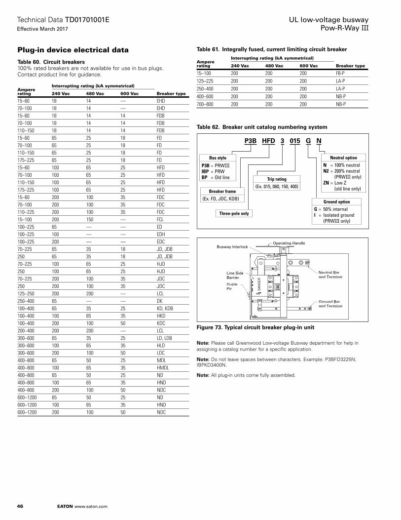
46
Technical Data TD01701001EEffective March 2017
UL low-voltage busway Pow-R-Way III
EATON www.eaton.com
Plug-in device electrical data
Table 60. Circuit breakers100% rated breakers are not available for use in bus plugs . Contact product line for guidance .
Ampere rating
Interrupting rating (kA symmetrical)
Breaker type240 Vac 480 Vac 600 Vac
15–60 18 14 — EHD70–100 18 14 — EHD15–60 18 14 14 FDB70–100 18 14 14 FDB110–150 18 14 14 FDB15–60 65 25 18 FD70–100 65 25 18 FD110–150 65 25 18 FD175–225 65 25 18 FD15–60 100 65 25 HFD70–100 100 65 25 HFD110–150 100 65 25 HFD175–225 100 65 25 HFD15–60 200 100 35 FDC70–100 200 100 35 FDC110–225 200 100 35 FDC15–100 200 150 — FCL100–225 65 — — ED100–225 100 — — EDH100–225 200 — — EDC70–225 65 35 18 JD, JDB250 65 35 18 JD, JDB70–225 100 65 25 HJD250 100 65 25 HJD70–225 200 100 35 JDC250 200 100 35 JDC125–250 200 200 — LCL250–400 65 — — DK100–400 65 35 25 KD, KDB100–400 100 65 35 HKD100–400 200 100 50 KDC200–400 200 200 — LCL300–600 65 35 25 LD, LDB300–600 100 65 35 HLD300–600 200 100 50 LDC400–800 65 50 25 MDL400–800 100 65 35 HMDL400–800 65 50 25 ND400–800 100 65 35 HND400–800 200 100 50 NDC600–1200 65 50 25 ND600–1200 100 65 35 HND600–1200 200 100 50 NDC
Table 61. Integrally fused, current limiting circuit breaker
Ampere rating
Interrupting rating (kA symmetrical)
Breaker type240 Vac 480 Vac 600 Vac
15–100 200 200 200 FB-P125–225 200 200 200 LA-P250–400 200 200 200 LA-P400–600 200 200 200 NB-P700–800 200 200 200 NB-P
Table 62. Breaker unit catalog numbering system
Figure 73. Typical circuit breaker plug-in unit
otee:N Please call Greenwood Low-voltage Busway department for help in assigning a catalog number for a specific application .
otee:N Do not leave spaces between characters . Example: P3BFD3225N; IBPKD3400N .
otee:N All plug-in units come fully assembled .
P3B HFD 3 015 G N
Bus style
P3B = PRWIIIIBP = PRWBP = Old line
Breaker frame
(Ex. FD, JDC, KDB)
Three-pole only
Trip rating
(Ex. 015, 060, 150, 400)
Ground option
G = 50% internalI = Isolated ground (PRWIII only)
Neutral option
N = 100% neutralN2 = 200% neutral (PRWIII only)ZN = Low Z (old line only)
Busway InterlockOperating Handle
Line SideBarrier
GuidePin
Neutral Barand Terminal
Ground Barand Terminal

47
Technical Data TD01701001EEffective March 2017
UL low-voltage busway Pow-R-Way III
EATON www.eaton.com
Plug-in device electrical data (continued)
Table 63. Fusible switch horsepower and short-circuit rating (based on fuse class)
Ampere rating NEC standard Maximum
Maximum symmetrical rms at fuse class
240 V30 3 7.5 200 kA–R60 7.5 15 200 kA–R100 15 30 200 kA–R200 25 60 200 kA–R400 50 125 200 kA–R600 75 200 200 kA–R800 100 250 200 kA–L480 V30 5 15 200 kA–R60 15 30 200 kA–R100 25 60 200 kA–R200 50 125 200 kA–R400 100 250 200 kA–R600 150 400 200 kA–J800 200 500 200 kA–L600 V30 7.5 20 200 kA–R60 15 50 200 kA–R100 30 75 200 kA–R200 60 150 200 kA–R400 125 350 200 kA–J600 200 500 200 kA–J800 250 500 200 kA–L
Figure 74. Vertically mounted plug
Figure 75. Horizontally mounted plug
Table 64. Fusible unit catalog numbering system
otee:N Mounting option prefix used on 30 A, 60 A, 100 A, and 200 A plug-in units only .
Figure 76. Typical fusible plug-in unit
otee:N “H” clips are standard for ITAP and TAP unless specified by adding “R” in catalog number . “R” clips are standard for P3F .
otee:N Please call Greenwood Low-voltage Busway department for help in assigning a catalog number for a specific application .
otee:N Do not leave spaces between characters . Example: P3F362RNV; ITAP361N .
otee:N All plug-in units come fully assembled .
Mounting options for P3F
(30–200 A only)
H = HorizontalV = Vertical
P3F 3 6 4 R G N H
Bus style
P3F = PRWIIIITAP = PRWTAP = Old line
Three-pole only
Voltage
6 = 600 V2 = 240 V
Amperes
1 = 302 = 603 = 1004 = 2005 = 4006 = 6007 = 800
Fuse clips
H, J, or R ≤ 600 A T or L for 800 A
Ground option
G = 50%I = Isolated (PRWIII only)
Neutral options
N = 100%N2 = 200% (PRWIII only)ZN = Low Z (old line only)
Ground Bar& Terminal
GuidePin
Operating HandleBuswayInterlock
Neutral Bar& Terminal

48
Technical Data TD01701001EEffective March 2017
UL low-voltage busway Pow-R-Way III
EATON www.eaton.com
Plug-in device physical data
Figure 77. Bus plugs
Table 65. Standard plug-in units
Plug-in unit
Max. A
Max. Vac
Dimensions in inches (mm) Standard mechanical terminal abApprox. weight lb (kg)A B C D E F
Wire range per phase (mm2)
Ground wire range
100% neutral wire range
Circuit breaker plug-in units cP3BFD (E- and F-frame breakers)
225 600 21.20 (538.5)
12.36 (314.0)
5.43 (138.0)
4.00 (101.6)
6.25 (158.8)
6.06 (153.7)
15–100 A (1) #14–1/0 (2.5–50) 110–225 A (1) #4–4/0 (25–95)
15–125 A #14–1/0150–225 A 1/0–4/0
15–125 A #14–1/0150–225 A 1/0–4/0
25 (11.3)
P3BJD (J-frame breakers)
250 600 23.26 (590.8)
12.36 (314.0)
6.97 (177.0)
4.00 (101.6)
10.44 (265.2)
6.06 (153.7)
250 A (1) #4-350 kcmil (35–185) 70–250 A #14–1/0 70–150 A #4–350 kcmil175–250 A 1/0–4/0
47 (21.3)
P3BKD (K-frame breakers)
400 600 34.41 (874.0)
13.29 (337.6)
7.79 (197.9)
4.00 (101.6)
12.56 (319.0)
6.64 (168.7)
70–250 A (1) #3–350 kcmil (35–185)300–350 A 250–500 kcmil(120–240) 400 A (2) 3/0–250 kcmil (95–120)
70–400 A #14–1/0 70–225 A #6–350 kcmil250–400 A #4–600 kcmil
53 (24.0)
P3BLD (L-frame breakers)
600 600 41.91 (1064.5)
19.65 (499.1)
10.15 (257.8)
4.00 (101.6)
17.38 (441.5)
9.83 (249.7)
300–400 A (1) 4/0–600 kcmil (120–300)450 A (2) #4–4/0 (25–95) 500 A (2) 3/0–350 kcmil (95–150) 600 A (2) 400–500 kcmil (185–240)
300–600 A #4–600 kcmil 300–600 A #4–600 kcmil3/0–400 kcmil (OPTIM)
75 (34.0)
P3BMDL (MDL-frame breakers)
800 600 45.89 (1165.6)
19.65 (499.1)
10.15 (257.8)
4.00 (101.6)
17.38 (441.5)
9.83 (249.7)
300–600 A (2) #1–500 kcmil (50–240) 700–800 A (3) 3/0–400 kcmil (95–185)
300–800 A #4–600 kcmil 300–800 A #4–600 kcmil 136 (61.7)
P3BND (N-frame breakers)
800 600 45.98 (1167.9)
19.65 (499.1)
10.15 (257.8)
4.00 (101.6)
17.38 (441.5)
9.83 (249.7)
400–700 A (2) #1–500 kcmil (50–240) 800 A (3) 3/0–400 kcmil (120–240)
400–800 A #4–600 kcmil 400–800 A #4–600 kcmil 138 (62.6)
P3BLAP (TRI-PAC)
400 600 45.89 (1165.6)
19.65 (499.1)
10.15 (257.8)
4.00 (101.6)
13.80 (350.5)
9.83 (249.7)
225 A (1) #6–350 kcmil (16–185) 400 A (1) #4–250 kcmil (25–120)or (1) 3/0–600 kcmil (95–300)
70–400 A #4–600 kcmil 70–400 A #4–600 kcmil 96 (43.5)
P3BLCL 400 600 41.86 (1063.2)
19.65 (499.1)
10.15 (257.8)
4.00 (101.6)
13.80 (350.5)
9.83 (249.7)
(1) #4–250 kcmil (25–120) &(1) 3/0–600 kcmil (95–300)
400 A #4–600 kcmil 400 A #4–600 kcmil 88 (39.9)
aStandard wire size terminal connections are displayed for corresponding amperage ratings. Please consult molded-case circuit breaker tech data (breaker plug-in units), Bid Manager, or product line for other available options.
bConsult product line for: 200% neutral terminal wire size accommodations, to deviate from standard 100% neutral terminal offering, and/or for deviation from standard ground terminal offering.cAll plugs are manufactured to UL 857 Standards. Enclosure dimensions are for standard offerings only. Contact product line regarding implications of non-standard plugs with motor operators,
Kirk keys, neutral sensors, lighting contactors, metering, etc.
A B
D E F
C

49
Technical Data TD01701001EEffective March 2017
UL low-voltage busway Pow-R-Way III
EATON www.eaton.com
Plug-in device physical data (continued)
Table 65. Standard plug-in units (continued)
Plug-in unit
Max. A
Max. Vac
Dimensions in inches (mm) Standard mechanical terminal abApprox. weight lb (kg)A B C D E F
Wire range per phase (mm2)
Ground wire range
100% neutral wire range
Fusible plug-in units cd
P3F321RGH
30
240
14.72 (373.9)
13.92 (353.7)
8.46 (214.8)
3.85 (97.7)
7.95 (202.0)
5.66 (143.7)
(1) #14–#2 (2.5–35) #14–1/0 #14–1/0 32 (14.5)
P3F321RGV 15.85 (402.5)
14.03 (356.3)
8.46 (214.8)
3.85 (97.7)
6.72 (170.6)
5.66 (143.7)
P3F361RGH
600
14.72 (373.9)
13.92 (353.7)
8.46 (214.8)
3.85 (97.7)
7.95 (202.0)
5.66 (143.7)
P3F361RGV 15.85 (402.5)
14.03 (356.3)
8.46 (214.8)
3.85 (97.7)
6.72 (170.6)
5.66 (143.7)
P3F322RGH
60
240
14.88 (377.9)
17.92 (455.3)
8.37 (212.5)
3.85 (97.7)
11.95 (303.6)
5.66 (143.7)
(1) #14–#2 (2.5–35) #6–3/0 #6–3/0 40 (18.1)
P3F322RGV 19.85 (504.1)
14.16 (359.6)
8.37 (212.5)
3.85 (97.7)
6.84 (173.8)
5.66 (143.7)
P3F362RGH
600
14.88 (377.9)
17.92 (455.3)
8.37 (212.5)
3.85 (97.7)
11.95 (303.6)
5.66 (143.7)
P3F362RGV 19.85 (504.1)
14.16 (359.6)
8.37 (212.5)
3.85 (97.7)
6.84 (173.8)
5.66 (143.7)
P3F323RGH
100
240
14.88 (377.9)
17.92 (455.3)
8.37 (212.5)
3.85 (97.7)
11.95 (303.6)
5.66 (143.7)
(1) #14–1/0 (2.5–50) #6–3/0 #6–3/0 40 (18.1)
P3F323RGV 19.85 (504.1)
14.16 (359.6)
8.37 (212.5)
3.85 (97.7)
6.84 (173.8)
5.66 (143.7)
P3F363RGH
600
14.88 (377.9)
17.92 (455.3)
8.37 (212.5)
3.85 (97.7)
11.95 (303.6)
5.66 (143.7)
P3F363RGV 19.85 (504.1)
14.16 (359.6)
8.37 (212.5)
3.85 (97.7)
6.84 (173.8)
5.66 (143.7)
P3F324RGH
200
240
17.42 (442.5)
21.98 (558.3)
8.52 (216.3)
3.85 (97.7)
15.44 (392.1)
6.80 (172.8)
(1) #4–300 kcmil (25–150) #6–3/0 #6–3/0 56 (25.4)
P3F324RGV 23.80 (604.5)
16.64 (422.8)
8.52 (216.3)
3.85 (97.7)
8.26 (209.8)
6.80 (172.8)
P3F364RGH
600
17.42 (442.5)
21.98 (558.3)
8.52 (216.3)
3.85 (97.7)
15.44 (392.1)
6.80 (172.8)
P3F364RGV 23.80 (604.5)
16.64 (422.8)
8.52 (216.3)
3.85 (97.7)
8.26 (209.8)
6.80 (172.8)
P3F325R
400
240 48.85 (1242.1)
21.22 (539.0)
10.07 (255.8)
4.00 (101.6)
10.69 (271.5)
10.69 (271.5)
(1) 250 kcmil–750 kcmil (120–380)(2) 3/0–250 kcmil (95–120)
#4–350 kcmil #4–600 kcmil
77 (34.9)P3F365R 600
P3F365HR 600 23.59 (599.2)
21.22 (539.0)
21.00 (533.4)
4.00 (101.6)
10.69 (271.5)
10.69 (271.5)
(1) #4–600 kcmil (25–300)(2) 1/0–250 kcmil (50–120)
81 (36.7)
P3F326R600
240 48.90 (1242.1)
26.31 (668.3)
10.59 (270.0)
4.00 (101.6)
13.16 (334.3)
13.16 (334.3)
(2) #4–600 kcmil (25–300)(4) 1/0–250 kcmil (50–120) #4–600 kcmil #4–600 kcmil 82
(37.1)P3F366R 600P3F327R
800240 48.90
(1242.1)26.31 (668.3)
10.59 (270.0)
4.00 (101.6)
13.16 (334.3)
13.16 (334.3)
(1) 250 kcmil–750 kcmil (120–380)(2) 3/0–250 kcmil (95–120) #4–600 kcmil #4–600 kcmil 108
(49.0)P3F367R 600aStandard wire size terminal connections are displayed for corresponding amperage ratings. Please consult molded-case circuit breaker tech data (breaker plug-in units), Bid Manager, or product line
for other available options.bConsult product line for: 200% neutral terminal wire size accommodations, to deviate from standard 100% neutral terminal offering, and/or for deviation from standard ground terminal offering.cAll plugs are manufactured to UL 857 Standards. Enclosure dimensions are for standard offerings only. Contact product line regarding implications of non-standard plugs with motor operators,
Kirk keys, neutral sensors, lighting contactors, metering, etc.dAlternative fuse options are available. Enclosure dimensions are not affected by fuse type.

50
Technical Data TD01701001EEffective March 2017
UL low-voltage busway Pow-R-Way III
EATON www.eaton.com
Construction drawing
Figure 78. Sample installation drawing
After the approval process and prior to shipment of the busway from the factory, the installer will receive a set of construction drawings . A sample is illustrated in Figure 78 above . The drawings will contain a complete layout of the entire installation and a bill of material that includes:
1. The item number of each section that can be correlated with the drawing .
2. A description of each section .
3. The style number or shop order number of each section .
4. The quantity of each section or style number required .
5. The height, width, and weight (per ft) of each ampere rating .
6. Location of the “T” and “F” markings on the busway .
7. Flange reference drawings .
8. Switchgear locations and orientation .
9. Wall and floor locations .
10. The length of each section .
11. The location of any sections that have been designated as “Field Fit” pieces (see page 52) .
The installer should review this drawing prior to and during the installation process . Please note that plug-in units are generally not shown on a construction drawing . The installer will also receive installation instruction leaflets, and operation and maintenance manuals with the drawings .
48.00(1219.2)
2500 A 30 4W
Same ElevationSee DrawingBVC1012 Line 5
See Drawing BVC1004 Line 15
A08
8.00(203.2)
A10
6.00(152.4)
Plug-In Unit
All Floors
1600 A 30 4W
2 of
6 .00 – 5/8
2.00 –
1.00
Outdoor Duct
IndoorDuct
F
111.44(2830.6)
0.45(11.4)
96.00(2438.4)
30.00(762.0)
120.0(3048.0)
30.00(762.0)
120.0(3048.0)6.00
(152.4)150.0
(3810.0)
150.0(3810.0)
30.00(762.0)
30.00(762.0)
15.00(381.0)
18.00(457.2)
35.00(889.0)
293.00(7442.2)
240.00(6096.0)
29.00(736.6)15.00
(381.1)
25.63(651.0)
24.00(609.6)
52.00(1320.0)
36.00(914.4)
12.00(304.8)
39.00(990.6)
44.00(1117.6)
25.00(635.0)
17.00(431.8)
6.00(152.4)
4.38(111.3)
GABCN
16.14(409.9)
2 – .25 x 4.25 (6.35 x 108.0) Copper/Phase2 – .25 x 4.25 (6.35 x 108.0) Copper/NeutralDuct Weight = 42 Lbs/FtColor = ANSI 61 Gray
Indoor/Outdoor3200 Ampere, 3-Phase Copper, 227/480 Volts4-Wire, Housing Ground, 100% Neutral
4.38(111.3)
G
ABCN
7.38(187.5)
1 – .25 x 4.25 (6.35 x 108.0) Copper/Phase1 – .25 x 4.25 (6.35 x 108.0) Copper/NeutralDuct Weight = 21 Lbs/FtColor = ANSI 61 Gray
Indoor/Outdoor1600 Ampere, 3-Phase Copper, 227/480 Volts4-Wire, Housing Ground, 100% Neutral
A07
A01
A02A03
A04
A06
A09
A11
A12
A13
A12
A12
A12
A14
A15
Style No.Item Description or S.O. No. Req.A01 XFMR Throat LVB01234 – U01 1A02 Elbow LVB01234 – A02 1A03 Wall Flange BVC0299G11 1A04 Elbow Flange LVB01234 – A04 1A05 Hanger BVD0301G12 2A06 Flange Elbow LVB01234 – A06 1A07 Elbow LVB01234 – A07 1 A08 29.0 Inches (736.6 mm) Length LVB01234 – A08 1A09 120.0 ft (36.6 m) Length LVB01234 – A09 2
Style No.Item Description or S.O. No. Req.A10 Elbow LVB01234 – A10 1A11 Floor Flange BVD0299G06 3A12 30 Inches (726.0 mm) Length LVB01234 – A12 3A13 120.0 ft (36.6 m) Length LVB01234 – A13 2A14 96.0 ft (29.3 m) Length LVB01234 – A14 1A15 End Closer BVD0156G08 1A16 Hanger BVD0300G12 3A17 Hanger BVD0300G15 4

51
Technical Data TD01701001EEffective March 2017
UL low-voltage busway Pow-R-Way III
EATON www.eaton.com
Installation dataHoisting and positioning busway
Pow-R-Way III is manufactured with two sets of lifting eyes at the ends of each piece to facilitate the hoisting and positioning of the busway during installation . Refer to Figure 79 for location of lifting eyes .
Figure 79. Hoisting riser and horizontal busway
Busway joint assembly
When connecting sections of busway, the following guidelines must be followed:
1. Carefully read NEMA publication BUI .1 provided with the busway before installing equipment .
2. Contact surfaces must be kept clean and free of all contaminants .
3. Align the (factory installed) Pow-R-Bridge end of the piece being positioned with the non-bridge joint end of the adjacent section . Confirm that the “T” and “F” labels of both sections are in the same plane . Failure to do so will result in an improper installation with the phase bars of the connected sections out of sequence . Then, slide the two sections together until the bus bars of the non-bridge section contact the stopping lances of the bridge joint conductor bars of the section being positioned .
Figure 80 illustrates examples of incorrect and correct connections . Obviously, the installation is incorrect if the bridge joint is missing, but the busway will also be improperly installed if the “T” label of the bridge joint is not in the same plane as the “T” label of the busway .
Incorrect Joint Assembly:No Pow-R-Bridge
Incorrect Joint Assembly:”T“ and ”F“ Labels Misaligned
Correct Joint Assembly
Figure 80. Bridge joint installation
Torque indicating bolt (Figure 81)
The torque indicating bolt is a double-headed bolt designed to ensure that proper installation torque is achieved . Fall-away instruction labels are provided between the upper and lower bolt heads . A standard wrench with a (minimum) 14 .00 inch (355 .6 mm) handle should be used to complete the joint installation . Torque should be applied to the upper head only and as when the proper value is achieved . This bolt head will shear off allowing the tag to fall to the floor . Any joint that is improperly torqued will retain the highly visible tag and should be retightened . The lower bolt head remains intact for future maintenance and a label is provided on the bridge joint with the proper torque requirements .
Figure 81. Torque indicating bolt
otee:N For maintenance or relocation torque from 55 to 65 ft–lb using a torque wrench .
Yellow InstructionLabel
For initial installation, tightenuntil outer head shears off.Use a 14-inch (355.6 mm) or longer wrench.
Torque Indicating Boltas Shipped
Torque Indicating BoltAfter Installation

52
Technical Data TD01701001EEffective March 2017
UL low-voltage busway Pow-R-Way III
EATON www.eaton.com
Final field fit programA field fit section of busway is typically an elbow or a short length of feeder that is intentionally left out of a run for later shipment . It is most often a mutually agreed upon section between the customer and the plant . The purpose of the program is to effectively manage the dimensional uncertainties that may be involved in a busway layout .
The example shown in Figure 82 identifies the field fit piece as item F01, a straight length .
Upon release of the order, this item is kept on hold for field measurement . The contractor installs the busway (Items A01 through A04) and is then able to obtain an exact dimension for the final field fit piece, Item F01 . The measurement should be made from the edge of the housing of A01 to the edge of the housing A02 .
The contractor can fax the dimensions directly to the factory on the Final Field Fit Fax Release form (see page 53), which is packed with the original shipment . The field fit section will ship within 5 to 10 working days from the receipt of the release fax . Offset fittings or more than four field fits released at the same time will ship within 15 working days . This program has been successful for many years and it provides the assurance of an exact fit the first time . It allows for busway runs to be released when certain dimensions are not yet determined . It also eliminates the costly delays that can occur when sections have to be remade and shipped due to last-minute job site changes . In turn, this allows for installations to begin early and projects can be completed on time .
The Final Field Fit Fax Release form is customized to each order and is shipped to the job site with the busway . The field fit items shown on the form will match the “F” items shown on the as-built drawings provided . The sheet is faxed from the job site directly to the product engineer at the factory .
Figure 82. Final field fit program
Field MeasureDimension “A”
Hold F01 for Final Fit.Customer to FurnishDimensions.
Customer Faxes “A” Dimensionfor F01
Final Fit Piece Shipped within5 to 10 Working Days (Elbow orFeeder Length)
A02
A01F01
A03
A04
F01Switchgear #1Front
A
A
24.00(609.6)
36.00(914.4)
36.00(914.4)
24.00(609.6)
36.00(914.4)
24.00(609.6)T
F
TF

53
Technical Data TD01701001EEffective March 2017
UL low-voltage busway Pow-R-Way III
EATON www.eaton.com
G.O.#: Item #:
Phone #: 864-942-6310 [email protected]
Name:
Email:
Date:
The number of pieces is calculated by adding all field fit pieces being released to be made at the same time
Final Field Fit Program
Item Release!Email Directly to Greenwood busway factory
Ref. Drawing:
Email Address:
Customer to provide dimensions indicated by letters on field fit section of busway. In order to help expedite your
release please include the GO# and Item# listed above on this sheet in the subject line of your email message.
"B" Dimension = ____________ (see chart for min.)
Phone#:
Lead times shown below are in working days from receipt of complete information.
*Denotes number of pieces per project not per run, and could be included on multiple order numbers.
Revised 4/14
together. This is not necessarily a number of like pieces. For example 3 elbows and 4 straight sections would
equal 7 total pieces. The lead time for each item in this case would be found under the 6-10 piece column.
"A" Dimension = ____________ (see chart for min.)
Company:
Hsg. to Hsg.CU. AL. (in.)225 225 19.88400 400 19.88600 600 19.88800 - 19.881000 - 20.191200 800 20.941350 1000 21.191600 1200 22.192000 1350 23.31
- 1600 24.192500 2000 26.123200 - 31.064000 2500 33.31
- 3200 35.125000 4000 38.88
Minimum DimensionsAmp Rating
Figure 83. Release form

54
Technical Data TD01701001EEffective March 2017
UL low-voltage busway Pow-R-Way III
EATON www.eaton.com
SpecificationsPart 1—General
1.01 Scope
A. The contractor shall furnish and install the busway system including all necessary fittings, hangers, and accessories as specified herein and as shown on the contract drawings .
1.02 Related sections
1.03 References
A. The low-voltage busway and all components shall be designed, manufactured, and tested in accordance with the latest applicable standards of ANSI, CSA, NEMA, and IEC:
1. NEMA BU .1 .
2. ANSI/UL 857 .
3. CSA C22 .2 No . 27 .
4. IEC 60439-1 and 2 .
1.04 Submittals for review/approval
A. The following information shall be submitted to the engineer:
1. Master drawing index .
2. Isometric drawing of each busway run .
3. Busway ratings including:
a. Short-circuit rating
b. Voltage
c. Continuous current
4. Major component ratings including:
a. Voltage
b. Continuous current
c. Interrupting ratings
5. Cable terminal sizes .
1.05 Submittals for information
A. When requested by the Engineer, the following product information shall be submitted:
1. Descriptive bulletins .
2. Product sheets .
1.06 Submittals for close-out
A. The following information shall be submitted for record purposes:
1. Final as-built drawings and information for items listed in Section 1 .04 .
2. Installation information .
3. Seismic certification and equipment anchorage details .
1.07 Qualifications
A. All components shall be of the same manufacturer as the busway .
B. For the equipment specified herein, the manufacturer shall be ISO 9000, 9001, or 9002 certified .
C. The manufacturer of this equipment shall have produced similar electrical equipment for a period of 10 years . When requested by the Engineer, an acceptable list of installations with similar equipment shall be provided demonstrating compliance with this requirement .
D. The busway and related accessories shall be suitable for and certified to meet all applicable seismic requirements of the Uniform Building Code and the California Building Code for Zone 4 application .
1.08 Delivery, storage, and handling
A. Equipment shall be handled and stored in accordance with the manufacturer’s instructions . One copy of these instructions shall be included with the equipment at time of shipment .
1.09 Operation and maintenance manuals
A. Ten copies of the equipment operation and maintenance manuals shall be provided .
B. Operation and maintenance manuals shall include the following information:
1. Instruction books or leaflets .
2. Recommended renewal parts list .
3. Drawings and information required by Section 1 .06 .
Part 2—Products
2.01 Manufacturers
A. Eaton
2.02 Ratings
A. The busway shall be Eaton type Pow-R-Way III and shall be:
1. Three-phase, three-wire with 50% integral housing ground .
2. Three-phase, three-wire with 50% internal ground or 50% isolated, internal ground .
3. Three-phase, three-wire with 100% ground .
4. Three-phase, four-wire with 100% neutral .
5. Three-phase, four-wire with 50% integral housing ground and 100% neutral .
6. Three-phase, four-wire with 50% internal ground or 50% isolated, internal ground and 100% neutral .
7. Three-phase, four-wire with 100% ground and 100% neutral .
8. Three-phase, four-wire with 200% neutral .
9. Three-phase, four-wire with 50% integral housing ground and 200% neutral .
10. Three-phase, four-wire with 50% internal ground or 50% isolated, internal ground and 200% neutral .
11. Three-phase, four-wire with 100% ground and 200% neutral as indicated on the Contract Drawings .
2.03 Construction
The busway and associated fittings shall consist of copper (or) aluminum conductors totally enclosed in a two-piece extruded aluminum housing . Outdoor feeder, indoor feeder, and indoor plug-in shall be interchangeable at the same rating without the use of special adapters or splice plates . Where indicated on the contract drawings, provide indoor, sprinkler-proof, plug-in busway . Fittings shall be identical for use with both the plug-in and feeder types of busway . The busway shall be capable of being mounted in the flatwise, edgewise, or vertical positions without derating . The busway shall consist of standard 10 ft (3 m) sections with special sections and fittings manufactured to suit the installation . Horizontal runs shall be suitable for hanging on 10 ft (3 m) maximum centers . Vertical runs shall be suitable for mounting on 16 ft (5 m) maximum centers . Provide one hanger for every 10 ft (3 m) of horizontally mounted busway . On vertical runs, provide one spring, suspension type hanger per floor and at the end of the bus run on the last floor .

55
Technical Data TD01701001EEffective March 2017
UL low-voltage busway Pow-R-Way III
EATON www.eaton.com
2.04 Conductor bus bars
A. Bus bars shall be fabricated from high strength, 57% conductivity aluminum or 99% conductivity copper and shall be suitably silver- (or) tin-plated at all electrical contact surfaces .
B. Bus bars shall be insulated over their entire length, except at joint and contact surfaces, with Class B, 130 °C, epoxy insulation applied by the fluidized bed process . The epoxy insulation shall extend fully to the joint contact surface .
C. The busway shall be capable of carrying rated current continuously without exceeding a temperature rise of 55 °C based on a 40 °C ambient .
2.05 Bus joints
A. Each busway section shall be furnished complete with joint hardware and covers . The busway joints shall be a single-bolt, non-rotating, removable bridge design . All bridge joints shall be furnished with [standard torque-indicating double head joint bolts and Belleville washers . The bridge joint shall utilize a captive nut retainer on the opposite side of the torque-indicating bolt . The bridge joint design shall ensure proper installation without the use of a torque wrench, and provide visual indication that the joint has been tightened to the proper torque value] . —OR— [an optional tension indicating SmartBolt and Belleville washer . The bridge joint shall utilize a captive nut retainer on the opposite side of the tension-indicating bolt . The bridge joint design shall ensure proper installation without the use of a torque wrench, and provide visual indication through a color changing window on the bolt head that the joint has been tightened to the proper internal tension value .] Each indoor busway joint shall allow for a minimum length adjustment of ±0 .5 inches (12 .7 mm) . De-energization of busway shall not be required for safe testing of joint tightness . The bridge joint shall be the Eaton Pow-R-Bridge .
2.06 Housing
A. The busway housing shall be an all-aluminum construction . The housing shall be manufactured as a two-piece design only, and shall be fabricated from extruded aluminum . The two-piece housing shall be bolted along the bottom flange only, using Grade 5, 1/4 x 20 zinc-plated hardware on 3 .00 inch (76 .2 mm) centers for maximum mechanical strength . The busway enclosure finish shall be ANSI 61 gray baked epoxy powder paint applied by an electrostatic process .
B. Outdoor feeder busway housing shall be identical to indoor feeder busway housings, and shall be UL listed for outdoor use . Busway shall be completely weatherized at the factory, and designed with a two-piece metal joint cover so that no caulking is required by the installer to achieve an IP66 rating suitable for outdoor use .
C. The busway shall have a minimum short-circuit withstand rating of 85 kA rms symmetrical for ampere ratings through 800 A, 100 kA rms symmetrical through 1350 A, 125 kA rms symmetrical through 1600 A, 150 kA rms symmetrical through 2500 A, and 200 kA rms symmetrical for ratings through 5000 A .
2.07 Plug-in busway
A. Where required, busway shall be of the plug-in type . Plug-in busway shall be available in standard 24 .00 inch (609 .6 mm) incremental lengths not to exceed a maximum length of 10 ft (3 m) . Plug-in outlets shall be provided on both sides of the busway on 24 .00 inch (609 .6 mm) centerlines . The design shall allow for 10 cover outlets per 10 ft (3 m) section . Covers for plug-in openings shall have a positive screw close feature and shall require the use of a tool to open . Plug-in outlet covers shall prohibit dirt and debris from entering the plug-in contact openings in the busway and shall have provisions for the installation of power company seals .
B. The plug-in contact surfaces of the bus bars shall be constructed of conductor tabs, welded to the side edges of the bars . The tabs shall be of the same (full) thickness, rating, and material as the bus bars . The contact surfaces shall receive the same plating process as the joint contact surfaces .
C. Plug-in and feeder busway of the same ampere rating shall have identical short-circuit withstand ratings .
D. Positive mechanical guides for plug-in units shall be provided at each plug-in outlet to facilitate unit alignment and to prevent improper installation .
E. The plug-in busway shall maintain the same sandwich bus design as the feeder busway . Plug-in busway with bus bars that are separated or flared at the plug-in opening shall be unacceptable .
F. Plug-in outlets shall be furnished with barriers across the plug-in openings to prevent accidental contact with a live part by an operator or installer .
G. Where required, indoor sprinkler-proof plug-in busway shall be provided with housing identical to the standard plug-in bus . Sprinkler-proof busway shall carry an ingress protection rating of IP55 with the plug-in openings closed .
H. Where required, plug-in units of the types and ratings indicated on the contract drawings shall be supplied . Plug-in units shall be mechanically interlocked with the busway housing to prevent their installation or removal while the switch is in the ON position . The ground stab of any plug-in unit shall make a positive connection with a busway ground (housing or internal) contact, inside the plug-in outlet, before the phase and neutral stabs make contact with the contact surfaces of the bus bars . All plug-in units shall be equipped with a defeatable interlock to prevent the cover from being opened while the switch is in the ON position and to prevent the accidental closing of the switch while the cover is open . The operating mechanism and handle shall remain in control of the disconnect device at all times, permitting easy operation from the floor by means of a hookstick or chain . For safety reasons, no projections shall extend into the busway housing other than the plug-in stabs . All plug-in units shall be interchangeable without alteration or modification to the busway .
I. Fusible-type bus-plugs shall have a quick-make, quick-break disconnect switch and positive pressure fuse clips .
J. Circuit breaker type bus plugs shall have an interrupting rating as indicated on the contract drawings and shall meet all the requirements of UL Standard 489 . It shall be possible to increase the interrupting rating of a breaker plug-in device having ampere ratings through 400 A up to 100 kAIC at 480 Vac and 200 kAIC at 240 Vac by changing out the circuit breaker only and leaving the enclosure intact . All circuit breaker plug-in devices shall be Eaton type Series C .
K. Current limiting circuit breaker type plug-in devices shall be units that provide integral time delay/thermal trip protection and current-limiting protection in one assembly . These breakers shall be UL rated at 200 kAIC at 240 Vac and 150 kAIC at 480 Vac, and shall be series-rated to protect all molded-case breakers downstream as shown on the contract drawings .
L. Where indicated on the contract drawings, provide bus plugs with Surge Protective Device (SPD) . SPD units shall incorporate Metal Oxide Varistors (MOVs) for suppression of AC transients and filtering capacitors to eliminate electrical line noise and ringing transients . Ratings of SPD bus plugs shall be as indicated on the contract drawings . SPD units shall be Eaton’s Clipper Power System .
M. Where indicated on the contract drawings, provide circuit breaker bus plugs with programmable microprocessor-based trip units that have coordination, communication, monitoring, and advanced warning capabilities . Programmable breaker bus plugs shall be Eaton’s Digitrip OPTIM .

Technical Data TD01701001EEffective March 2017
UL low-voltage busway Pow-R-Way III
Eaton1000 Eaton BoulevardCleveland, OH 44122United StatesEaton .com
© 2017 EatonAll Rights ReservedPrinted in USAPublication No . TD01701001E / Z19204March 2017
Eaton is a registered trademark.
All other trademarks are property of their respective owners.