Embed Size (px)
Citation preview
Wind SessionEffective Grounding of Wind Farm Collector Circuits
ByB G th P EBen Guth, P.E. Doug Jones, P.E.
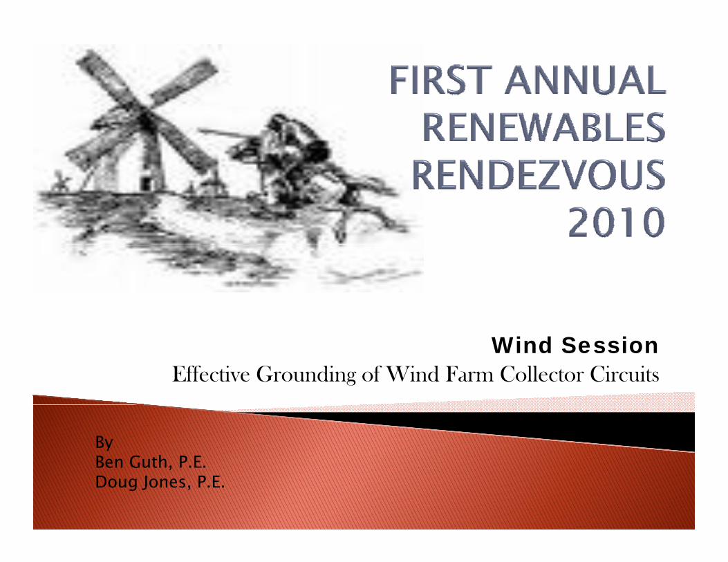
What is transient overvoltage (TOV)?What is the cause of TOV?OHow is TOV mitigated?Do all types of WTGs have problems with TOV? A d d ll i i i h i k f ll ?And do all mitigation techniques work for all types? How is TOV mitigating equipment specified?
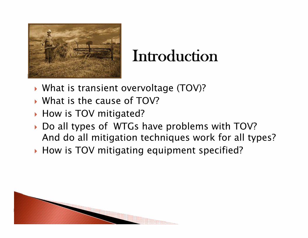
Must design an economical grounding system that: g g g y◦ controls TOV to acceptable levels◦ limits fault current while enabling secure ground fault
protectionpTransient Overvoltages (TOV) can lead to surge arrester and other equipment failureG di t f hi h d diGrounding transformers or high speed grounding switches usually provide adequate mitigationDifferent wind turbine types can mean different ypgrounding methods
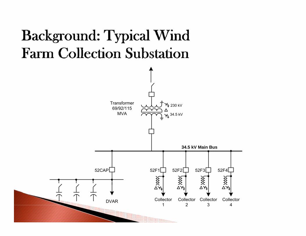
TransformerTransformer69/92/115
MVA
230 kV
34.5 kV
34.5 kV Main Bus
52F1 52F2 52F3 52F452CAP
Collector1
Collector2
Collector3
Collector4
DVAR
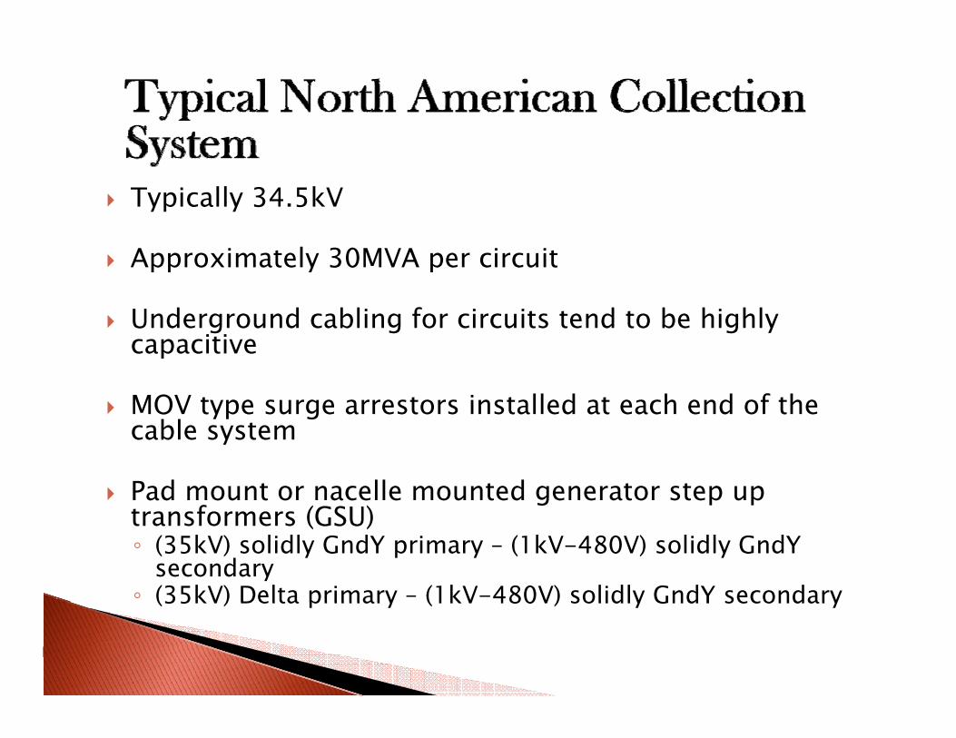
Typically 34.5kV
Approximately 30MVA per circuit
Underground cabling for circuits tend to be highlyUnderground cabling for circuits tend to be highly capacitive
MOV type surge arrestors installed at each end of the yp gcable system
Pad mount or nacelle mounted generator step up t f (GSU)transformers (GSU)◦ (35kV) solidly GndY primary – (1kV-480V) solidly GndY
secondary◦ (35kV) Delta primary – (1kV-480V) solidly GndY secondary(35kV) Delta primary (1kV 480V) solidly GndY secondary
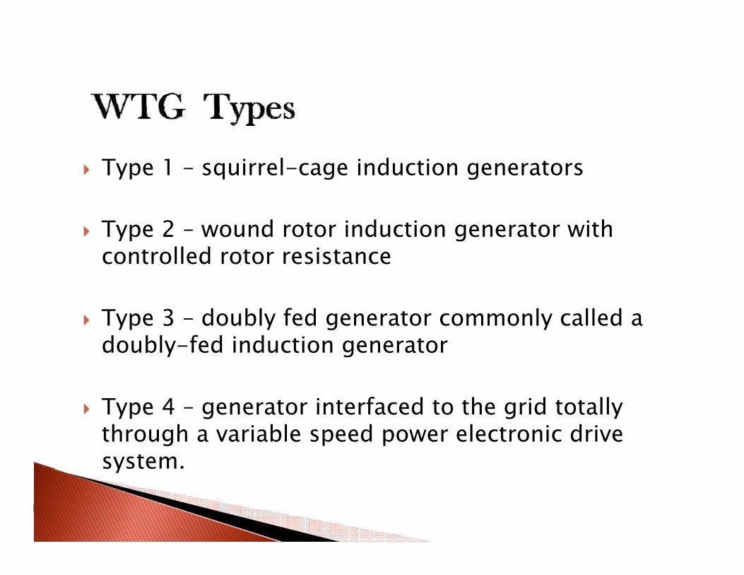
Type 1 – squirrel-cage induction generatorsyp q g g
Type 2 – wound rotor induction generator with t ll d t i tcontrolled rotor resistance
Type 3 – doubly fed generator commonly called aType 3 doubly fed generator commonly called a doubly-fed induction generator
Type 4 – generator interfaced to the grid totally through a variable speed power electronic drive system.y
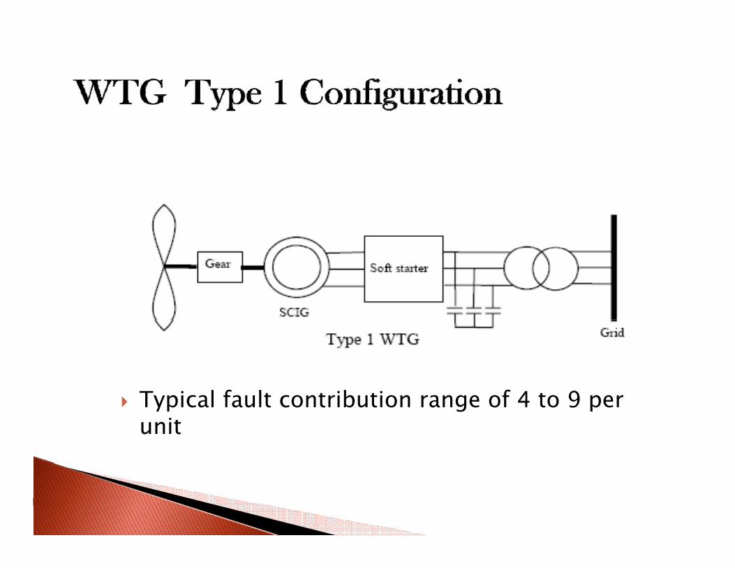
T i l f l ib i f 4 9Typical fault contribution range of 4 to 9 per unit
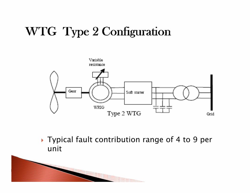
Typical fault contribution range of 4 to 9 per unit
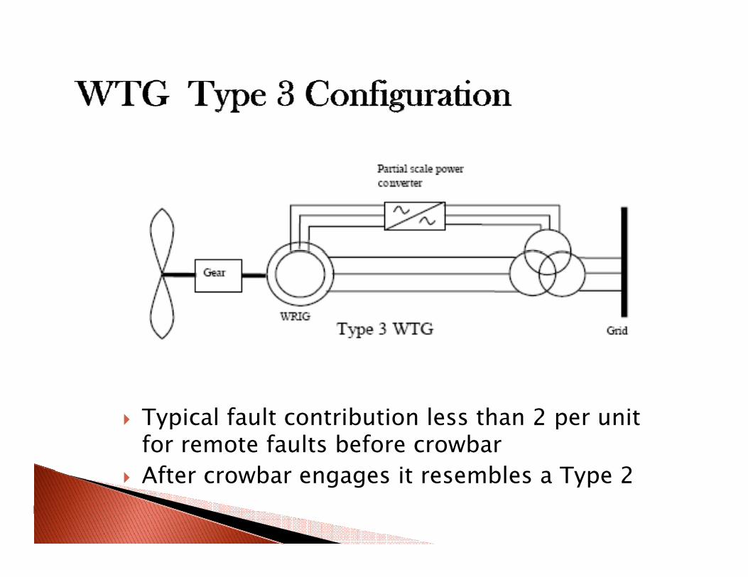
Typical fault contribution less than 2 per unit for remote faults before crowbarAft b it bl T 2After crowbar engages it resembles a Type 2
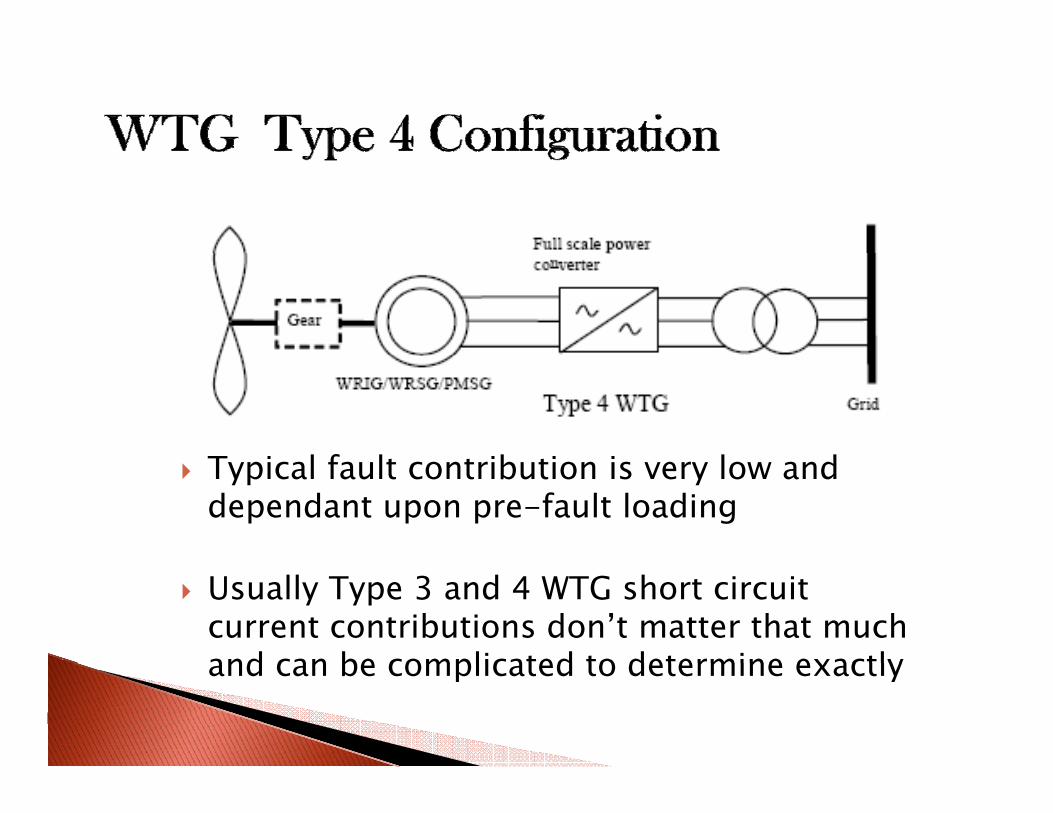
T i l f l ib i i l dTypical fault contribution is very low and dependant upon pre-fault loading
Usually Type 3 and 4 WTG short circuit current contributions don’t matter that much and can be complicated to determine exactlyand can be complicated to determine exactly
Ground fault
Inadvertent opening of circuit during generation
Capacitor bank switchingp g
Collection cable capacitanceCollection cable capacitance
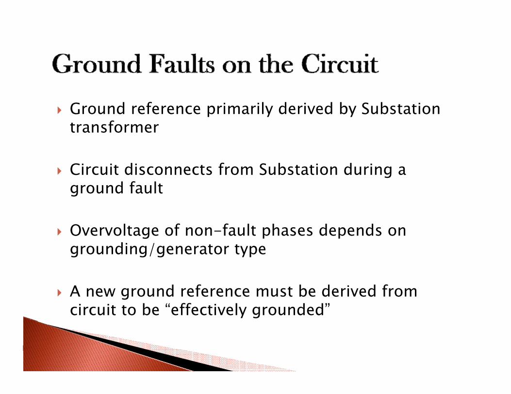
Ground reference primarily derived by Substation ftransformer
Circuit disconnects from Substation during aCircuit disconnects from Substation during a ground fault
Overvoltage of non-fault phases depends on grounding/generator type
A new ground reference must be derived from circuit to be “effectively grounded”
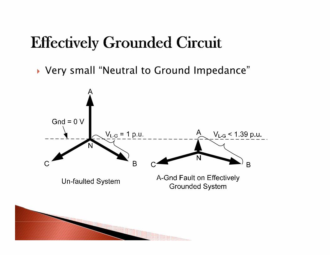
Very small “Neutral to Ground Impedance”
100
25
50
75[kV]
-25
0
25
0 00 0 05 0 10 0 15 0 20 0 25 0 30 0 35[s]-100
-75
-50
(file Cable.pl4; x-var t) v:G5NCA -X0004A v:G5NCB -X0004B v:G5NCC -X0004C 0.00 0.05 0.10 0.15 0.20 0.25 0.30 0.35[s]
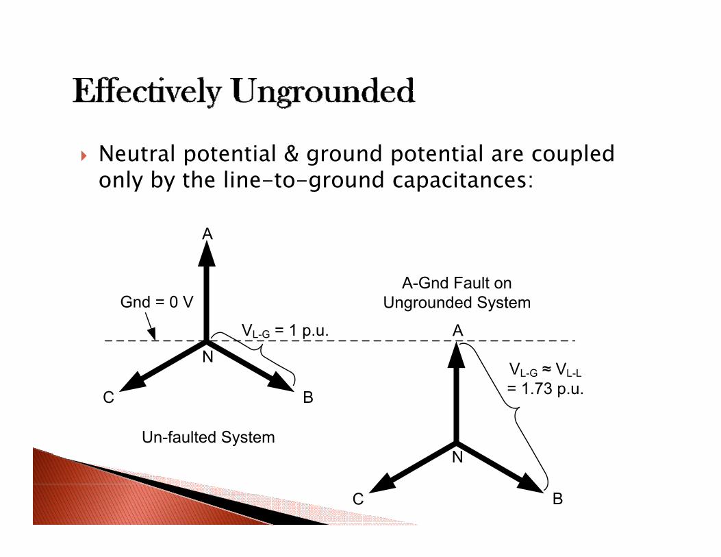
Neutral potential & ground potential are coupled l b h li d ionly by the line-to-ground capacitances:
A
Gnd = 0 VA-Gnd Fault on
Ungrounded System
NVL-G = 1 p.u.
VL-G ≈ VL-L1 73
A
C B = 1.73 p.u.
Un-faulted SystemNN
C B
100
25
50
75[kV]
-25
0
25
0 00 0 05 0 10 0 15 0 20 0 25 0 30 0 35[s]-100
-75
-50
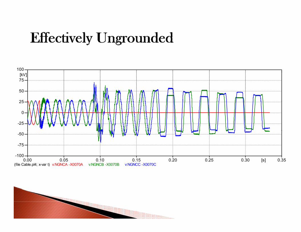
(file Cable.pl4; x-var t) v:NGNCA -X0070A v:NGNCB -X0070B v:NGNCC -X0070C 0.00 0.05 0.10 0.15 0.20 0.25 0.30 0.35[s]
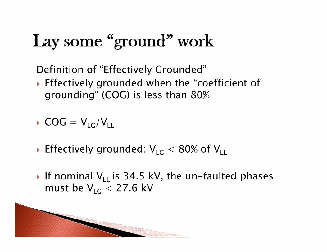
Definition of “Effectively Grounded”Effectively grounded when the “coefficient of grounding” (COG) is less than 80%
COG = VLG/VLL
Effectively grounded: VLG < 80% of VLL
If i l V i 34 5 kV th f lt d hIf nominal VLL is 34.5 kV, the un-faulted phases must be VLG < 27.6 kV
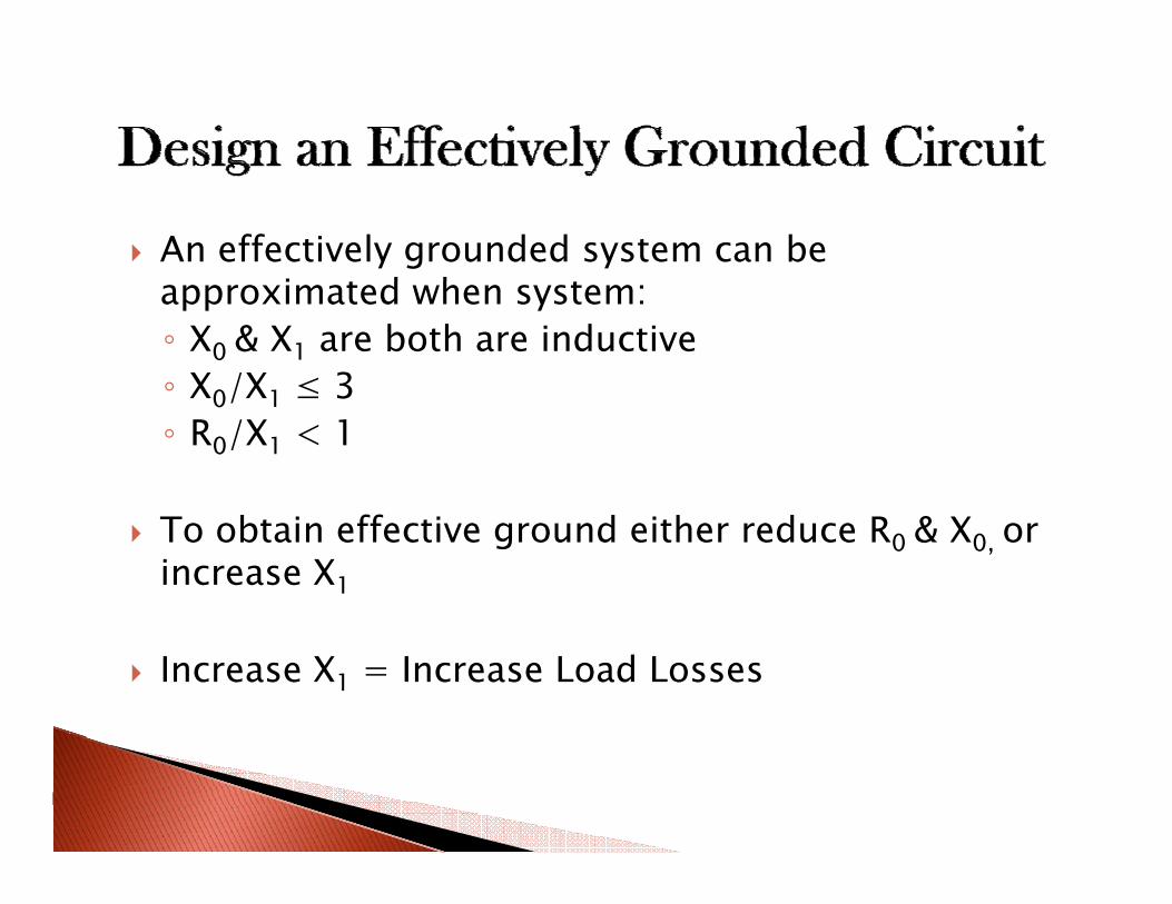
An effectively grounded system can be i d happroximated when system:
◦ X0 & X1 are both are inductive ◦ X0/X1 ≤ 3X0/X1 ≤ 3◦ R0/X1 < 1
To obtain effective ground either reduce R0 & X0, or increase X1
Increase X1 = Increase Load Losses
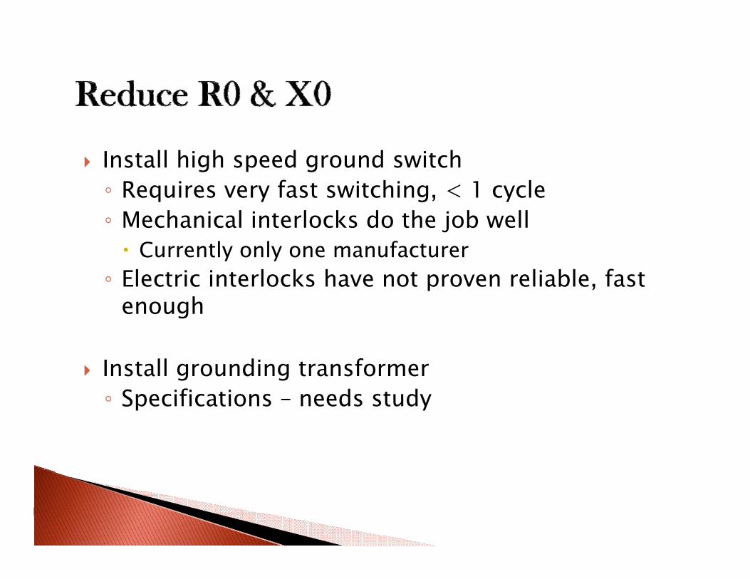
Install high speed ground switchf h l◦ Requires very fast switching, < 1 cycle
◦ Mechanical interlocks do the job wellCurrently only one manufacturerCurrently only one manufacturer
◦ Electric interlocks have not proven reliable, fast enough
Install grounding transformer◦ Specifications – needs study◦ Specifications – needs study
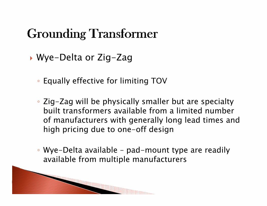
Wye-Delta or Zig-Zag
◦ Equally effective for limiting TOV
◦ Zig-Zag will be physically smaller but are specialty built transformers available from a limited number of manufacturers with generally long lead times and high pricing due to one-off design
◦ Wye-Delta available – pad-mount type are readily available from multiple manufacturers
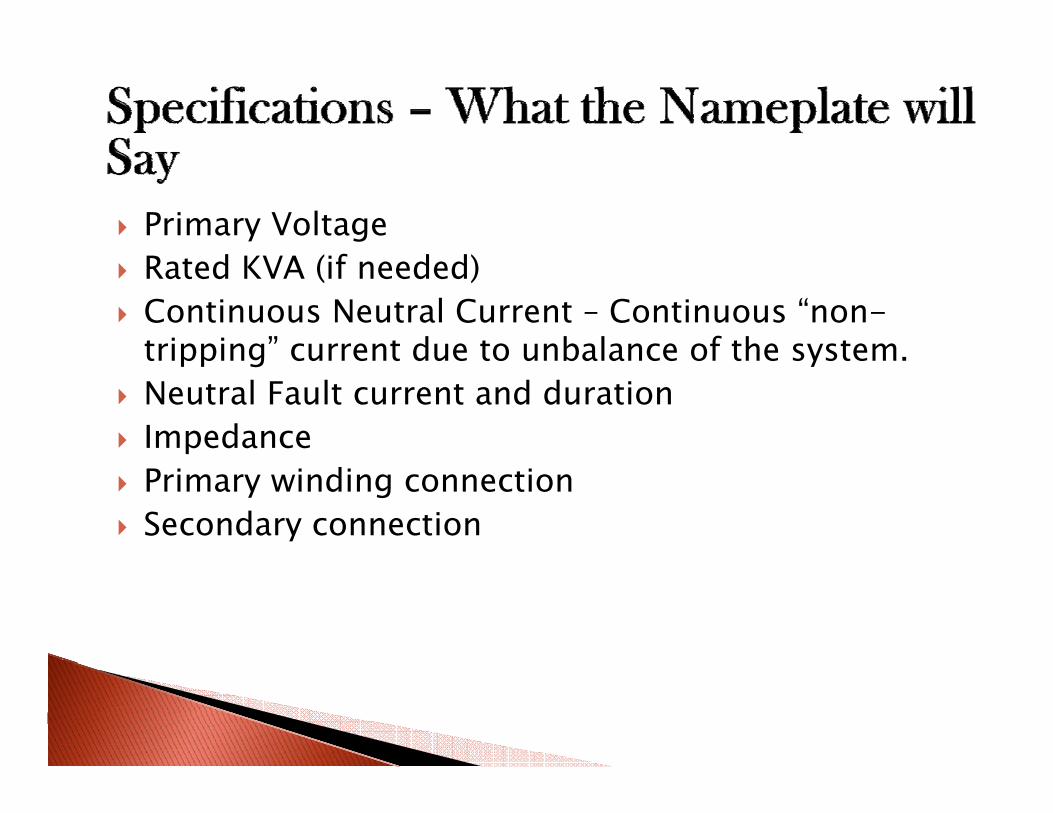
Primary VoltageRated KVA (if needed)Continuous Neutral Current – Continuous “non-tripping” current due to unbalance of the systemtripping current due to unbalance of the system. Neutral Fault current and durationImpedancePrimary winding connectionSecondary connection
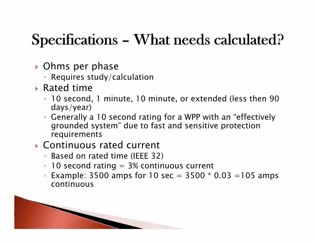
Ohms per phaseRequires study/calculation◦ Requires study/calculation
Rated time◦ 10 second, 1 minute, 10 minute, or extended (less then 90
days/year)days/year)◦ Generally a 10 second rating for a WPP with an “effectively
grounded system” due to fast and sensitive protection requirementsequ e e ts
Continuous rated current◦ Based on rated time (IEEE 32)◦ 10 second rating = 3% continuous current10 second rating 3% continuous current ◦ Example: 3500 amps for 10 sec = 3500 * 0.03 =105 amps
continuous
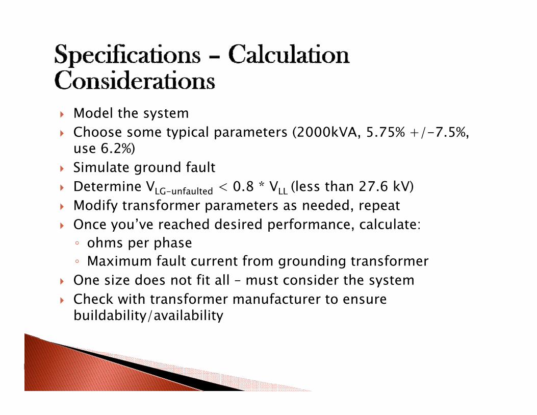
Model the systemCh t i l t (2000kVA 5 75% +/ 7 5%Choose some typical parameters (2000kVA, 5.75% +/-7.5%, use 6.2%)Simulate ground faultD i V 0 8 * V (l h 27 6 kV)Determine VLG-unfaulted < 0.8 * VLL (less than 27.6 kV)Modify transformer parameters as needed, repeat Once you’ve reached desired performance, calculate: ◦ ohms per phase◦ Maximum fault current from grounding transformerOne size does not fit all – must consider the systemyCheck with transformer manufacturer to ensure buildability/availability
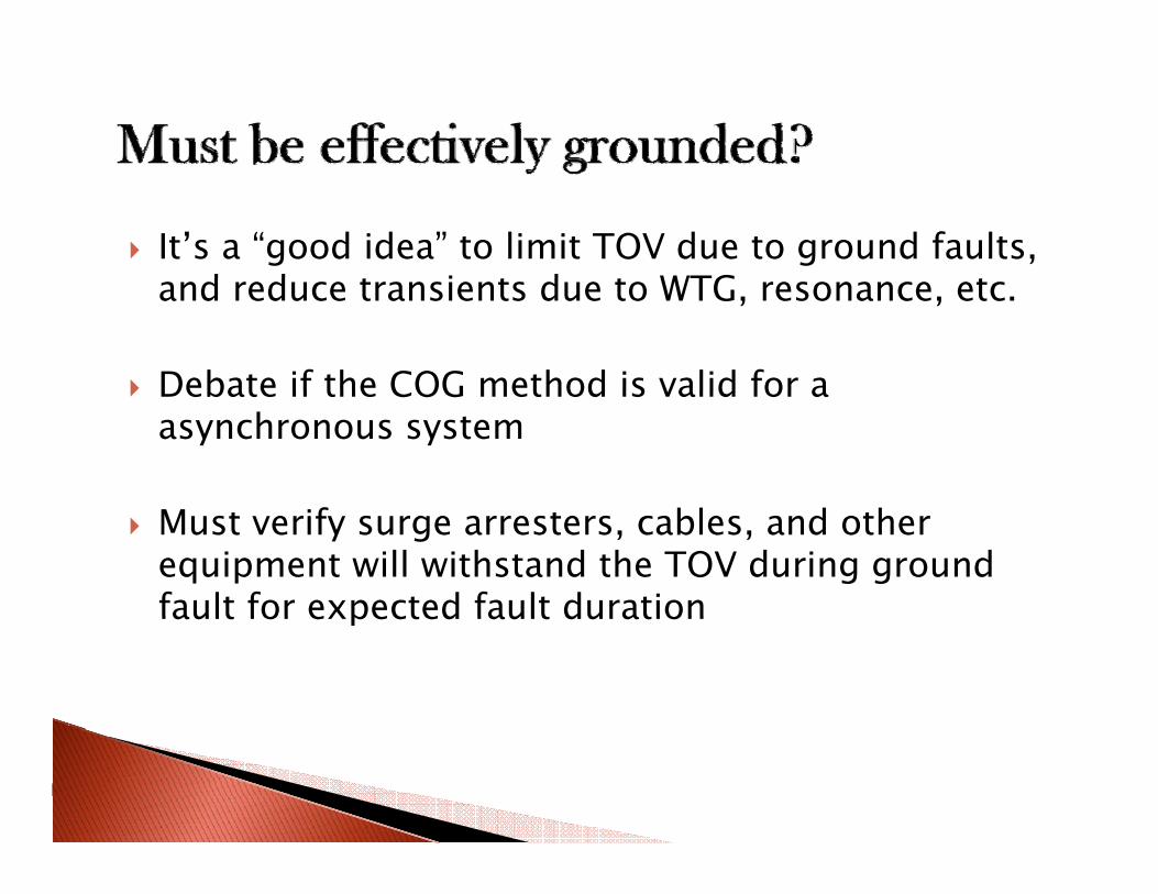
It’s a “good idea” to limit TOV due to ground faults, d d i d WTGand reduce transients due to WTG, resonance, etc.
Debate if the COG method is valid for aDebate if the COG method is valid for a asynchronous system
Must verify surge arresters, cables, and other equipment will withstand the TOV during ground fault for expected fault durationfault for expected fault duration
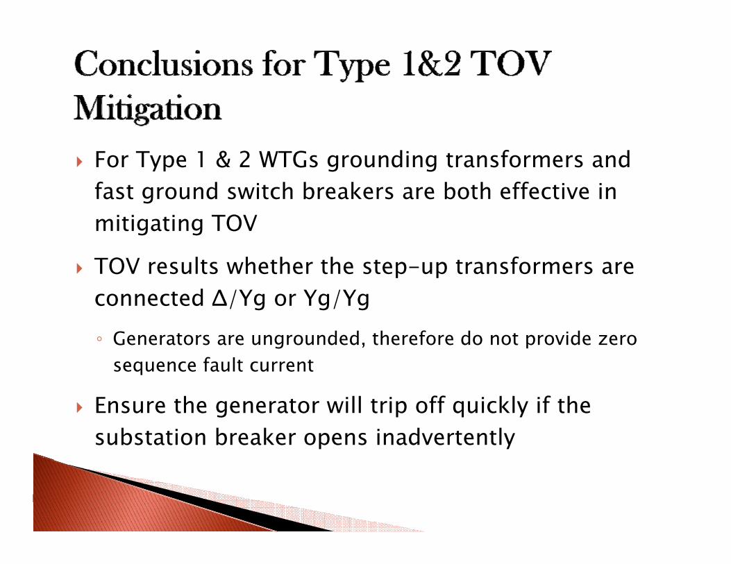
For Type 1 & 2 WTGs grounding transformers and fast ground switch breakers are both effective in mitigating TOV
TOV results whether the step-up transformers are connected Δ/Yg or Yg/Yg◦ Generators are ungrounded, therefore do not provide zero
sequence fault current
Ensure the generator will trip off quickly if the substation breaker opens inadvertently
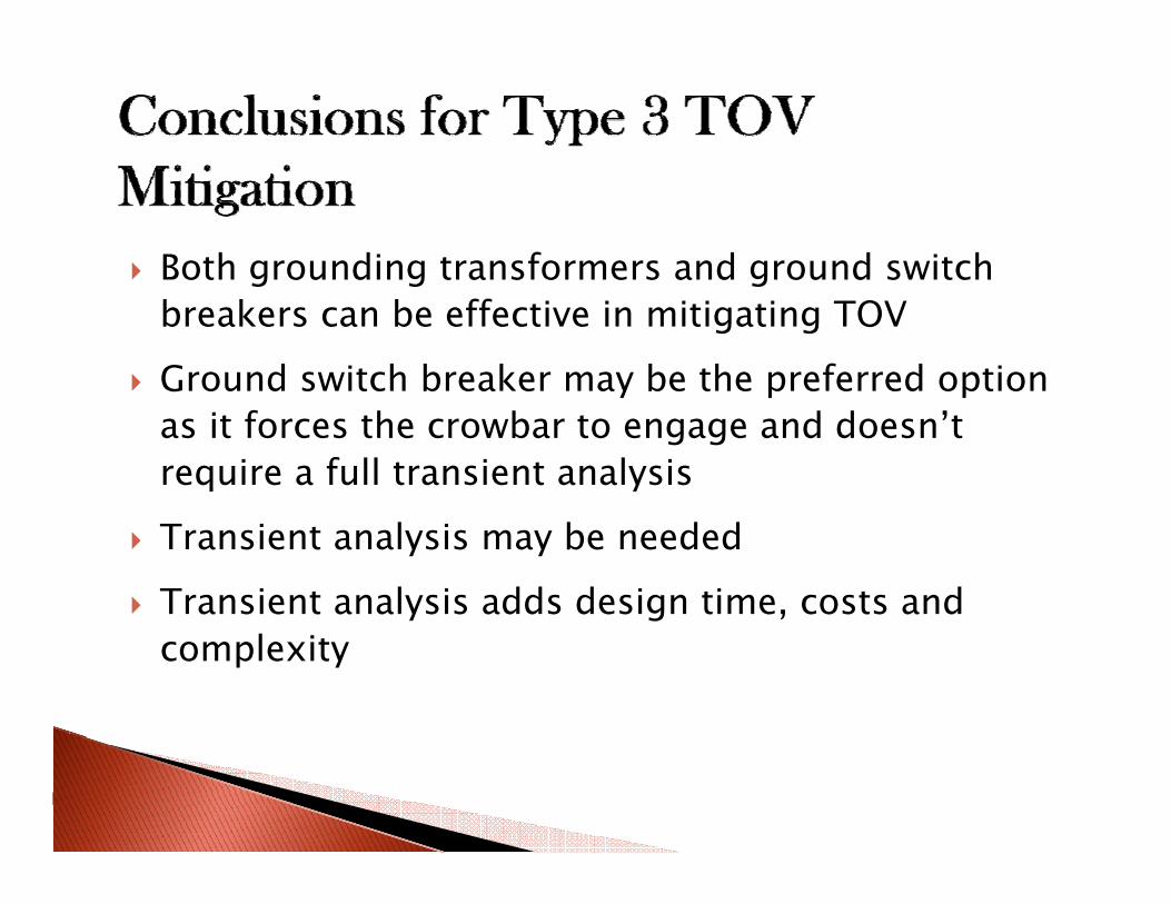
Both grounding transformers and ground switch g g gbreakers can be effective in mitigating TOV
Ground switch breaker may be the preferred option y p pas it forces the crowbar to engage and doesn’t require a full transient analysis
Transient analysis may be needed
Transient analysis adds design time, costs and complexity
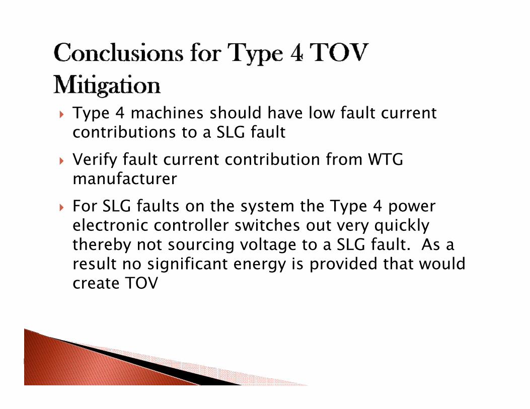
Type 4 machines should have low fault current ib i SLG f lcontributions to a SLG fault
Verify fault current contribution from WTG manufacturermanufacturerFor SLG faults on the system the Type 4 power electronic controller switches out very quicklyelectronic controller switches out very quickly thereby not sourcing voltage to a SLG fault. As a result no significant energy is provided that would create TOVcreate TOV

Questions
Chong Han, Don E. Martin, Member, IEEE, and Modesto R. lezama, “Transient Over-Voltage (TOV) and Its Suppression For a Large Farm interconnection”.
Eaton Application White Paper, “Transient Over voltages on Ungrounded Systems from Intermittent Ground Faults.
Pacific Crest Transformers Article, “Grounding Transformers” April, 02 2009.
St W S l P E ”L Wi d Pl t C ll t D i ”Wi d F C ll t S t G di IEEESteven W. Saylors, P.E., ”Large Wind Plant Collector Design ”Wind Farm Collector System Grounding, IEEE PES Transmission and Distribution Conference 2008.
Mike Reichard, “Fault Current Contributions From Variable Speed (Type 3 and 4) Wind Turbine Generators” Texas A&M Protective Relaying Conference Fault Current Contributions from Wind Plants April 1, 2009.p ,
ANSI/IEEE Std 32-1972 IEEE Standard Requirements, Terminology, and Test Procedures for Neutral Grounding Devices.
Reigh A. Walling, Michael L. Reichard, “Short Circuit Behavior of Wind Turbine Generators”
EMA VDH/GSMI brochure (Combined 34.5 kV Vacuum Circuit Breaker & Mechanically Interlocked), available online at: http://www.ema-sa.com.ar IEEE Standard C62.22-1997, Guide for the Application of Metal-Oxide Surge Arresters for Alternating-Current Systems.

![Temp. Grounding & Bonding [Report]...This Code defines minimum basic grounding and bonding required to trip the circuits and provide worker protection. It also provides sufficient](https://img.pdfslide.us/doc/110x75/5e8dad92ba23443342331d3f/temp-grounding-bonding-report-this-code-defines-minimum-basic-grounding.jpg)


![Wind Farm Collector System Grounding.ppt [Read-Only]ewh.ieee.org/conf/tdc/Saylors-Wind_Farm_Collector... · Wind Farm Collector System Grounding by Steven W. Saylors, P.E. ... Vestas](https://img.pdfslide.us/doc/110x75/5ac5a4b07f8b9aa0518e1c87/wind-farm-collector-system-read-onlyewhieeeorgconftdcsaylors-windfarmcollectorwind.jpg)