Embed Size (px)
Citation preview
."',......
Effect of Welding on Pressure Vessel Steels
Progress Report No.4 on
The Effect of Fabrication Processes on Steels
Used in Pressure Vessels
by
A. Scotchbrook, L. Eriv, R. D. Stout, and B. G. Johnston
Lehigh University
'Pressure Vessel Research COIDn1ittee
Welding Research Council

Effect of Welding on Pressure Vessel Steels
Progress Report 10.4 on the Effect of Fabrication Processes on
Steels Used in Pressure Vessels
A. F. Scotchbrook , L. Eriv", R. D. Stout, and B. G. Jolmston'
Introduction
The effect of fabrication processes on steels used in
pressure vessels is a subject to which considerable attention
has been devoted by the Fabrication Division of the Pressure
Vessel Research Committee of the Welding Research Council.
It is desired to know which fabrication operations are harmful
to the mechanical properties of steels, and to what extent.
Eventually this information should lead to materials specifi-
cations and to codes of recommended fabrication practice,
based on measured responRes of steel to various treatments.
With these objectives, the Pressure Vessel Research Committee
is sponsoring a project at Lehigh University.
In earlier investigation;,2,~ the effect of various
simulated fabrication operations was determined by measuring
the changes in transition temperature, strength and ductility
of the material. These fabrication processes included various
degrees of plastic pvestrain produced by uniaxial stress,
various (> heat treatments. 3
A. F. Scotchbrook and L. Eriv are~Research,Assistants',
at the Fritz Engineering Laboratory, Lehigh University,Bethlehem, Penna.
R. D. Stout is Associate Professor of Metallurgy, LehighUniversity.
Bo G. Johnston is Director, Fritz-EngineQring-Laboratoryand Professor of Civ11 Engineering, Lehigh University.
1, 2, 3. These numbers refer to references at the end of thisreport.

.. 2 ..
This report consid~rs another fabrication process
welding. It was desired to know how different grades of
Materials
For the tests reported here, six plain carbon steels
were selected from several mills to cover a range of grades,
research purposes. rthe others ~erEl.ord~@ from regular mill
stock. Samples for chemical analysis 'were taken from the
carbon contents and deoxida tionpractices. A complete his toryA-yo/~A-7o
is available2 for two of the steels used'l,each in two thick-(A,"YOI) (kj,7o) . ' (4-'YoV_)
nesses, Steels A/land E"of 5/S il thickness, and Steels B,Land F(fl;7D~.
of 1 1/4 11 thiclmess. These' steels were made especially for~~
steels .according to recommended A.S~T.M. procedure and the
results of these analyses are given in Table I. Also
included in Table I are strength and ductility data for the
as-rolled plate as determined by standard 0.505" tensile tests
at Lehigh University.
Specimen Preparation and Testing
The transition temperature of each steel was determined
for each of the follOWing conditions:
A. Welded
B•. Welded and heat treated at 5000 F
c. Vlielded and heat treated at 1l50oF
D. Elongated 5% and welded
E. Elongated 5%, welded and heat trea ted at 5000 F
F. Elongated at welded and heat treated at 11500 F5/0,

\\
This schedule was followed for two heat i I1Puts - 175 amperes,\
at 10 inches per minute with an E60l0 3/l6"electrode (called
Wl), and 275 amperes at S inches per minute with an E60l0 1/4"
electrode (called W2). To cut'down on expensive machining
operations, conditions Band E were not used for the 1 1/4"
plate (Steels B and F).
The longitudinal bead, notch-bend test, Figs 1, was
used as developedbya Welding Research Council project at
Lehigh University.,4 With an automatic welding machine, a
weld bead ten inches long was deposited on a plate surface
of the 3"x12" specimen. Heat treating was done one day
after welding. The 5/S" plate was then notched and tested
at plate thickn~ss, while the 1 1/4" plate was shaped down
on the unwelded surface to a thickness of 5/S" before notching~
Specimens were tested one week after welding.
The 5% prestrain for sections D" E and F above, was
produced by stretching strips 9 1/2" by 16' in an SOO,OOD
pound testing machine. Gage marks were scribed at two-foot
intervals along the strips and the distances between~&~~regularlYduring the pulling. -A two-foot section from". ~
each end of c~ strip~ was discarded to avoid using material
which had been non-uniformly deformed because of the restraints
at and pear the testing machine grips.
The spec-imens -were tes ted in bending, as in Fig. 2. TbJ."'ee
measurements were made on each specirp.en - percent lateral
contraction, percent of the .fracture area which was Cleavage,
and energy absorbed by the speeimen from the start of the
test until the load had passed its maximum and dropped to

- 4 -
a value equal to half the maximum. The percent contraction
values wero obtained by measuring with a pointed micrometer
the width of the specimen 1/32 inch below the notch bofore
and after the test o Percent cleavage measurements wore made
on a fractured section with a steol scale~ Energy vaJ.ues were
determined by measuring with a planimeter the area under a
load-deflection curve obtained· autographically during tho
tos t.

~ 5 -
TE, as described here, is a transition temperature
not previously determi.ned or reported in the earlier papel~s.
TE was found to agree very closely with TN for unst~ained
material, and to be consistently lower than TN for strained
material" Fig. 3 shows typical energy and contre.ction curves
for strained and unstrained material G
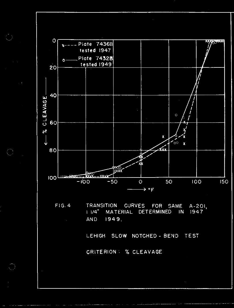
To determine the effects of welding) the transition
temperatures of welded specimens were compared with those of
unwelded specimens from the same material u Although transition
curves for the as-received condition had been made earlier
for steels Band Fl,3, they were repeated for use in the
present work. It was found that there were some differences
between the two sets of curves, which arc shown in Fig. 4 to
7. The discrepancies between the curves must be accounted for
by variation from plate to plate2 , and by inaccuracy caused
by the method of plotting. From these curves, it appears that
variations in transition temperature as high as 300 F could be
intrinsic to plate variations and to the testing and plotting
methods, and could not be attributed with surety to the
variable being studied.
Di~Qussion of Results
Effect of Welding As-Rolled Plate
Welding increased notch~sehsitivit~or as~received plate
when measured by %contraction or energy. The difference
bet~een unwelded and welded plate was shown by a significant
rise in the transition temperatures 'IN and TE, both of which
are affected by the material directly below the machined notch.

- 6 -
The rise in TN caused by welding as-received plate is shown
graphi.cally in Fig. 8" The order of transitio:1 temperatures
after welding was quite different from that befo~e wdlding.
The notch-sensitivity measured by fracture appearance
was little affected by wslding. This is 3hown in Fig. 9 by
a small rise, or even a drop, in TB values from unwelded to
welded plate.
Effect of Welding Prostrained Plate
As seen in Fig. 10, pl'lestraining often but not always
raised somewhat the transition temperatures of as-received
plate. The effect of welding this plastically prestrained
pIa to is shown in Figs t 11 and 12. As in the case of as-rolled
plate, the TN for stl'lained plate was significantly raised
by welding (Fig. 11). The TN level after welding strained
metal was a little higher than that after w~lding unstrained
metal (Fig. 13).
Vihen the effect of welding prestrained steel is considered
in the light of the transition temperature TB, in Fig. 12, it
can be seen that TB for strained steel was raised up to 750 P
by welding. TB for strained and welded plate was, in most"
cases, appreciably higher than that for unstrained and welded
plate (Fig. 14).
Effect of F:eat Input
In comparing the differences in level between WI and
W2 in Figs. 8, 9, 11 and 12, it may be noted that, except
in two cases, the two heat inputs resulted in about the same
transition temperature for theso plain carbon steels.

- 7-
Effect of Plato ThiclnloSS
It can be seen from Figso 8 to 11 that welding
u8us.,:Lly caused grea ter incroases in TN for Steels B a::::d F,
whic~ were welded at 1 1/4" thickness, than it did for the
other steels, :wolded at S/8 il thiclmoas. Since all the steels
'were tested in 5/8 1! 'Jch:i,01{J.:'')ss, this indicates that the increasG(~
cooling rate after welding' impos ed by the thicker pIa te resul to(~
in a higher TN transition temperature. The TB transition
temperature, Figs. 9 and 12, was changed by welding to about
the same degree for 1 1/411 and 5/8" plate.
Effect of Carbon Content and Deoxidation Practice
There appeared to be some correlation between carbon
content and transition temperatures, both before and after
wolding, as shown in Fig. 15. This figure contains only the
values for the steels of 5/8" thickness.
In Fig. 16 the steels are grouped according to deoxidation
practice. According to either TN or TB, the rimmed steels
had the highest transition tomperatures after welding, the
killed steel with aluminum addition next, followed by the semi
killed rand straight silicon-killed steels. It is interesting
to note that the four steels selected at random from mill
stock comparod favorably with the two pedigreed steels
prepared especially for research purposes~
Effect of Heat Treatment after Welding
The effect of a 5000 F heat treatment after welding
lffist':ained metal at the lower heat input is illustrated in
Fig, 17. The heat troatmont has little effect - it sometimes
lowered TN and TB slightly and sometimes raised them. The

...·8
l1500F posthoat, however (Fig. 18), lowered TN by as much
as 70 degrees, while TB 'lVas Unnffoc,ted.
Strained and welded motal, however, responded more
readily to heat treatment. In Fig. 19 it can be seen that
even the 5000 posthea t lowered TN somewhat~,Y11ati~! i t lef,~ TB
l.Jnchanged. The 11500 pGsthoat, as shown in Fig. 20, resulted
in a lowering ,of ~ by as much as 1000 , and also a consistent
10'wering of TB •.
The same responses were found after the higher hoat
input weld •.
Effect of Welding on Hardness
A study was made of the hardness of the material
.immediately below the. weld in all conditions. It revealed
little beyond the fact that welding increased the hardness in
this area, and that the 11500 postheat had ~ very slight
softening effect.
~
from the transition temperature of the unwelded plate.
2. Welding prestrained material resulted in a T],-r'
and TB of slightly higher level than welding unstrained platen
Summary
..
~1. Weld1ng~increased the notch-sensitivity
material~~.fl~J,d1 The increase could no t
of the
be predicted
3. Welding raised the TN transition temperature of thick
. plate more than thin plate.
4~ The level of transition temperature was apparently a
function of carbon content and decxidatJan practice.

- 9 -
5. An 11500 F hea tr·trea tmen t after welding grea tly
improved 'the material affected by the weld. A 500oF'post•
heat tmproved strained and welded material, but not unstrained
welded material.
Acknowledgmen ts
This work was sponsored by the Pressure Vessel Research
Committee of the Welding Research Council, which is directed
by William Spraragen. Walter Samans is Chairman of the
Pressure Vessel Research Committee and Boniface E. Rossi is
Executive Secretary. Harry Boardman is Chairman of the
Fabrication Division of the Pressure Vessel Research Committee,
which guided the project staff in this work.
The project was carried on jointly by the Fritz Engineering
Laboratory of the Civil Engineering Department, and the
Metallurgy Department of Lehigh University. The execution of
work was made possible by the cooperation of Kenneth R. Harpel,
laboratory foreman, and the entire laboratory staff.
References
1. Osborn, C.J., Scotchbrook, A.F., stout, R.D., and Johnston,
B. G., "Comparison of Notch Tests and Brittleness Criteria",
The vVelding Journal, 28(1), Research Suppl., 24-s to 33-s (1949::"
2. Osborn, C.J., Scotchbrook, A.F., Stout, R.D., and Johnston,
B.G .. , "Composition and Property Variation.of Two Steels",
The ~~lding Journal, 28(5), Research Suppl., 227-s to 235-s
(1949)"
B.G., i/Effect of Plastic Strain and Heat Treatment", The.

"
- 10 '"
Welding Journal; 28(8), Research Suppl., 337-s to 353-s (1949).
4~ Stout, R.D., McGeady, L.~~; Sun; C.P., Libsch, J.F., and
Doan, G.E., "Effect of Weldiz:.g on Ductility and Notch Sensitivit'JT
of Some ship SteelS", The Welding Journal, 26(6), Research
Suppl., 335-s to 357-s (1947).