Embed Size (px)
Citation preview
Proceedings of the 10th ASAT Conference, 13-15 May 2003 Paper ST-26 589
Military Technical College Kobry El-Kobbah
Cairo, Egypt 4PS,
4trie
10th International Conference On Aerospace Sciences&
Aviation Technology
EFFECT OF WASH-IN AND WASH-OUT ON THE FLUTTER CHARACTERISTICS OF COMPOSITE AIRCRAFT WINGS
ASHAWESH* M. G
ABSTRACT
In recent years composite materials are increasingly employed in a variety of aerospace applications because of its obvious merits. The present paper presents and discusses firstly the effect of the fibre orientations 0, bending-torsion material coupling, K on the eigenvalues and associated eigenvectors of a composite wing structure in a more realistic manner. The cantilevered composite wing structure is modeled in a way to simulate both Circumferentially Uniform Stiffness (CUS) and Circumferentially Asymmetric Stiffness (CAS) configurations. Secondly, the effect of wash-in and wash-out deformations on the flutter speed of both composite wing configurations. The wing models are generated using the finite element program FEMAP, v6 and analyzed using the standard FE software, MSC/NASTRAN, v70.5.
Results from both model configurations are compared and discussed. It is shown that bending frequency is decreasing with increasing the fibre angle, where as the torsion frequency is a maximum at 0=±30° and ±45° for the CAS and CUS wing models respectively. It is found that bending-torsion coupling is more beneficial to the torsion frequency compared to the bending frequency. The positive coupling stiffness, which causes the wash-in behaviour, is found to increase the flutter speed of composite wings compared to the wash-out behaviour. Further more, coupling material stiffness is more beneficial to the flutter speed as in the case of CAS wing model compared to the CUS wing model.
KEY WORDS
Aircraft composite structure, Composite material, Normal mode analysis, Flutter analysis, Finite element method, Material coupling.
Assistant professor, Department of Aeronautical Engineering, Engineering College, Tajoura, Libya.

Proceedings of the 10th ASAT Conference, 13-15 May 2003 Paper ST-26 590
INTRODUCTION
Modern aircraft tend to possess a high level of flexibility in order to lower the weight and to meet maneuverability requirements. As a result, there is a possibility that several aeroelastic phenomena occur which severely limit the flight envelope and performance. In the design of flight vehicles, flutter is a critical parameter that must be considered in the early stage of the design process to avoid any structural failure and loss of the vehicle.
The use of composite materials in aerospace applications improves the aeroelastic efficiencies of the aircraft. This is due to the prominent characteristics associated with the composite materials, namely, the high strength/stiffness to weight ratio and the controllable material properties that are not possessed by the conventional materials. Investigations of aeroelastic behaviour of laminated cantilever composite wings modeled as plate, beams and closed box structures have been the subject research [1-9] for more than fifteen years.
This paper discusses the effect of material bending-torsion coupling stiffness for different fibre angle, 0 (-90° to 90°) on the natural frequency and associated mode shapes and wash-in and wash-out deformations on the flutter speed for the Circumferentially Uniform Stiffness (CUS) and Circumferentially Asymmetric Stiffness (CAS) configurations. In this work, the wing structure is considered as a closed thin-walled structure with the structural dimensions and material properties given in [10]. The root sections of the wing models are fixed to simulate a cantilevered boundary condition.
Results referred in the form of eigenvalues and associated eigenvectors in the case of free vibration analysis, which is considered as the main dynamic characteristics of the composite wing structure, and velocity versus the total damping in the case of flutter analysis.
Representative finite element models simulating the CUS and CAS configurations as developed in [9-11] are subsequently constructed. Material bending-torsion coupling stiffness is present in the case of CAS configuration, where as vanishes in the CUS configuration, but bending and torsion rigidities are the same in both configurations. The finite element models generated, using FEMAP v6.0, and analyzed using standard FE software, MSC/NASTRAN v70.5 is described.
Results of both wing configurations are further compared for different fibre orientations. It is shown that wash-in deformation is more beneficial to the flutter speed than the wash-out deformation in the case of CAS model. On the other hand both deformations are beneficial to the flutter speed compared to the CUS model configuration.
Proceedings of the 10" ASAT Conference, 13-15 May 2003 Paper ST-26 591
FINITE ELEMENT MODELS AND ANALYSIS
The un-swept closed thin-walled structure of [10] is used in this paper. The dimensions of the wing structure are 762 mm, 24.21 mm and 13.46 mm length, width and height respectively. The laminate configuration or layups in the upper and lower skin and front and rear spars is in the form of [06] with the material properties presented in table 1.
Table 1 Material properties of the composite wing structure.
Ell = 142x103 N/mm2 p = 1.60 x 10⁻⁶ Kg/mm3 E22 = 9.8x10³ N/mm2 v12 = v13 =0.42, v23 = 0.5 G12 = G13 = 6.0x10³ N/mm2 ply thickness = 0.127 mm G23 = 4.83x10³ N/mm2
Where, E11 is the young's modulus of elasticity in the fibre direction, En is the young's modulus of elasticity in the transverse direction, G12 is the shear modulus in both directions, v12 is the Poisson's ratio and p is the density of the material.
The composite wing structure described above is modeled using a structural idealization program FEMAP v6 and analyzed using MSC/NASTRAN v70.5 based on the finite element method. All sides of the structure are modeled using CQUAD4 shell flat plate element with four grid points. The CQUAD4 element is represented by fully coupled laminate equation and can count for all coupling effects introduced through unbalanced laminates. The finite element of the wing model (total 288 nodes) consists of 280 quadrilateral (CQUAD4) shell plate elements. The verifications of the elements are checked and the material coordinate system is defined for both wing models according to [12]. The wing model is cantilevered at the root.
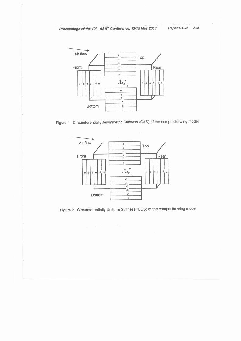
Two model configurations are selected in the modeling of the composite structure, namely, uniform or balanced (CUS) and asymmetric (CAS), [9-11]. In CAS configuration, the ply lay-ups on opposite sides are mirror images with respect to the mid-axis. But in case of balanced (CUS) configuration, the opposite sides are in opposite sign of fibre orientations as shown in figs. 1-2. Bending-twist coupling stiffness is produced in the case of asymmetric configuration (CAS), where as extension-twist coupling stiffness in the CUS case, [9-11]. The clockwise direction is taken as positive direction of the fibre angle, G.
Normal mode analysis is carried out on the above wing models to obtain the dynamic characteristics (natural frequency and mode shapes) using the Lanczos method provided by the analyzer MSC/NASTRAN.
Proceedings of the 10th ASAT Conference, 13-15 May 2003 Paper ST-26 592
The aerodynamic model of the wings is taken as a flat plate lifting surface with 159 boxes (40 spanwise and 4 chordwise) using the Doublet Lattice method. The aerostructural interconnection is defined by one surface spline. A flutter analysis is then carried out at M=0.4 using the PK method.
RESULTS AND DISSUCTIONS
The undamped free vibration analysis is done for the composite wing models. The natural frequencies at 30° fibre are compared and agreed with [10] for the CAS and CUS wing models as presented in table 2.
Table 2 Comparison of the natural frequencies of CAS and CUS wing models with [10] at 9=30° fibre angle.
Mode No. Present (MSC/NASTRAN) Reference [10] CUS (Hz) CAS (Hz) CUS (Hz) CAS (Hz)
1 24.78 (B) 24.88 (BT) 23.8 (B) 24.080 (BT) 2 154.4 (B) 154.64 (BT) - 150.72 (BT) 3 428.74 (B) 427.20 (BT) - 421.20 (BT) 4 511.12 (T) 773.48 (TB) - -
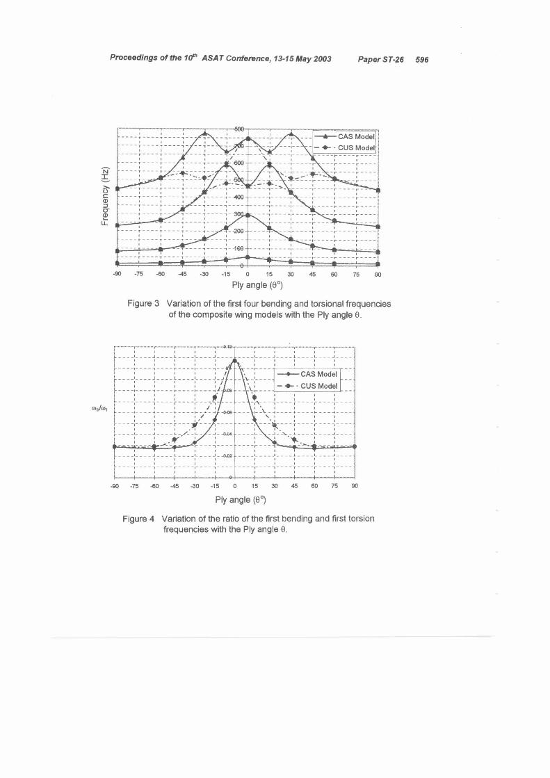
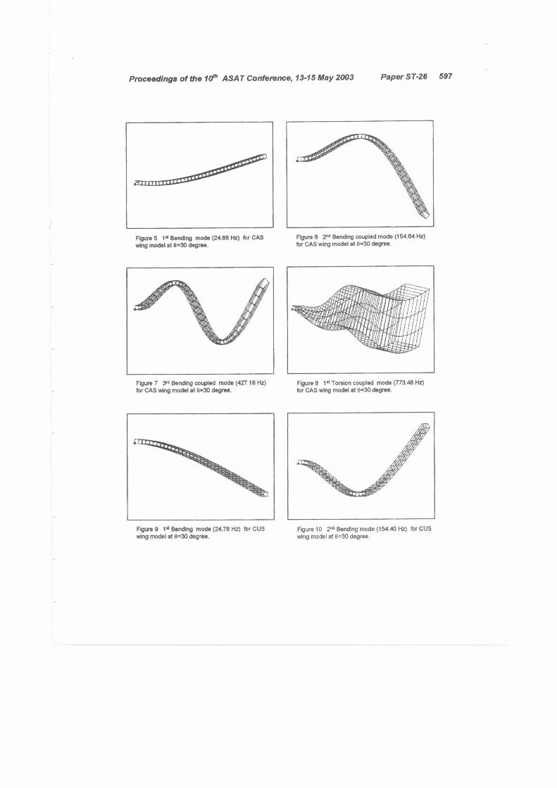
Figs. 3-4 show the variation of the first four bending and torsion natural frequencies and the bending and torsion frequency ratio as a function of the fibre angle for the two composite wing models respectively. The first natural frequency, which is characterized as a pure fundamental bending frequency in the case of CUS model and with a very small amount of twist in the case of CAS model for 0°<0<±90° decreases monotonically due to the reduction of the spanwise bending rigidity as shown in fig. 3. The second natural frequency is the second bending mode for CUS model and a dominated second bending with torsion in the case of CAS model for 0°<0<t90°. The third eigenvalue of the CUS wing model starts as the first torsion frequency for 0°<0.5t15°, and as a pure third bending frequency for t15°<0...±90° which is expected due to the modeling configuration. For the CAS model, the third frequency is a dominated third bending with twist for 0°<01-90°, and maximum tip twist is observed at ±15° ±30° as shown in figs. 5-8 at 9=30°. The fourth frequency of the CUS wing model is a third bending frequency for 0°<0±15°, and as a first torsion frequency for ±15°<0±45° as shown in figs. 9-12, and a fourth bending frequency for ±45°<090°. Finally the fourth frequency of the CAS model starts as dominated first torsion frequency mode with the large amount of bending for ±15° .t30° as shown in figs. 5-8, and then changes to a fourth bending with a twist for ±45°s0±90°.
From the above, the effect of bending-torsion material coupling stiffness (CAS model) is that the torsion frequency becomes higher as compared to the CUS wing model and
Proceedings of the 10th ASAT Conference, 13-15 May 2003 Paper ST-26 593
almost negligible on the bending frequencies. This effect is pronounced on the mode shapes as shown in figs. 5-8.
Due to the limited information's required for validation of flutter results for composite wings in the open literature. As a result a comparison of flutter results is required before dealing with flutter analysis of composite wing models. Therefore, the flutter analysis is then carried out on the detailed metal wing box presented in [13]. The flutter speed obtained by present work and [13] is 239.80 m/sec and 243.84 m/sec respectively with less than 1% difference.
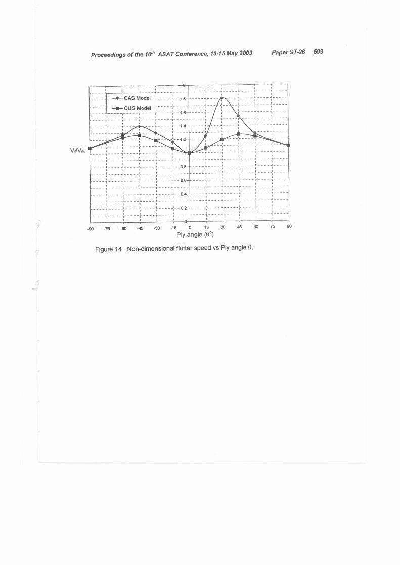
Fig. 13 shows for illustration, the variation of the flight speed versus the damping based on V-g plots using the PK method for 0° fibre angle. The flutter speed is considered as the speed at which the damping is zero. The flutter speeds for the above wing models for ply angles (-90° to 90°) are shown in fig. 14. In this figure, Vf is the actual flutter speed of the laminated wing model and Vfo is the corresponding flutter speed when the fibre orientation in each of the plies in the laminate representing the wing is set to zero. As shown in fig. 14, the maximum achievable flutter speed occurs when the fibre angle 0 is around 30 degree where the bending-torsion coupling is a maximum, giving a Vf/ Vf 0
ratio of about 1.80. At this fibre angle the wash-in behaviour is quite pronounced. On the other hand, when the fibre angle 0=-30° the CAS wing model exhibits wash-out behaviour. At fibre angle of 60°, the flutter speed is almost equal to the flutter speed at —60°, this is due to the small amount of material coupling present.
For the CUS wing model, the flutter speed is symmetrical about the zero fibre angle, this because there is no bending-torsion material coupling exist. The maximum flutter speed is obtained at 0=±45°, because at this angle the maximum torsion frequency is obtained. Fig. 14 shows that material coupling stiffness (wash-in and wash-out) is more beneficial to the flutter speed as compared to the CUS wing model.
CONCLUSIONS
Free vibration and flutter analysis are carried out on the Circumferentially Asymmetric Stiffness (CAS) composite wing model and Circumferentially Uniform Stiffness (CUS) composite wing model using the finite element programs, FEMAP and MSC/NASTRAN as preprocess, postprocess and analyzer respectively. The effect of material bending-torsion stiffness is negligible on the bending frequencies and pronounced on the torsion frequencies and mode shapes. The torsion frequency for the CAS wing model is much higher than the CUS wing model in the area where the coupling stiffness is high.
Positive bending-torsion coupling (wash-in) in the CAS wing model generally increases the flutter speed compared to the wash-out. Also, material coupling stiffness (wash-in and wash-out) is more favorable to the flutter speed in the CAS composite wing model compared to the CUS wing model.
Proceedings of the 10th ASAT Conference, 13-15 May 2003 Paper ST-26 594
REFERENCES
[1] Housner, J.M. and Stein, M., Flutter Analysis of Swept Wing Subsonic Aircraft with Parameter Studies of composite Wings, Nasa TN-D7539, Sept. 1974.
[2] Weisshaar, T.A., and Foist, B.L." Vibration Tailoring of advanced Composite Lifting surfaces" Journal of Aircraft, Vol. 22, No. 2, pp 141-147, 1985.
[3] Hollowell, S.J., and Dugundji, J. " Aeroelastic Flutter and Divergence of Stiffness Coupled, Graphite/Epoxy, Cantilevered Plates" Journal of Aircraft, Vol. 21, No. 1, pp 69-76, 1984.
[4] Weisshaar, T.A., and Foist, B.L." Vibration and Flutter of advanced Composite Lifting surfaces" Proceedings of the AIAA/ASME 24th Structures, Structural Dynamics and Material Conference, AIAA Paper 83-0961, pp 498-508, 1983.
[5] Weisshaar, T.A., and Ryan, J.R. " control of Aeroelastic Instabilities Through Stiffness Cross-Coupling" Journal of Aircraft, Vol. 23, No. 2, pp 148-155, 1986.
[6] Georghiades, G.A., Guo, S.J. and Banerjee, J.R. "Flutter Analysis of Composite Wings Using an Exact Dynamic Stiffness Matrix Method" Proceedings of the AIAA/ASME/ASCE/AHS/ASC 36th Structures, Structural Dynamics and Material Conference, AIAA Paper 95-1488, pp 3019-3027, 1995.
[7] Georghiades, G.A., Guo, S.J. and Banerjee, J.R. "An Insight into the flutter Characteristics of Laminated Composite Wings" Journal of Aircraft, Vol. 33, No. 6, pp 1204-1206, 1996.
[8] Pidaparti, R.M., Tischler, V.A., and Venkayya, V.B. "Flutter Prediction Methods for Aeroelastic Design Optimization" Journal of Aircraft, Vol. 38, No. 3, pp 557-559, 2001.
[9] Librescu, L.L., Meirovitch, 01., and Song, 0. "Refind Structural Modeling for Enhancing Vibrational and Aeroelastic Characteristics of Composite Aircraft Wings." La Recherche Aerospatiale, No. 1, pp 23-35, 1996.
[10] Armanios, E.A. and Badir A.M. "Free vibration Analysis of Anistropic thinwalled closed section beams." AIAA Journal, Vol. 33, No. 10, pp 1905-1910, 1995.
[11] Chandara, R., Stemple, A.D., and Chopra, I. "Thinwalled composite beams under bending, torsional, and extensional loads." Journal of Aircraft, Vol. 27, No. 10, pp 619-626, 1990.
[12] Rodden, P.W. and Johnson, H.E. "Aeroelastic Analysis Handbook for MSC/NASTRAN, Version 69, 1994, The Macneal-Schwendler Corporation.
[13] Rudisill, C.S. and Bhatia, K.G. " Optimization of Complex structure to satisfy flutter requirements" AIAA Journal, Vol. 9, No. 8, pp 1487-1491, 1971.
Proceedings of the 10th ASAT Conference, 13-15 May 2003 Paper ST-26 595
Air flow
Front
0 Top 0 0 0 Rear
0
0 0 0 0 0 0 0 0 0 0
Bottom
0 0 0 0
0
Figure 1 Circumferentially Asymmetric Stiffness (CAS) of the composite wing model
Figure 2 Circumferentially Uniform Stiffness (CUS) of the composite wing model
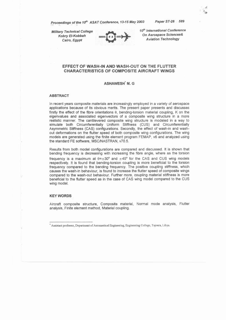
-90 -75 -60 -45 -30 -15 0 15
Ply angle (0°) 75 90
-11 J J
I 1 - — •-• - •-• •
I•
— — — — — — — — — —
-1- --t - -1- I
—4-- CAS Model — 40- - CUS Model
Proceedings of the 10th ASAT Conference, 13-15 May 2003 Paper ST-26 596
Figure 3 Variation of the first four bending and torsional frequencies of the composite wing models with the Ply angle 0.
y 41a I I I I I I I
1
-90 -75 -60 -45 -30 -15 0 15 30 45 60 75 90
Ply angle (0°)
Figure 4 Variation of the ratio of the first bending and first torsion frequencies with the Ply angle 0.
Proceedings of the 10th ASAT Conference, 13-15 May 2003 Paper ST-26 597
Figure 5 1= Bending mode (24.88 Hz) for CAS wing model at 0=30 degree.
Figure 8 2t= Bending coupled mode (154.84 Hz) for CAS wing model at 0=30 degree.
Figure 7 3,0 Bending coupled mode (427.18 Hz) for CAS wing model at 0=30 degree.
Figure 8 1° Torsion coupled mode (773.48 Hz) for CAS wing model at 0=30 degree.
Figure 9 1= Bending mode (24.78 Hz) for CUS wing model at 0=30 degree.
Figure 10 2r= Bending mode (154.40 Hz) for CUS wing model at 0=30 degree.

• •
-4- Point 1 -4-Point 2 -ar- Point 3 - Point 4 -4- Point 5 -4- Point 6
3
1 • •
0
-1.5 - r
600
• • • -2.5 • •
300 350 400 450 500 550 Velocity (m/s)
Figure 13 Velocity vs Damping of the composite wing model for 0=0°.
^ 1̂
Proceedings of the 10m ASAT Conference, 13-15 May 2003 Paper ST-26 598
Figure 11 r Bending mode (428.74 Hz) for CUS wing model at 0=30 degree.
Figure 12 1" Torsion mode (511.12 Hz) for CUS wing model at 8=30 degree.
Proceedings of the 10th ASAT Conference, 13-15 May 2003 Paper ST-26 599
I
iI
—0—CAS Model - - - - .-:- - 4 0— - - - -. - - - - _ - -:- - - - - t - - - - I- - - - -
.1. ■ f J tCUS Model 1
. ■ le— - -4 - T. I. ■
r _ - r - - -5 1 -
. -:- 4:4-- I I I I I
J 1 . .
1 '1- 1 : 11
1
-I
I I -I l. 1 T' 08 1 _i L i
■ 1 1 1 1
I I i 1 -: i- 4 00 • 4 r 1 i
11- 5 5 I
-5 I 1 I.. 1 . -I
t I I- 1 _._J
1 i 02 I i
: e 1 i 1
1 - 4 1
. 4 T
\Wit,
-90 -75 -el, 45 -30 -15 0 15 30 60 75 90
Ply angle (00)
Figure 14 Non-dimensional flutter speed vs Ply angle 0.