Embed Size (px)
Citation preview
7/27/2019 Effect of Various Parameters on the Flapping Motion of an Aerofoil
http://slidepdf.com/reader/full/effect-of-various-parameters-on-the-flapping-motion-of-an-aerofoil 1/7
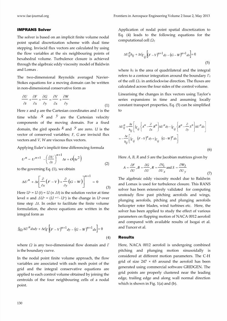
Frontiers in Aerospace Engineering Volume 2 Issue 2, May 2013 www.fae-journal.org
129
Effect of Various Parameters on the Flapping
Motion of an AerofoilSharanappa V. Sajjan1 , K. Siva Kumar2
1 Computational and Theoretical Fluid Dynamics Division, 2 Council of Scientific and Industrial Research, National
Aerospace Laboratories
Bangalore, Karnataka, India
[email protected]; [email protected]
Abstract
Unsteady Reynolds-averaged Navier-Stokes (RANS)
computations are presented for the flow past a flapping
NACA 0012 aerofoil to study the effect of various motion
parameters on the propulsive efficiency and thrust
coefficient. The RANS solver used to obtain the time-
accurate solutions is based on an implicit dual time stepping
scheme with finite volume nodal point spatial discretization.
The algebraic eddy viscosity model due to Baldwin and
Lomax is used for the turbulence closure. The motion
parameters considered are reduced frequency, amplitude of
the pitch and plunge motions and phase shift between them.
The computed results compare well with the available data
in the literature.
Keywords
Unsteady Flow; RANS Solver; Implicit Method; Dual Time
Stepping; Flapping Aerofoil
Introduction
In recent years, Micro Air Vehicles (MAVs),
Unmanned Air Vehicles (UAV’s) and Nano Air
Vehicles (NAV’s) are becoming increasingly important,
especially in the area of military/defence surveillance.
These are classified into fixed, rotary and flapping
wing air vehicles. At low range Reynolds number,
flapping wings are more efficient and more easilymanoeuvrable compared to fixed wings. Numerous
computational as well as experimental studies have
been conducted to investigate the kinematics and
dynamics of flapping wings.
Many important features of flapping aerofoil
behaviour are depicted by the classical linear theory.
Theodorsen developed compact expressions for forces
and moments of a flapping aerofoil under the
assumption of small perturbation for inviscid and
incompressible flow. The flow is divided into twoclasses: the non-circulating flow and the circulatory
flow due to wake vortices. The thrust force and the
power input experienced by the flapping aerofoil were
given by Garrick . Ho and Chen studied the unsteady
wake of a plunging Aerofoil NACA 0012 in a low
turbulence wind- tunnel by a miniature multiple hot-
wire probe at Reynolds number (2.1 × 10⁴ ~ 105),
reduced frequency (0 to 1), and mean angle of attack 5◦.
Under the condition of no dynamic stall, the near
wake consists of viscous and inviscid parts. The
viscous wake is, the result of the merging of two
boundary layers on the aerofoil, has high velocity
gradient and turbulence levels, and is limited to a very
thin region. The inviscid wake is caused by the
induced flow of the circulation around the plunging
aerofoil and is laminar and of large width. Andersonand Anderson et al. have obtained visualization and
force data for a plunging and pitching aerofoil moving
in a water tank facility over a large range of
amplitudes, frequencies, and phase angles. Propulsive
efficiency, as high as 87% is measured experimentally
under conditions of optimal wake formation. They
found that agreement between the experimental data
and numerical predictions of a non linear
incompressible unsteady potential-flow method is
good when either very weak or no flow separation
vortices forms. Isogai et al. simulated dynamic stall
phenomena around a flapping NACA 0012 aerofoil by
a Navier-Stokes code at a free stream Mach number of
0.3 and Reynolds number of 105. The Baldwin and
Lomax algebraic turbulence model is used in the
computation. They found that high propulsive
efficiency occurs for the case in which the pitching
oscillation advances 90 degree ahead of the plunging
oscillation and the reduced frequency is at some
optimum value, for which there appears no
appreciable flow separation in spite of large-amplitudeoscillations.
7/27/2019 Effect of Various Parameters on the Flapping Motion of an Aerofoil
http://slidepdf.com/reader/full/effect-of-various-parameters-on-the-flapping-motion-of-an-aerofoil 2/7

7/27/2019 Effect of Various Parameters on the Flapping Motion of an Aerofoil
http://slidepdf.com/reader/full/effect-of-various-parameters-on-the-flapping-motion-of-an-aerofoil 3/7
Frontiers in Aerospace Engineering Volume 2 Issue 2, May 2013 www.fae-journal.org
131
FIG. 1(a) C-H GRID AROUND NACA0012 AEROFOIL
FIG. 1(b) CLOSE UP VIEW OF GRID
The combined pitching and plunging oscillation of an
aerofoil is shown in Fig. 2. The plunging motion is
defined as the vertical motion at right angles to the
direction of uniform free stream velocity U ∞. The
NACA 0012 aerofoil with chord length c performs a
sinusoidal plunging. The position of the aerofoil is y (t)
given by
y (t) = yo sin (ω t) (8)
where t is physical time, ω the angular frequency.
FIG. 2 AEROFOIL IN COMBINED PITCHING AND PLUNGING
MOTION WITH A PHASE DIFFERENCE OF Φ = 90°
Plunge amplitude, yo , is positive in the upward
direction and the reduced frequency is given by, ./
∞= U ck ω
The instantaneous non-dimensional plunging velocity
is
)cos(/ t k hU y a ω =∞
(9)
where the dot denotes a differentiation with respect to
t and the non-dimensional plunge amplitude isha = yo /c.
The instantaneous effective angle of attack due to pure
plunging is
)sin(0 φ ω α α += t (10)
where the amplitude of pitching oscillation is0
α , φ is
the phase angle ahead of the plunging motion which is
also shown in Fig. 2. The instantaneous lift and thrust
coefficients are Cl and Ct , respectively. The
instantaneous pitching moment coefficient around the
pitching-pivot point is Cm (positive in the nose-up
sense).
The instantaneous input power co-efficient is
∞+−= U cC yC C ml p /)( α
(11)
The time-averaged lift coefficient, pitching moment
coefficient, thrust coefficient and input power
coefficient over an oscillation period are Cl , Cm , Ct and
C p respectively. The mean thrust coefficient is
therefore defined as
steadyd d t C C C )(+−= (12)
where Cd is the mean drag coefficient, averaged for one
flapping period. (Cd)steady is the steady drag of the non-
moving wing at its present mean angle of attack.
The propulsive efficiency is calculated from the ratio
between power output and power input.
If dimensionless coefficients are used, this is equal to
the ratio of mean thrust coefficient to mean power
input coefficient
( ) ( ) ( ) pt prop C C /=η . (13)
As it can be identified from Fig. 2, the combined
motion produces wave motion propagating in the x-
direction. It is clear that the origin of this wave motion
can be attributed to the coupled heaving and pitching
oscillations with a finite phase difference. When we
define the propagation velocity of the wave, the ratio
of wave velocity to free stream velocity depends on
the critical reduced frequency which in turn is a
function of pivot point a, α0/ ha and ϕ. However, the
behaviour of critical reduced frequency is still usefulto select the parameters such as k , ϕ , ha and α0 for

7/27/2019 Effect of Various Parameters on the Flapping Motion of an Aerofoil
http://slidepdf.com/reader/full/effect-of-various-parameters-on-the-flapping-motion-of-an-aerofoil 4/7
www.fae-journal.org Frontiers in Aerospace Engineering Volume 2 Issue 2, May 2013
132
which the numerical simulations are to be performed
for various combinations of k and ϕ. For this reason,
the behaviour of critical reduced frequency is studied
or simulated for the following two different plunge
amplitudes (ha),
1. ha = 1.0 , α0=20° , a = 0, M = 0.3 and Re = 1.0 × 10⁵
2. ha = 2.0, α0 = 10°, a = 0, M = 0.3 and Re = 1.0 × 10⁵
The present numerical simulations have been
performed for various combinations of k and Ф for
each of these two cases.
1. ha = 1.0, α0=20°, a = 0, M = 0.3 and Re = 1.0 × 10⁵
Table 1 shows the results optimized for maximum
propulsion efficiency, ηP and time-averaged thrust
coefficient, C ̅ t , respectively with respect to k for
ϕ = 90°, which have been compared with Navier-
Stokes results available in Isogai et al. The highest
propulsion efficiency of 79.8% with a time-averaged
thrust coefficient of 0.310 and the highest time-
averaged thrust coefficient of 0.6118 with propulsion
efficiency 43.10% are obtained. Fig. 3 shows the
coefficient of lift, drag and moment versus the angle of
attack for the final converged cycle. The pressure
contours are shown in Fig. 4.
TABLE 1 COEFFICIENT OF THRUST AND PROPULSION
EFFICIENCY FOR A PITCHING-PLUNGING NACA 0012AEROFOIL
k Coefficient of thrust Propulsive efficiency ×
100
Present
(RANS)
Isogai [6] Present
(RANS)
Isogai [6]
0.5 0.10090528 0.310 0.79840 0.725
0.6 0.20012392 0.466 0.78002 0.6994
0.7 0.31576321 0.524 0.75058 0.6742
0.8 0.44585174 0.566 0.70883 0.6205
0.9 0.51040155 0.595 0.53349 0.5815
1.0 0.57188636 0.6118 0.43102 0.500
2. ha = 2.0, α0 = 10°, a = 0, M = 0.3 and R e = 1.0 × 10⁵
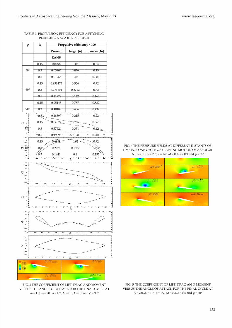
Table 2 and Table 3 show propulsion efficiency (ηP)
and time-averaged thrust coefficient (C ̅ t) respectively
which are compared against ϕ with k as a varying
parameter compared to the available results obtained
by Isogai et al. and Tuncer et al. both of who used a
Navier-Stokes code with Baldwin and Lomax
turbulence model. Although the agreements between
the two computations are fairly good for ϕ ≥ 60°, the
large quantitative discrepancies are seen in both ηP
and Ct for ϕ = 30°, in which case, the severe leading
edge-flow separations have been observed in our
computations for all of the reduced frequencies
computed, whereas no flow separation has beenobserved for k = 0.15 in the computations by Tuncer
and Platzer. It is interesting to see their results that the
highest C ̅ t is obtained for k = 0.15 and ϕ = 60°. It is
clear that the low values of C ̅ t and poor efficiency
obtained for k = 0.5 can be attributed to the occurrence
of large-scale leading-edge separation. The highest
propulsion efficiency of 95.14% with a time-averaged
thrust coefficient of 0.0875 and the highest time-
averaged thrust coefficient of 0.3168 with propulsion
efficiency 19.09% are obtained. Fig. 5 shows the
coefficient of lift, drag and moment versus the angle of
attack for the final converged cycle. The Mach number
contour at different instants of time for one complete
cycle of flapping motion of the aerofoil is plotted in
Figs. 6. The critical flow patterns are well captured and
flow separations are seen clearly in the plots. There is
a difference in predicted propulsion efficiency and
time-averaged thrust coefficient values and that of
Isogai et al. at smaller reduced frequencies is probably
due to the presence of viscous effects.
TABLE 2 COEFFICIENT OF THRUST FOR A PITCHING-PLUNGING NACA 0012 AEROFOIL
ϕ
k
Coefficient of thrust
Present
RANS Isogai [6] Tuncer [16]
30°
0.15 0.1267 0.1 1.4
0.3 0.01601 0.03 0.32
0.5 0.0178 0.04 0.1
60°
0.15 0.112166 0.71 1.325
0.3 0.131885 0.5 0.5989
0.5 0.17113 0.26 0.34
90°
0.15 0.08750 0.88 1.015
0.3 0.21918 0.706 0.752
0.5 0.28837 0.415 0.41
120°
0.15 0.08895 0.66 0.72
0.3 0.212377 0.74 0.725
0.5 0.316890 0.409 0.389
150°
0.15 0.1061 0.665 0.66
0.3 0.14267 0.4401 0.492
0.5 0.25199 0.26 0.2599
7/27/2019 Effect of Various Parameters on the Flapping Motion of an Aerofoil
http://slidepdf.com/reader/full/effect-of-various-parameters-on-the-flapping-motion-of-an-aerofoil 5/7
Frontiers in Aerospace Engineering Volume 2 Issue 2, May 2013 www.fae-journal.org
133
TABLE 3 PROPULSION EFFICIENCY FOR A PITCHING-
PLUNGING NACA 0012 AEROFOIL
ϕ
k Propulsive efficiency × 100
Present
RANS
Isogai [6] Tuncer [16]
30°
0.15 0.8098 0.05 0.64
0.3 0.03405 0.036 0.15
0.5 0.01265 0.05 0.089
60°
0.15 0.931473 0.556 0.72
0.3 0.271101 0.2722 0.32
0.5 0.11772 0.142 0.164
90°
0.15 0.95145 0.787 0.832
0.3 0.40189 0.406 0.432
0.5 0.18597 0.215 0.22
120°
0.15 0.81822 0.765 0.865
0.3 0.37524 0.391 0.42
0.5 0.19096 0.198 0.201
150°
0.15 0.6952 0.62 0.72
0.3 0.2024 0.1982 0.2535
0.5 0.1441 0.1 0.152
FIG. 3 THE COEFFICIENT OF LIFT, DRAG AND MOMENT
VERSUS THE ANGLE OF ATTACK FOR THE FINAL CYCLE AT
ha = 1.0, α0 = 20°, a = 1/2, M = 0.3, k = 0.9 and φ = 90°
FIG. 4 THE PRESSURE FIELDS AT DIFFERENT INSTANTS OF
TIME FOR ONE CYCLE OF FLAPPING MOTION OF AEROFOIL
AT ha =1.0, α0 = 20°, a = 1/2, M = 0.3, k = 0.9 and ϕ = 90°
FIG. 5 THE COEFFICIENT OF LIFT, DRAG AN D MOMENT
VERSUS THE ANGLE OF ATTACK FOR THE FINAL CYCLE AT ha = 2.0, α0 = 10°, a = 1/2, M = 0.3, k = 0.5 and ϕ = 30°

7/27/2019 Effect of Various Parameters on the Flapping Motion of an Aerofoil
http://slidepdf.com/reader/full/effect-of-various-parameters-on-the-flapping-motion-of-an-aerofoil 6/7
www.fae-journal.org Frontiers in Aerospace Engineering Volume 2 Issue 2, May 2013
134
FIG. 6: THE MACH CONTOURS AT DIFFERENT INSTANTS OF
TIME FOR ONE CYCLE OF FLAPPING MOTION OF AEROFOIL
AT ha = 2.0, α0 = 10°, a = 1/2, M = 0.3, k = 0.5 and ϕ = 30°
Conclusions
The time-averaged thrust coefficient of a combined
pitching-plunging NACA 0012 aerofoil computed by
the RANS solver agrees fairly well with those obtained
by Navier-Stokes solutions in the literature. The effect
of various motion parameters on the time-averaged
thrust generation and propulsive efficiency has been
studied. The highest propulsive efficiency and the
highest thrust coefficient do not occur at the same
reduced frequency. Higher propulsive efficiency
usually occurs at lower reduced frequency, where ashigher thrust occurs at higher reduced frequency. As
the flow becomes more and more unsteady with
increasing reduced frequency, a large amount of
vorticity is shed from the trailing edge. At higher
values of pitching amplitude time histories of the
coefficient of lift, thrust, drag and moment are smooth
purely sinusoidal but, as the pitching amplitude is
decreased, the time histories of these coefficients are
not sinusoidal as their shape is deformed thus
resulting in the decrease in propulsion efficiency and
an increase in the thrust coefficient comparatively.The maximum propulsive efficiency and minimum
thrust for the range of cases considered in the present
study occur when the phase angle between pitching
and plunging motion is approximately 90°.
REFERENCES
Anderson, J. M., “Vorticity control for efficient propulsion”,
PhD Thesis, Massachusetts Institute of Technology and
Woods Hole Oceanographic Institution, 1996.
Anderson, J. M., Streitlien, K., Barrentt D. S. and
Triantafyllou, M. S., “Oscillating foils of high propulsive
efficiency”, J. Fluid Mech., Vol. 360, pp. 41–72, 1998.
Baldwin B. S. and Lomax, H. “Thin layer approximating and
algebraic model for separated turbulent flows”, AIAA
Paper 78-275, 1978.
Beam R. M. and Warming, R. F., “An Implicit Factored
Scheme for the Compressible Navier-Stokes Equations”,
AIAA Journal , Vol. 16, No. 4, pp. 393 – 402, 1978.
Dutta, P. K., Vimala Dutta and Sharanappa V. Sajjan, “RANS
Computation of Flow past Wind Turbine Blades”, Proc.,
of 7th Asian Computational Fluid Dynamics Conference,
Bangalore, 26th – 30th November, 2007 (Invited Paper).
Garrick, I. E., “Propulsion of a flapping and oscillating
Aerofoil”, NACA REPORT No. 567, May 1936.
Hall, M. G., “Cell Vertex Multi-grid Scheme for Solution ofthe Euler Equations”, RAE-TM-Aero 2029, Proc. Conf. on
Numerical methods for fluid dynamics, pp. 303 – 345,
1985.
Ho C. M. and Chen, S.H., “Unsteady wake of a plunging
Aerofoil”, AIAA Journal , Vol. 19, pp. 1492–1494, 1981Roy.
“Unsteady Aerodynamics”, Proc. Two Day Conf., Aero.
Soc., London, 17- 18 July 1996.
Isogai, K., Shinmoto Y. and Watanabe, Y., “Effects of
dynamic stall on propulsive efficiency and thrust of
flapping Aerofoil”, AIAA Journal , Vol. 37, pp. 1145–1151,
1999.
Jameson, A., Schmidt W. and Turkel, E., “Numerical
Solution of Euler Equations by Finite Volume Methods
Using Runge Kutta Time Stepping Schemes”, AIAA
Paper 81 – 1259, 1981.
Sharanappa V. Sajjan, Vimala Dutta and Dutta, P. K.,
“Numerical Simulation of Flow over Pitching Bodies
using an implicit Reynolds-averaged Navier-Stokes
Solver”, Proc. of 12th Asian congress of Fluid Mechanics,
Daejeon, Korea, 18th – 21st , August 2008.

7/27/2019 Effect of Various Parameters on the Flapping Motion of an Aerofoil
http://slidepdf.com/reader/full/effect-of-various-parameters-on-the-flapping-motion-of-an-aerofoil 7/7
Frontiers in Aerospace Engineering Volume 2 Issue 2, May 2013 www.fae-journal.org
135
Sharanappa V. Sajjan, Vimala Dutta and Dutta, P. K.,
“Viscous Unsteady Flow around a Helicopter Rotor
Blade in Forward Flight”, Proc., 9th Annual CFD
Symposium, CFD Division of Aeronautical Society of
India, Bangalore, August 11-12, 2006.
Siva Kumar K. and Sharanappa V. Sajjan, “Numerical
Simulation of Unsteady Flow over a Plunging Aerofoil
Using an Implicit Reynolds averaged Navier-Stokes
Solver”, NAL PD CF 1003, March 2010.
Siva Kumar K. and Sharanappa V. Sajjan, “Unsteady Flow
past a Combined Pitching and Plunging Aerofoil using
an Implicit RANS Solver”, Applied Mechanics and
Materials , Vol. 110 - 116, pp. 3481-3488, 2012.
Theodorsen, T., “General theory of aerodynamic instability
and the mechanism of flutter”, NACA REPORT No. 496,
May 1934.
Tuncer, I. H., Walz, R. and Platzer, M., “A computational
study on the dynamic stall of a flapping Aerofoil”, AIAA
Paper 1998-2519, June 1998.