Embed Size (px)
Citation preview
201 (2006) 3430–3437www.elsevier.com/locate/surfcoat
Surface & Coatings Technology
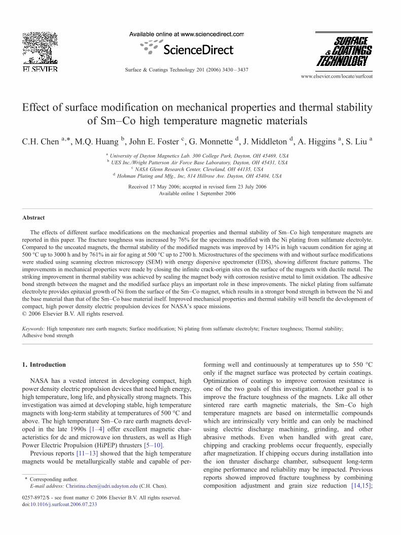
Effect of surface modification on mechanical properties and thermal stabilityof Sm–Co high temperature magnetic materials
C.H. Chen a,⁎, M.Q. Huang b, John E. Foster c, G. Monnette d, J. Middleton d, A. Higgins a, S. Liu a
a University of Dayton Magnetics Lab. 300 College Park, Dayton, OH 45469, USAb UES Inc./Wright Patterson Air Force Base Laboratory, Dayton, OH 45431, USA
c NASA Glenn Research Center, Cleveland, OH 44135, USAd Hohman Plating and Mfg., Inc, 814 Hillrose Ave. Dayton, OH 45404, USA
Received 17 May 2006; accepted in revised form 23 July 2006Available online 1 September 2006
Abstract
The effects of different surface modifications on the mechanical properties and thermal stability of Sm–Co high temperature magnets arereported in this paper. The fracture toughness was increased by 76% for the specimens modified with the Ni plating from sulfamate electrolyte.Compared to the uncoated magnets, the thermal stability of the modified magnets was improved by 143% in high vacuum condition for aging at500 °C up to 3000 h and by 761% in air for aging at 500 °C up to 2700 h. Microstructures of the specimens with and without surface modificationswere studied using scanning electron microscopy (SEM) with energy dispersive spectrometer (EDS), showing different fracture patterns. Theimprovements in mechanical properties were made by closing the infinite crack-origin sites on the surface of the magnets with ductile metal. Thestriking improvement in thermal stability was achieved by sealing the magnet body with corrosion resistive metal to limit oxidation. The adhesivebond strength between the magnet and the modified surface plays an important role in these improvements. The nickel plating from sulfamateelectrolyte provides epitaxial growth of Ni from the surface of the Sm–Co magnet, which results in a stronger bond strength in between the Ni andthe base material than that of the Sm–Co base material itself. Improved mechanical properties and thermal stability will benefit the development ofcompact, high power density electric propulsion devices for NASA's space missions.© 2006 Elsevier B.V. All rights reserved.
Keywords: High temperature rare earth magnets; Surface modification; Ni plating from sulfamate electrolyte; Fracture toughness; Thermal stability;Adhesive bond strength
1. Introduction
NASA has a vested interest in developing compact, highpower density electric propulsion devices that need high energy,high temperature, long life, and physically strong magnets. Thisinvestigation was aimed at developing stable, high temperaturemagnets with long-term stability at temperatures of 500 °C andabove. The high temperature Sm–Co rare earth magnets devel-oped in the late 1990s [1–4] offer excellent magnetic char-acteristics for dc and microwave ion thrusters, as well as HighPower Electric Propulsion (HiPEP) thrusters [5–10].
Previous reports [11–13] showed that the high temperaturemagnets would be metallurgically stable and capable of per-
⁎ Corresponding author.E-mail address: [email protected] (C.H. Chen).
0257-8972/$ - see front matter © 2006 Elsevier B.V. All rights reserved.doi:10.1016/j.surfcoat.2006.07.233
forming well and continuously at temperatures up to 550 °Conly if the magnet surface was protected by certain coatings.Optimization of coatings to improve corrosion resistance isone of the two goals of this investigation. Another goal is toimprove the fracture toughness of the magnets. Like all othersintered rare earth magnetic materials, the Sm–Co hightemperature magnets are based on intermetallic compoundswhich are intrinsically very brittle and can only be machinedusing electric discharge machining, grinding, and otherabrasive methods. Even when handled with great care,chipping and cracking problems occur frequently, especiallyafter magnetization. If chipping occurs during installation intothe ion thruster discharge chamber, subsequent long-termengine performance and reliability may be impacted. Previousreports showed improved fracture toughness by combiningcomposition adjustment and grain size reduction [14,15];
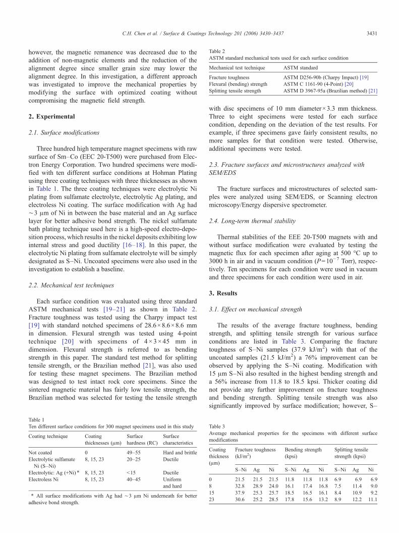
Table 2ASTM standard mechanical tests used for each surface condition
Mechanical test technique ASTM standard
Fracture toughness ASTM D256-90b (Charpy Impact) [19]Flexural (bending) strength ASTM C 1161-90 (4-Point) [20]Splitting tensile strength ASTM D 3967-95a (Brazilian method) [21]
3431C.H. Chen et al. / Surface & Coatings Technology 201 (2006) 3430–3437
however, the magnetic remanence was decreased due to theaddition of non-magnetic elements and the reduction of thealignment degree since smaller grain size may lower thealignment degree. In this investigation, a different approachwas investigated to improve the mechanical properties bymodifying the surface with optimized coating withoutcompromising the magnetic field strength.
2. Experimental
2.1. Surface modifications
Three hundred high temperature magnet specimens with rawsurface of Sm–Co (EEC 20-T500) were purchased from Elec-tron Energy Corporation. Two hundred specimens were modi-fied with ten different surface conditions at Hohman Platingusing three coating techniques with three thicknesses as shownin Table 1. The three coating techniques were electrolytic Niplating from sulfamate electrolyte, electrolytic Ag plating, andelectroless Ni coating. The surface modification with Ag had∼3 μm of Ni in between the base material and an Ag surfacelayer for better adhesive bond strength. The nickel sulfamatebath plating technique used here is a high-speed electro-depo-sition process, which results in the nickel deposits exhibiting lowinternal stress and good ductility [16–18]. In this paper, theelectrolytic Ni plating from sulfamate electrolyte will be simplydesignated as S–Ni. Uncoated specimens were also used in theinvestigation to establish a baseline.
2.2. Mechanical test techniques
Each surface condition was evaluated using three standardASTM mechanical tests [19–21] as shown in Table 2.Fracture toughness was tested using the Charpy impact test[19] with standard notched specimens of 28.6×8.6×8.6 mmin dimension. Flexural strength was tested using 4-pointtechnique [20] with specimens of 4 × 3×45 mm indimension. Flexural strength is referred to as bendingstrength in this paper. The standard test method for splittingtensile strength, or the Brazilian method [21], was also usedfor testing these magnet specimens. The Brazilian methodwas designed to test intact rock core specimens. Since thesintered magnetic material has fairly low tensile strength, theBrazilian method was selected for testing the tensile strength
Table 1Ten different surface conditions for 300 magnet specimens used in this study
Coating technique Coatingthicknesses (μm)
Surfacehardness (RC)
Surfacecharacteristics
Not coated 0 49–55 Hard and brittleElectrolytic sulfamate
Ni (S–Ni)8, 15, 23 20–25 Ductile
Electrolytic: Ag (+Ni) ⁎ 8, 15, 23 b15 DuctileElectroless Ni 8, 15, 23 40–45 Uniform
and hard
⁎ All surface modifications with Ag had ∼3 μm Ni underneath for betteradhesive bond strength.
with disc specimens of 10 mm diameter×3.3 mm thickness.Three to eight specimens were tested for each surfacecondition, depending on the deviation of the test results. Forexample, if three specimens gave fairly consistent results, nomore samples for that condition were tested. Otherwise,additional specimens were tested.
2.3. Fracture surfaces and microstructures analyzed withSEM/EDS
The fracture surfaces and microstructures of selected sam-ples were analyzed using SEM/EDS, or Scanning electronmicroscopy/Energy dispersive spectrometer.
2.4. Long-term thermal stability
Thermal stabilities of the EEE 20-T500 magnets with andwithout surface modification were evaluated by testing themagnetic flux for each specimen after aging at 500 °C up to3000 h in air and in vacuum condition (P=10−7 Torr), respec-tively. Ten specimens for each condition were used in vacuumand three specimens for each condition were used in air.
3. Results
3.1. Effect on mechanical strength
The results of the average fracture toughness, bendingstrength, and splitting tensile strength for various surfaceconditions are listed in Table 3. Comparing the fracturetoughness of S–Ni samples (37.9 kJ/m2) with that of theuncoated samples (21.5 kJ/m2) a 76% improvement can beobserved by applying the S–Ni coating. Modification with15 μm S–Ni also resulted in the highest bending strength anda 56% increase from 11.8 to 18.5 kpsi. Thicker coating didnot provide any further improvement on fracture toughnessand bending strength. Splitting tensile strength was alsosignificantly improved by surface modification; however, S–
Table 3Average mechanical properties for the specimens with different surfacemodifications
Coatingthickness(μm)
Fracture toughness(kJ/m2)
Bending strength(kpsi)
Splitting tensilestrength (kpsi)
S–Ni Ag Ni S–Ni Ag Ni S–Ni Ag Ni
0 21.5 21.5 21.5 11.8 11.8 11.8 6.9 6.9 6.98 32.8 28.9 24.0 16.1 17.4 16.8 7.5 11.4 9.015 37.9 25.3 25.7 18.5 16.5 16.1 8.4 10.9 9.223 30.6 25.2 28.5 17.8 15.6 13.2 8.9 12.2 11.1
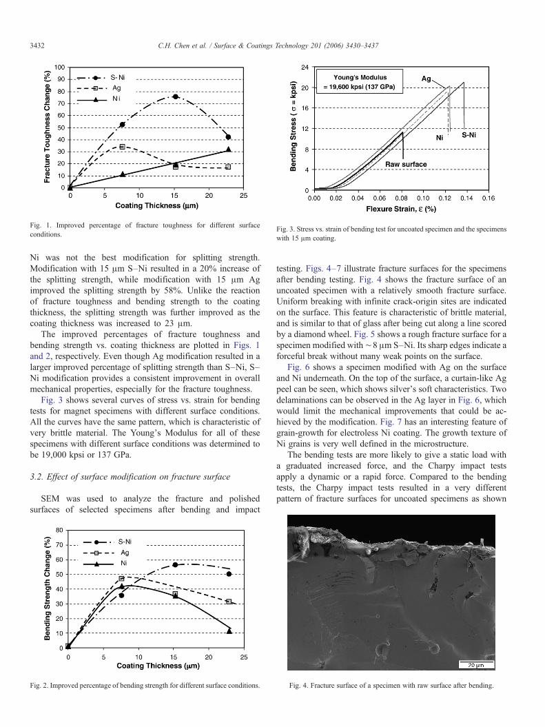
Fig. 3. Stress vs. strain of bending test for uncoated specimen and the specimenswith 15 μm coating.
Fig. 1. Improved percentage of fracture toughness for different surfaceconditions.
3432 C.H. Chen et al. / Surface & Coatings Technology 201 (2006) 3430–3437
Ni was not the best modification for splitting strength.Modification with 15 μm S–Ni resulted in a 20% increase ofthe splitting strength, while modification with 15 μm Agimproved the splitting strength by 58%. Unlike the reactionof fracture toughness and bending strength to the coatingthickness, the splitting strength was further improved as thecoating thickness was increased to 23 μm.
The improved percentages of fracture toughness andbending strength vs. coating thickness are plotted in Figs. 1and 2, respectively. Even though Ag modification resulted in alarger improved percentage of splitting strength than S–Ni, S–Ni modification provides a consistent improvement in overallmechanical properties, especially for the fracture toughness.
Fig. 3 shows several curves of stress vs. strain for bendingtests for magnet specimens with different surface conditions.All the curves have the same pattern, which is characteristic ofvery brittle material. The Young's Modulus for all of thesespecimens with different surface conditions was determined tobe 19,000 kpsi or 137 GPa.
3.2. Effect of surface modification on fracture surface
SEM was used to analyze the fracture and polishedsurfaces of selected specimens after bending and impact
Fig. 2. Improved percentage of bending strength for different surface conditions.
testing. Figs. 4–7 illustrate fracture surfaces for the specimensafter bending testing. Fig. 4 shows the fracture surface of anuncoated specimen with a relatively smooth fracture surface.Uniform breaking with infinite crack-origin sites are indicatedon the surface. This feature is characteristic of brittle material,and is similar to that of glass after being cut along a line scoredby a diamond wheel. Fig. 5 shows a rough fracture surface for aspecimen modified with∼8 μm S–Ni. Its sharp edges indicate aforceful break without many weak points on the surface.
Fig. 6 shows a specimen modified with Ag on the surfaceand Ni underneath. On the top of the surface, a curtain-like Agpeel can be seen, which shows silver's soft characteristics. Twodelaminations can be observed in the Ag layer in Fig. 6, whichwould limit the mechanical improvements that could be ac-hieved by the modification. Fig. 7 has an interesting feature ofgrain-growth for electroless Ni coating. The growth texture ofNi grains is very well defined in the microstructure.
The bending tests are more likely to give a static load witha graduated increased force, and the Charpy impact testsapply a dynamic or a rapid force. Compared to the bendingtests, the Charpy impact tests resulted in a very differentpattern of fracture surfaces for uncoated specimens as shown
Fig. 4. Fracture surface of a specimen with raw surface after bending.
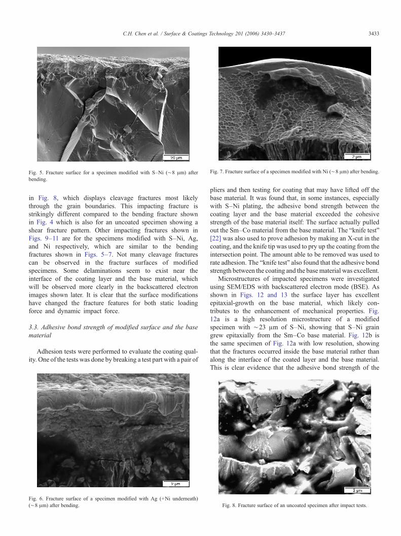
Fig. 7. Fracture surface of a specimen modified with Ni (∼8 μm) after bending.Fig. 5. Fracture surface for a specimen modified with S–Ni (∼8 μm) afterbending.
3433C.H. Chen et al. / Surface & Coatings Technology 201 (2006) 3430–3437
in Fig. 8, which displays cleavage fractures most likelythrough the grain boundaries. This impacting fracture isstrikingly different compared to the bending fracture shownin Fig. 4 which is also for an uncoated specimen showing ashear fracture pattern. Other impacting fractures shown inFigs. 9–11 are for the specimens modified with S–Ni, Ag,and Ni respectively, which are similar to the bendingfractures shown in Figs. 5–7. Not many cleavage fracturescan be observed in the fracture surfaces of modifiedspecimens. Some delaminations seem to exist near theinterface of the coating layer and the base material, whichwill be observed more clearly in the backscattered electronimages shown later. It is clear that the surface modificationshave changed the fracture features for both static loadingforce and dynamic impact force.
3.3. Adhesive bond strength of modified surface and the basematerial
Adhesion tests were performed to evaluate the coating qual-ity. One of the tests was done by breaking a test part with a pair of
Fig. 6. Fracture surface of a specimen modified with Ag (+Ni underneath)(∼8 μm) after bending.
pliers and then testing for coating that may have lifted off thebase material. It was found that, in some instances, especiallywith S–Ni plating, the adhesive bond strength between thecoating layer and the base material exceeded the cohesivestrength of the base material itself: The surface actually pulledout the Sm–Co material from the base material. The “knife test”[22] was also used to prove adhesion by making an X-cut in thecoating, and the knife tip was used to pry up the coating from theintersection point. The amount able to be removed was used torate adhesion. The “knife test” also found that the adhesive bondstrength between the coating and the base material was excellent.
Microstructures of impacted specimens were investigatedusing SEM/EDS with backscattered electron mode (BSE). Asshown in Figs. 12 and 13 the surface layer has excellentepitaxial-growth on the base material, which likely con-tributes to the enhancement of mechanical properties. Fig.12a is a high resolution microstructure of a modifiedspecimen with ∼23 μm of S–Ni, showing that S–Ni graingrew epitaxially from the Sm–Co base material. Fig. 12b isthe same specimen of Fig. 12a with low resolution, showingthat the fractures occurred inside the base material rather thanalong the interface of the coated layer and the base material.This is clear evidence that the adhesive bond strength of the
Fig. 8. Fracture surface of an uncoated specimen after impact tests.
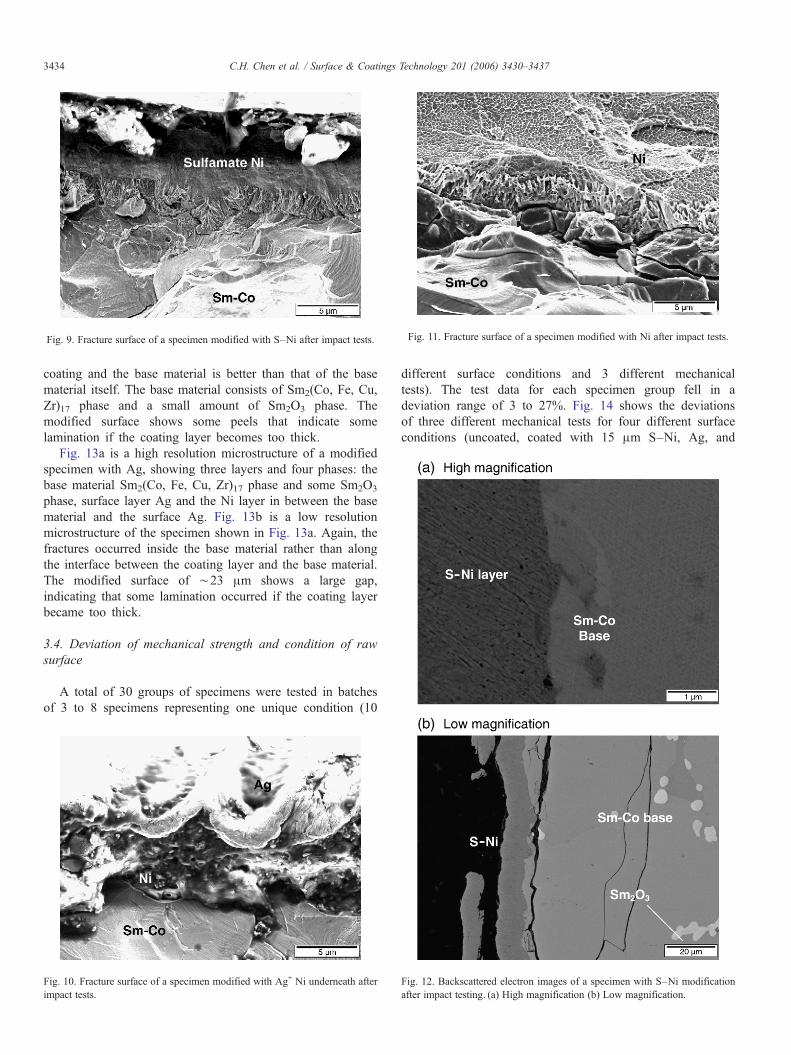
Fig. 9. Fracture surface of a specimen modified with S–Ni after impact tests. Fig. 11. Fracture surface of a specimen modified with Ni after impact tests.
3434 C.H. Chen et al. / Surface & Coatings Technology 201 (2006) 3430–3437
coating and the base material is better than that of the basematerial itself. The base material consists of Sm2(Co, Fe, Cu,Zr)17 phase and a small amount of Sm2O3 phase. Themodified surface shows some peels that indicate somelamination if the coating layer becomes too thick.
Fig. 13a is a high resolution microstructure of a modifiedspecimen with Ag, showing three layers and four phases: thebase material Sm2(Co, Fe, Cu, Zr)17 phase and some Sm2O3
phase, surface layer Ag and the Ni layer in between the basematerial and the surface Ag. Fig. 13b is a low resolutionmicrostructure of the specimen shown in Fig. 13a. Again, thefractures occurred inside the base material rather than alongthe interface between the coating layer and the base material.The modified surface of ∼23 μm shows a large gap,indicating that some lamination occurred if the coating layerbecame too thick.
3.4. Deviation of mechanical strength and condition of rawsurface
A total of 30 groups of specimens were tested in batchesof 3 to 8 specimens representing one unique condition (10
Fig. 10. Fracture surface of a specimen modified with Ag+ Ni underneath afterimpact tests.
different surface conditions and 3 different mechanicaltests). The test data for each specimen group fell in adeviation range of 3 to 27%. Fig. 14 shows the deviationsof three different mechanical tests for four different surfaceconditions (uncoated, coated with 15 μm S–Ni, Ag, and
Fig. 12. Backscattered electron images of a specimen with S–Ni modificationafter impact testing. (a) High magnification (b) Low magnification.
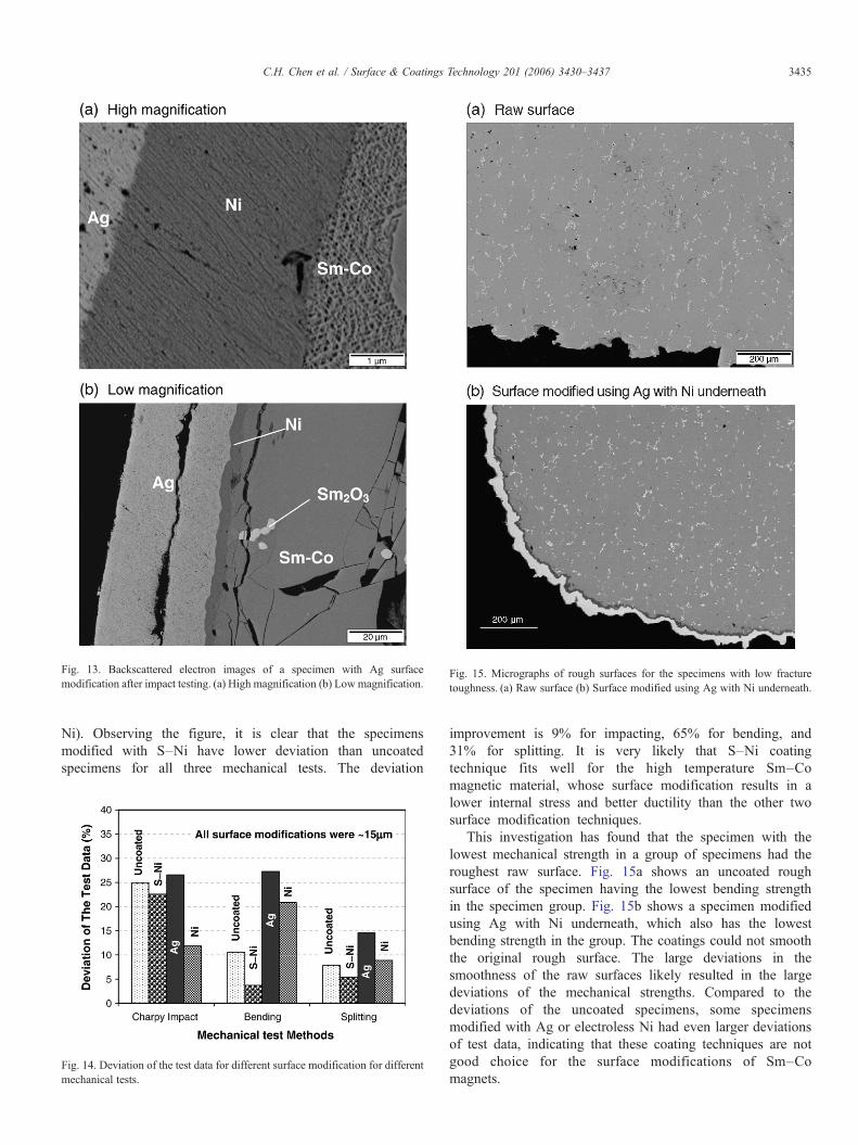
Fig. 13. Backscattered electron images of a specimen with Ag surfacemodification after impact testing. (a) High magnification (b) Low magnification.
Fig. 15. Micrographs of rough surfaces for the specimens with low fracturetoughness. (a) Raw surface (b) Surface modified using Ag with Ni underneath.
3435C.H. Chen et al. / Surface & Coatings Technology 201 (2006) 3430–3437
Ni). Observing the figure, it is clear that the specimensmodified with S–Ni have lower deviation than uncoatedspecimens for all three mechanical tests. The deviation
Fig. 14. Deviation of the test data for different surface modification for differentmechanical tests.
improvement is 9% for impacting, 65% for bending, and31% for splitting. It is very likely that S–Ni coatingtechnique fits well for the high temperature Sm–Comagnetic material, whose surface modification results in alower internal stress and better ductility than the other twosurface modification techniques.
This investigation has found that the specimen with thelowest mechanical strength in a group of specimens had theroughest raw surface. Fig. 15a shows an uncoated roughsurface of the specimen having the lowest bending strengthin the specimen group. Fig. 15b shows a specimen modifiedusing Ag with Ni underneath, which also has the lowestbending strength in the group. The coatings could not smooththe original rough surface. The large deviations in thesmoothness of the raw surfaces likely resulted in the largedeviations of the mechanical strengths. Compared to thedeviations of the uncoated specimens, some specimensmodified with Ag or electroless Ni had even larger deviationsof test data, indicating that these coating techniques are notgood choice for the surface modifications of Sm–Comagnets.
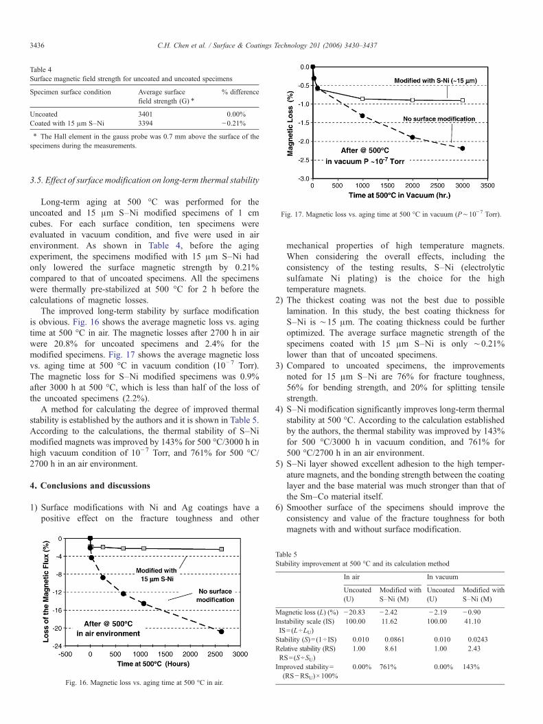
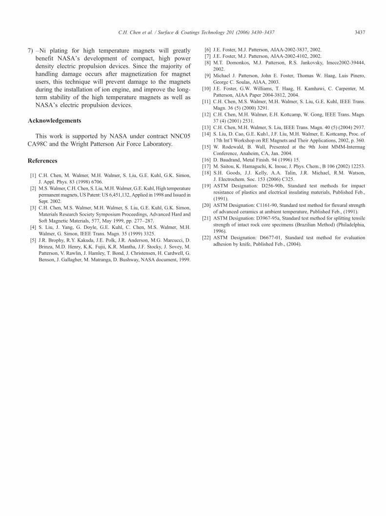
Fig. 17. Magnetic loss vs. aging time at 500 °C in vacuum (P∼10−7 Torr).
Table 4Surface magnetic field strength for uncoated and uncoated specimens
Specimen surface condition Average surfacefield strength (G) ⁎
% difference
Uncoated 3401 0.00%Coated with 15 μm S–Ni 3394 −0.21%⁎ The Hall element in the gauss probe was 0.7 mm above the surface of thespecimens during the measurements.
3436 C.H. Chen et al. / Surface & Coatings Technology 201 (2006) 3430–3437
3.5. Effect of surface modification on long-term thermal stability
Long-term aging at 500 °C was performed for theuncoated and 15 μm S–Ni modified specimens of 1 cmcubes. For each surface condition, ten specimens wereevaluated in vacuum condition, and five were used in airenvironment. As shown in Table 4, before the agingexperiment, the specimens modified with 15 μm S–Ni hadonly lowered the surface magnetic strength by 0.21%compared to that of uncoated specimens. All the specimenswere thermally pre-stabilized at 500 °C for 2 h before thecalculations of magnetic losses.
The improved long-term stability by surface modificationis obvious. Fig. 16 shows the average magnetic loss vs. agingtime at 500 °C in air. The magnetic losses after 2700 h in airwere 20.8% for uncoated specimens and 2.4% for themodified specimens. Fig. 17 shows the average magnetic lossvs. aging time at 500 °C in vacuum condition (10−7 Torr).The magnetic loss for S–Ni modified specimens was 0.9%after 3000 h at 500 °C, which is less than half of the loss ofthe uncoated specimens (2.2%).
A method for calculating the degree of improved thermalstability is established by the authors and it is shown in Table 5.According to the calculations, the thermal stability of S–Nimodified magnets was improved by 143% for 500 °C/3000 h inhigh vacuum condition of 10−7 Torr, and 761% for 500 °C/2700 h in an air environment.
4. Conclusions and discussions
1) Surface modifications with Ni and Ag coatings have apositive effect on the fracture toughness and other
Fig. 16. Magnetic loss vs. aging time at 500 °C in air.
mechanical properties of high temperature magnets.When considering the overall effects, including theconsistency of the testing results, S–Ni (electrolyticsulfamate Ni plating) is the choice for the hightemperature magnets.
2) The thickest coating was not the best due to possiblelamination. In this study, the best coating thickness forS–Ni is ∼15 μm. The coating thickness could be furtheroptimized. The average surface magnetic strength of thespecimens coated with 15 μm S–Ni is only ∼0.21%lower than that of uncoated specimens.
3) Compared to uncoated specimens, the improvementsnoted for 15 μm S–Ni are 76% for fracture toughness,56% for bending strength, and 20% for splitting tensilestrength.
4) S–Ni modification significantly improves long-term thermalstability at 500 °C. According to the calculation establishedby the authors, the thermal stability was improved by 143%for 500 °C/3000 h in vacuum condition, and 761% for500 °C/2700 h in an air environment.
5) S–Ni layer showed excellent adhesion to the high temper-ature magnets, and the bonding strength between the coatinglayer and the base material was much stronger than that ofthe Sm–Co material itself.
6) Smoother surface of the specimens should improve theconsistency and value of the fracture toughness for bothmagnets with and without surface modification.
Table 5Stability improvement at 500 °C and its calculation method
In air In vacuum
Uncoated(U)
Modified withS–Ni (M)
Uncoated(U)
Modified withS–Ni (M)
Magnetic loss (L) (%) −20.83 −2.42 −2.19 −0.90Instability scale (IS) 100.00 11.62 100.00 41.10IS=(L÷LU)Stability (S)= (1÷IS) 0.010 0.0861 0.010 0.0243Relative stability (RS) 1.00 8.61 1.00 2.43RS=(S÷SU)Improved stability=(RS−RSU)×100%
0.00% 761% 0.00% 143%
3437C.H. Chen et al. / Surface & Coatings Technology 201 (2006) 3430–3437
7) –Ni plating for high temperature magnets will greatlybenefit NASA's development of compact, high powerdensity electric propulsion devices. Since the majority ofhandling damage occurs after magnetization for magnetusers, this technique will prevent damage to the magnetsduring the installation of ion engine, and improve the long-term stability of the high temperature magnets as well asNASA's electric propulsion devices.
Acknowledgements
This work is supported by NASA under contract NNC05CA98C and the Wright Patterson Air Force Laboratory.
References
[1] C.H. Chen, M. Walmer, M.H. Walmer, S. Liu, G.E. Kuhl, G.K. Simon,J. Appl. Phys. 83 (1998) 6706.
[2] M.S.Walmer, C.H. Chen, S. Liu,M.H.Walmer, G.E.Kuhl, High temperaturepermanent magnets, US Patent: US 6,451,132, Applied in 1998 and Issued inSept. 2002.
[3] C.H. Chen, M.S. Walmer, M.H. Walmer, S. Liu, G.E. Kuhl, G.K. Simon,Materials Research Society Symposium Proceedings, Advanced Hard andSoft Magnetic Materials, 577, May 1999, pp. 277–287.
[4] S. Liu, J. Yang, G. Doyle, G.E. Kuhl, C. Chen, M.S. Walmer, M.H.Walmer, G. Simon, IEEE Trans. Magn. 35 (1999) 3325.
[5] J.R. Brophy, R.Y. Kakuda, J.E. Polk, J.R. Anderson, M.G. Marcucci, D.Brinza, M.D. Henry, K.K. Fujii, K.R. Mantha, J.F. Stocky, J. Sovey, M.Patterson, V. Rawlin, J. Hamley, T. Bond, J. Christensen, H. Cardwell, G.Benson, J. Gallagher, M. Matranga, D. Bushway, NASA document, 1999.
[6] J.E. Foster, M.J. Patterson, AIAA-2002-3837, 2002.[7] J.E. Foster, M.J. Patterson, AIAA-2002-4102, 2002.[8] M.T. Domonkos, M.J. Patterson, R.S. Jankovsky, Imece2002-39444,
2002.[9] Michael J. Patterson, John E. Foster, Thomas W. Haag, Luis Pinero,
George C. Soulas, AIAA, 2003.[10] J.E. Foster, G.W. Williams, T. Haag, H. Kamhawi, C. Carpenter, M.
Patterson, AIAA Paper 2004-3812, 2004.[11] C.H. Chen, M.S. Walmer, M.H. Walmer, S. Liu, G.E. Kuhl, IEEE Trans.
Magn. 36 (5) (2000) 3291.[12] C.H. Chen, M.H. Walmer, E.H. Kottcamp, W. Gong, IEEE Trans. Magn.
37 (4) (2001) 2531.[13] C.H. Chen, M.H. Walmer, S. Liu, IEEE Trans. Magn. 40 (5) (2004) 2937.[14] S. Liu, D. Cao, G.E. Kuh1, J.F. Liu, M.H. Walmer, E. Kottcamp, Proc. of
17th Int'l Workshop on RE Magnets and Their Applications, 2002, p. 360.[15] W. Rodewald, B. Wall, Presented at the 9th Joint MMM-Intermag
Conference, Anaheim, CA, Jan. 2004.[16] D. Baudrand, Metal Finish. 94 (1996) 15.[17] M. Saitou, K. Hamaguchi, K. Inoue, J. Phys. Chem., B 106 (2002) 12253.[18] S.H. Goods, J.J. Kelly, A.A. Talin, J.R. Michael, R.M. Watson,
J. Electrochem. Soc. 153 (2006) C325.[19] ASTM Designation: D256-90b, Standard test methods for impact
resistance of plastics and electrical insulating materials, Published Feb.,(1991).
[20] ASTM Designation: C1161-90, Standard test method for flexural strengthof advanced ceramics at ambient temperature, Published Feb., (1991).
[21] ASTM Designation: D3967-95a, Standard test method for splitting tensilestrength of intact rock core specimens (Brazilian Method) (Philadelphia,1996).
[22] ASTM Designation: D6677-01, Standard test method for evaluationadhesion by knife, Published Feb., (2004).