Embed Size (px)
Citation preview

Effect of Small Addition of Zinc on Creep Behavior of Tin
Naoyuki Hamada1, Masakazu Hamada1, Tokuteru Uesugi2,Yorinobu Takigawa2 and Kenji Higashi2
1Ishikawa Metal Co., Ltd., Sakai 592-8352, Japan2Department of Materials Science, Graduate School of Engineering, Osaka Prefecture University, Sakai 599-8531, Japan
Sn-based alloys with high creep resistance are required for soldering applications. This paper describes the effect of solid solutionstrengthening on the creep resistance of Sn-Zn alloys. The maximum solubility limit of Zn is 0.34mass% in Sn. The creep behaviors of Sn, Sn-0.1mass%Zn and Sn-0.4mass%Zn were examined at 298 and 398K under constant strain rates ranging from 1� 10�4 to 1� 10�2 s�1. Thecreep resistance of Sn was improved significantly by the addition of a small amount of Zn owing to the solid solution strengthening. The creepresistance of Sn-0.4mass%Zn was at the same level as that of Sn-37mass%Pb. We obtained a stress exponent of about 7 and an activationenergy of 41–45 kJ/mol, which indicates that the creep behavior was climb-controlled dislocation creep controlled by pipe diffusion. The findingthat a small addition of Zn improves the creep resistance is useful for developing new Pb-free solders. [doi:10.2320/matertrans.MJ201023]
(Received June 14, 2010; Accepted August 2, 2010; Published September 15, 2010)
Keywords: lead-free solder, tin-zinc alloys, creep resistance, solid solution strengthening, stacking fault energy
1. Introduction
Eutectic Sn-37Pb solder has been the most widely usedmaterial for interconnecting and packaging electronic com-ponents. However, Pb and Pb-containing compounds areconsidered as toxic substances. Due to the current awarenessof the environmental and the health hazards associated withPb, many studies on Pb-free solders and soldering techniqueshave been performed with the aim of replacing Sn-Pb solderswith Pb-free alternatives.1,2) Considering performance, reli-ability and resources, Sn-Ag and Sn-Zn alloys have receivedthe most attention.3)
Eutectic Sn-9Zn alloy has a melting point of 471K, whichis closer to the 456K of eutectic Sn-37Pb than the 494K ofeutectic Sn-3.5Ag.4) Therefore, Sn-9Zn has been considereda potential Pb-free solder material.5,6) Many investigationshave dealt with different aspects of Sn-9Zn, such as itsmechanical properties,7) solderability8) and oxidation behav-ior.7) To apply a soldering material to a wide range ofapplications, high creep resistance is also required.9) Oneexample is dimensionally stable solder for optoelectronicapplications.10) The creep resistance of Sn-9Zn is superior tothat of Sn-37Pb.11) However, the general conclusion is thatdespite its better mechanical properties, Sn-9Zn has poorwettability to the Cu substrate, a phenomenon generallyrelated to the oxidation sensitivity of Zn.12,13) To improve thewettability, it is very effective to use hypoeutectic Sn-Znalloys having lower contents of Zn.14) Based on thisconsideration, Mahmudi et al. have researched the creepbehaviors of a series of Sn-Zn alloys (2.5–9mass%Zn) andfound that creep resistance was due to the higher volumefraction of Zn-rich second phase particles in the moreconcentrated alloys.14)
In Sn-Zn alloys, trace Zn is soluble in the Sn matrix, whichhas a maximum solubility limit of 0.34mass%Zn.15) In thiswork, the objective was to clarify the effect of solid solutionstrengthening on the creep resistance of Sn-Zn alloys bymeans of a constant strain rate tensile test. We believe thatthe findings presented in this paper will be useful for thedevelopment of new creep-resistant Pb-free solders.
2. Experimental Procedure
Sn, Sn-0.1mass%Zn and Sn-0.4mass%Zn were used in thisstudy. For the preparation of these alloys, high-purity Sn(99.98% purity, Yunnan Chengfeng Non-ferrous Metals Co.,Ltd., China) and Zn (99.9% purity, Mitsuwa Chemicals Co.,Ltd., Japan) were used as starting materials. The chemicalcompositions are shown in Table 1. The alloys were initiallyproduced by ingot casting. The casting temperature was603K, which was about 100K above the liquidus linetemperature.15) The molten alloys were cast into an ironmold. The inner diameter and length of the mold were 30 and140mm, respectively. The ingots were solution-treated for24 h in air and then water-quenched. The solution-treatmenttemperatures were 423K for Sn and 453K for Sn-0.1Zn andSn-0.4Zn. The ingots were then extruded into cylindrical barsof 12mm in diameter at an extrusion temperature of 373K.The cylindrical bars were machined as tensile test specimenswith a gage length of 12mm and a diameter of 4mm. Tensiletests were carried out by the constant strain rate method atstrain rates ranging from 1� 10�4 to 1� 10�2 s�1 and at tem-peratures of 298K (¼ 0:59 Tm, where Tm is the melting pointof Sn, Sn-0.1Zn and Sn-0.4Zn15)) and 398K (¼ 0:79 Tm).
The microstructures were examined by means of ascanning electron microscope (SEM). The microstructuresafter the extrusion are shown in Figs. 1(a) for Sn, 1(b) forSn-0.1Zn and 1(c) for Sn-0.4Zn. The average grain sizeswere 5.8, 5.0 and 4.2 mm for Sn, Sn-0.1Zn and Sn-0.4Zn,respectively. It will be shown that the amount of Zn insolution is the important variable in explaining the creepresistance of Sn-Zn alloys in the latter. A Sn-Zn eutectic
Table 1 Chemical compositions for Sn, Sn-0.1Zn and Sn-0.4Zn (mass%).
Sn Zn Sb Cu Bi Pb Fe In
Sn balance 0.001 0.001 0.001 0.001 0.002 0.002 0.003
Sn-0.1Zn balance 0.10 0.001 0.001 0.002 0.002 0.002 0.003
Sn-0.4Zn balance 0.41 0.001 0.001 0.001 0.001 0.002 0.003
Materials Transactions, Vol. 51, No. 10 (2010) pp. 1747 to 1752Special Issue on Lead-Free and Advanced Interconnection Materials for Electronics#2010 The Japan Institute of Metals
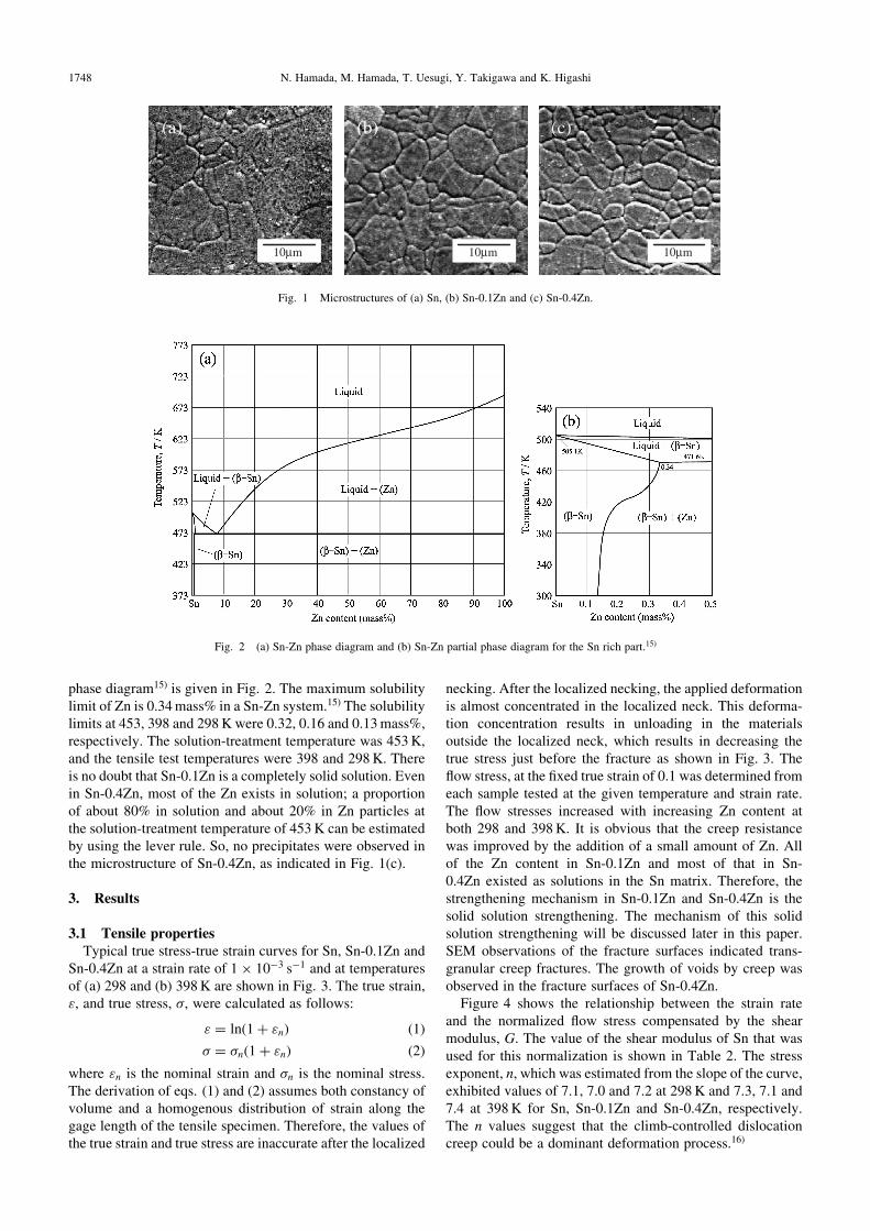
phase diagram15) is given in Fig. 2. The maximum solubilitylimit of Zn is 0.34mass% in a Sn-Zn system.15) The solubilitylimits at 453, 398 and 298K were 0.32, 0.16 and 0.13mass%,respectively. The solution-treatment temperature was 453K,and the tensile test temperatures were 398 and 298K. Thereis no doubt that Sn-0.1Zn is a completely solid solution. Evenin Sn-0.4Zn, most of the Zn exists in solution; a proportionof about 80% in solution and about 20% in Zn particles atthe solution-treatment temperature of 453K can be estimatedby using the lever rule. So, no precipitates were observed inthe microstructure of Sn-0.4Zn, as indicated in Fig. 1(c).
3. Results
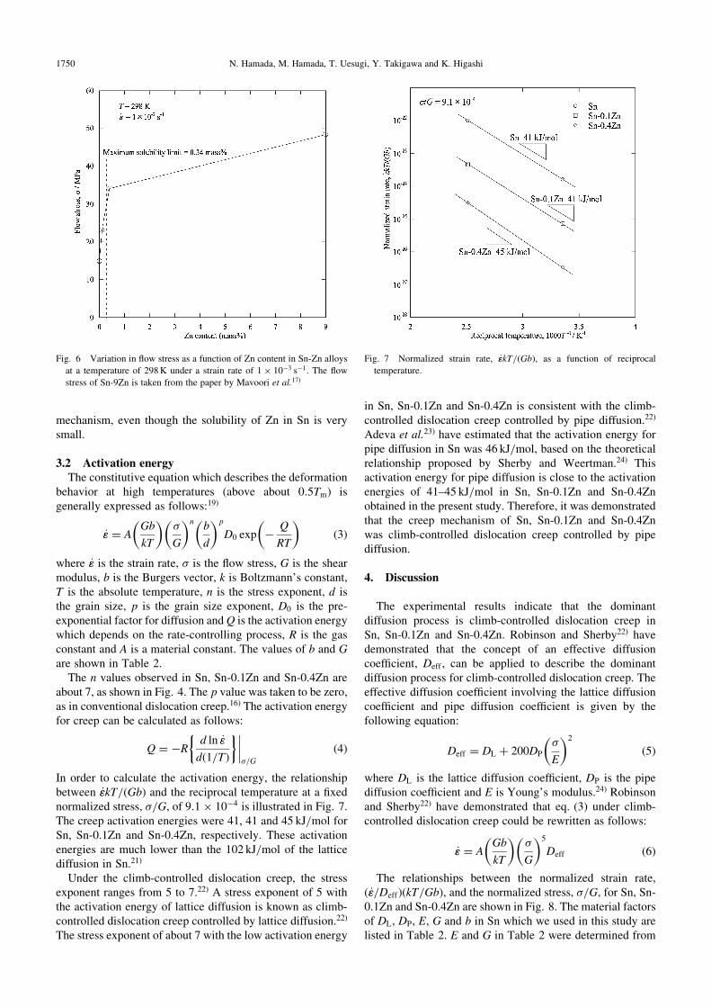
3.1 Tensile propertiesTypical true stress-true strain curves for Sn, Sn-0.1Zn and
Sn-0.4Zn at a strain rate of 1� 10�3 s�1 and at temperaturesof (a) 298 and (b) 398K are shown in Fig. 3. The true strain,", and true stress, �, were calculated as follows:
" ¼ lnð1þ "nÞ ð1Þ� ¼ �nð1þ "nÞ ð2Þ
where "n is the nominal strain and �n is the nominal stress.The derivation of eqs. (1) and (2) assumes both constancy ofvolume and a homogenous distribution of strain along thegage length of the tensile specimen. Therefore, the values ofthe true strain and true stress are inaccurate after the localized
necking. After the localized necking, the applied deformationis almost concentrated in the localized neck. This deforma-tion concentration results in unloading in the materialsoutside the localized neck, which results in decreasing thetrue stress just before the fracture as shown in Fig. 3. Theflow stress, at the fixed true strain of 0.1 was determined fromeach sample tested at the given temperature and strain rate.The flow stresses increased with increasing Zn content atboth 298 and 398K. It is obvious that the creep resistancewas improved by the addition of a small amount of Zn. Allof the Zn content in Sn-0.1Zn and most of that in Sn-0.4Zn existed as solutions in the Sn matrix. Therefore, thestrengthening mechanism in Sn-0.1Zn and Sn-0.4Zn is thesolid solution strengthening. The mechanism of this solidsolution strengthening will be discussed later in this paper.SEM observations of the fracture surfaces indicated trans-granular creep fractures. The growth of voids by creep wasobserved in the fracture surfaces of Sn-0.4Zn.
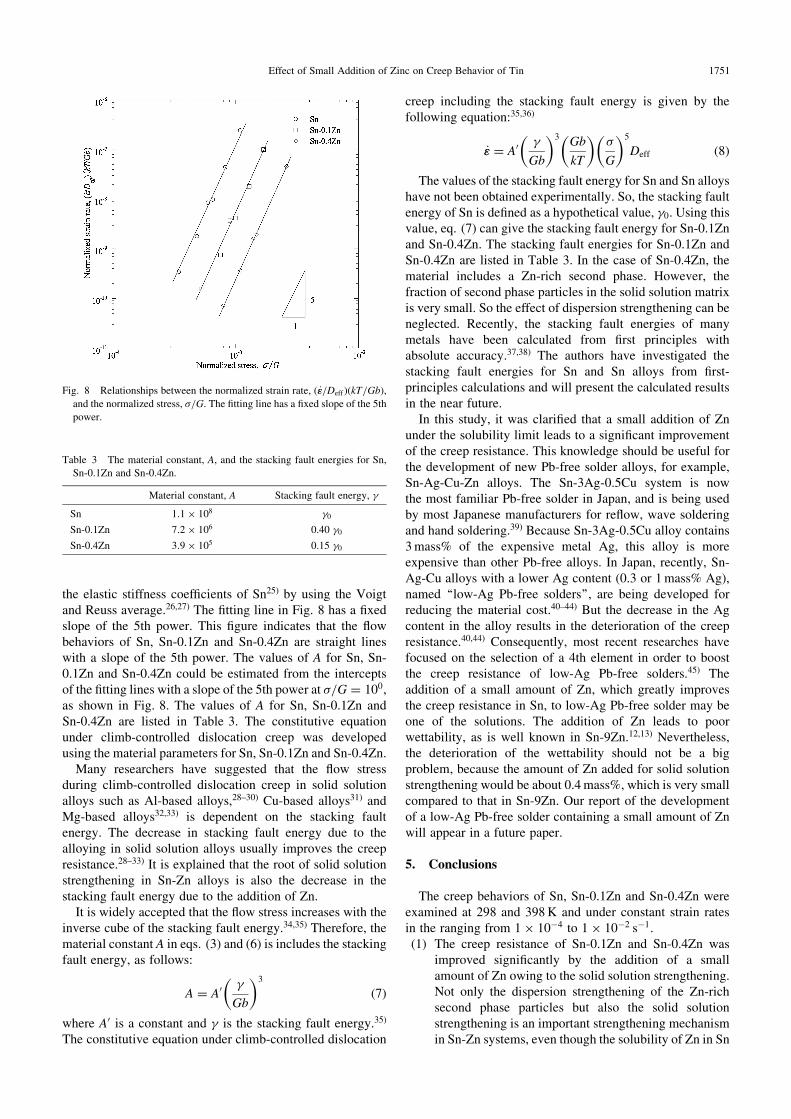
Figure 4 shows the relationship between the strain rateand the normalized flow stress compensated by the shearmodulus, G. The value of the shear modulus of Sn that wasused for this normalization is shown in Table 2. The stressexponent, n, which was estimated from the slope of the curve,exhibited values of 7.1, 7.0 and 7.2 at 298K and 7.3, 7.1 and7.4 at 398K for Sn, Sn-0.1Zn and Sn-0.4Zn, respectively.The n values suggest that the climb-controlled dislocationcreep could be a dominant deformation process.16)
(b)
10µm
(a) (c)
10µm 10µm
Fig. 1 Microstructures of (a) Sn, (b) Sn-0.1Zn and (c) Sn-0.4Zn.
Fig. 2 (a) Sn-Zn phase diagram and (b) Sn-Zn partial phase diagram for the Sn rich part.15)
1748 N. Hamada, M. Hamada, T. Uesugi, Y. Takigawa and K. Higashi
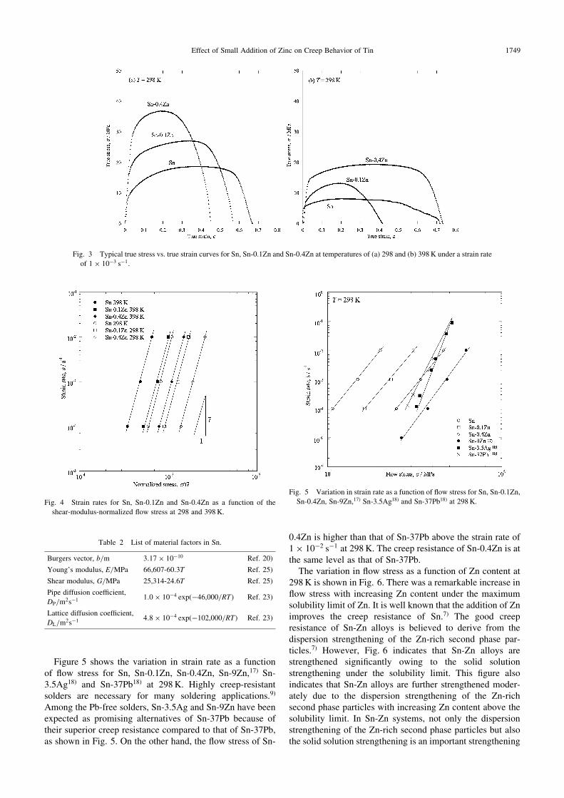
Figure 5 shows the variation in strain rate as a functionof flow stress for Sn, Sn-0.1Zn, Sn-0.4Zn, Sn-9Zn,17) Sn-3.5Ag18) and Sn-37Pb18) at 298K. Highly creep-resistantsolders are necessary for many soldering applications.9)
Among the Pb-free solders, Sn-3.5Ag and Sn-9Zn have beenexpected as promising alternatives of Sn-37Pb because oftheir superior creep resistance compared to that of Sn-37Pb,as shown in Fig. 5. On the other hand, the flow stress of Sn-
0.4Zn is higher than that of Sn-37Pb above the strain rate of1� 10�2 s�1 at 298K. The creep resistance of Sn-0.4Zn is atthe same level as that of Sn-37Pb.
The variation in flow stress as a function of Zn content at298K is shown in Fig. 6. There was a remarkable increase inflow stress with increasing Zn content under the maximumsolubility limit of Zn. It is well known that the addition of Znimproves the creep resistance of Sn.7) The good creepresistance of Sn-Zn alloys is believed to derive from thedispersion strengthening of the Zn-rich second phase par-ticles.7) However, Fig. 6 indicates that Sn-Zn alloys arestrengthened significantly owing to the solid solutionstrengthening under the solubility limit. This figure alsoindicates that Sn-Zn alloys are further strengthened moder-ately due to the dispersion strengthening of the Zn-richsecond phase particles with increasing Zn content above thesolubility limit. In Sn-Zn systems, not only the dispersionstrengthening of the Zn-rich second phase particles but alsothe solid solution strengthening is an important strengthening
Fig. 3 Typical true stress vs. true strain curves for Sn, Sn-0.1Zn and Sn-0.4Zn at temperatures of (a) 298 and (b) 398K under a strain rate
of 1� 10�3 s�1.
Fig. 4 Strain rates for Sn, Sn-0.1Zn and Sn-0.4Zn as a function of the
shear-modulus-normalized flow stress at 298 and 398K.
Table 2 List of material factors in Sn.
Burgers vector, b/m 3:17� 10�10 Ref. 20)
Young’s modulus, E/MPa 66;607-60:3T Ref. 25)
Shear modulus, G/MPa 25;314-24:6T Ref. 25)
Pipe diffusion coefficient,
DP/m2s�1 1:0� 10�4 expð�46;000=RTÞ Ref. 23)
Lattice diffusion coefficient,
DL/m2s�1 4:8� 10�4 expð�102;000=RTÞ Ref. 23)
Fig. 5 Variation in strain rate as a function of flow stress for Sn, Sn-0.1Zn,
Sn-0.4Zn, Sn-9Zn,17) Sn-3.5Ag18) and Sn-37Pb18) at 298K.
Effect of Small Addition of Zinc on Creep Behavior of Tin 1749
mechanism, even though the solubility of Zn in Sn is verysmall.
3.2 Activation energyThe constitutive equation which describes the deformation
behavior at high temperatures (above about 0:5Tm) isgenerally expressed as follows:19)
_"" ¼ AGb
kT
� ��
G
� �n b
d
� �p
D0 exp �Q
RT
� �ð3Þ
where _"" is the strain rate, � is the flow stress, G is the shearmodulus, b is the Burgers vector, k is Boltzmann’s constant,T is the absolute temperature, n is the stress exponent, d isthe grain size, p is the grain size exponent, D0 is the pre-exponential factor for diffusion andQ is the activation energywhich depends on the rate-controlling process, R is the gasconstant and A is a material constant. The values of b and G
are shown in Table 2.The n values observed in Sn, Sn-0.1Zn and Sn-0.4Zn are
about 7, as shown in Fig. 4. The p value was taken to be zero,as in conventional dislocation creep.16) The activation energyfor creep can be calculated as follows:
Q ¼ �Rd ln _""
dð1=TÞ
� ������=G
ð4Þ
In order to calculate the activation energy, the relationshipbetween _""kT=ðGbÞ and the reciprocal temperature at a fixednormalized stress, �=G, of 9:1� 10�4 is illustrated in Fig. 7.The creep activation energies were 41, 41 and 45 kJ/mol forSn, Sn-0.1Zn and Sn-0.4Zn, respectively. These activationenergies are much lower than the 102 kJ/mol of the latticediffusion in Sn.21)
Under the climb-controlled dislocation creep, the stressexponent ranges from 5 to 7.22) A stress exponent of 5 withthe activation energy of lattice diffusion is known as climb-controlled dislocation creep controlled by lattice diffusion.22)
The stress exponent of about 7 with the low activation energy
in Sn, Sn-0.1Zn and Sn-0.4Zn is consistent with the climb-controlled dislocation creep controlled by pipe diffusion.22)
Adeva et al.23) have estimated that the activation energy forpipe diffusion in Sn was 46 kJ/mol, based on the theoreticalrelationship proposed by Sherby and Weertman.24) Thisactivation energy for pipe diffusion is close to the activationenergies of 41–45 kJ/mol in Sn, Sn-0.1Zn and Sn-0.4Znobtained in the present study. Therefore, it was demonstratedthat the creep mechanism of Sn, Sn-0.1Zn and Sn-0.4Znwas climb-controlled dislocation creep controlled by pipediffusion.
4. Discussion
The experimental results indicate that the dominantdiffusion process is climb-controlled dislocation creep inSn, Sn-0.1Zn and Sn-0.4Zn. Robinson and Sherby22) havedemonstrated that the concept of an effective diffusioncoefficient, Deff , can be applied to describe the dominantdiffusion process for climb-controlled dislocation creep. Theeffective diffusion coefficient involving the lattice diffusioncoefficient and pipe diffusion coefficient is given by thefollowing equation:
Deff ¼ DL þ 200DP
�
E
� �2
ð5Þ
where DL is the lattice diffusion coefficient, DP is the pipediffusion coefficient and E is Young’s modulus.24) Robinsonand Sherby22) have demonstrated that eq. (3) under climb-controlled dislocation creep could be rewritten as follows:
_"" ¼ AGb
kT
� ��
G
� �5
Deff ð6Þ
The relationships between the normalized strain rate,ð _""=DeffÞðkT=GbÞ, and the normalized stress, �=G, for Sn, Sn-0.1Zn and Sn-0.4Zn are shown in Fig. 8. The material factorsof DL, DP, E, G and b in Sn which we used in this study arelisted in Table 2. E and G in Table 2 were determined from
Fig. 6 Variation in flow stress as a function of Zn content in Sn-Zn alloys
at a temperature of 298K under a strain rate of 1� 10�3 s�1. The flow
stress of Sn-9Zn is taken from the paper by Mavoori et al.17)
Fig. 7 Normalized strain rate, _""kT=ðGbÞ, as a function of reciprocal
temperature.
1750 N. Hamada, M. Hamada, T. Uesugi, Y. Takigawa and K. Higashi
the elastic stiffness coefficients of Sn25) by using the Voigtand Reuss average.26,27) The fitting line in Fig. 8 has a fixedslope of the 5th power. This figure indicates that the flowbehaviors of Sn, Sn-0.1Zn and Sn-0.4Zn are straight lineswith a slope of the 5th power. The values of A for Sn, Sn-0.1Zn and Sn-0.4Zn could be estimated from the interceptsof the fitting lines with a slope of the 5th power at �=G ¼ 100,as shown in Fig. 8. The values of A for Sn, Sn-0.1Zn andSn-0.4Zn are listed in Table 3. The constitutive equationunder climb-controlled dislocation creep was developedusing the material parameters for Sn, Sn-0.1Zn and Sn-0.4Zn.
Many researchers have suggested that the flow stressduring climb-controlled dislocation creep in solid solutionalloys such as Al-based alloys,28–30) Cu-based alloys31) andMg-based alloys32,33) is dependent on the stacking faultenergy. The decrease in stacking fault energy due to thealloying in solid solution alloys usually improves the creepresistance.28–33) It is explained that the root of solid solutionstrengthening in Sn-Zn alloys is also the decrease in thestacking fault energy due to the addition of Zn.
It is widely accepted that the flow stress increases with theinverse cube of the stacking fault energy.34,35) Therefore, thematerial constant A in eqs. (3) and (6) is includes the stackingfault energy, as follows:
A ¼ A0 �
Gb
� �3
ð7Þ
where A0 is a constant and � is the stacking fault energy.35)
The constitutive equation under climb-controlled dislocation
creep including the stacking fault energy is given by thefollowing equation:35,36)
_"" ¼ A0 �
Gb
� �3 Gb
kT
� ��
G
� �5
Deff ð8Þ
The values of the stacking fault energy for Sn and Sn alloyshave not been obtained experimentally. So, the stacking faultenergy of Sn is defined as a hypothetical value, �0. Using thisvalue, eq. (7) can give the stacking fault energy for Sn-0.1Znand Sn-0.4Zn. The stacking fault energies for Sn-0.1Zn andSn-0.4Zn are listed in Table 3. In the case of Sn-0.4Zn, thematerial includes a Zn-rich second phase. However, thefraction of second phase particles in the solid solution matrixis very small. So the effect of dispersion strengthening can beneglected. Recently, the stacking fault energies of manymetals have been calculated from first principles withabsolute accuracy.37,38) The authors have investigated thestacking fault energies for Sn and Sn alloys from first-principles calculations and will present the calculated resultsin the near future.
In this study, it was clarified that a small addition of Znunder the solubility limit leads to a significant improvementof the creep resistance. This knowledge should be useful forthe development of new Pb-free solder alloys, for example,Sn-Ag-Cu-Zn alloys. The Sn-3Ag-0.5Cu system is nowthe most familiar Pb-free solder in Japan, and is being usedby most Japanese manufacturers for reflow, wave solderingand hand soldering.39) Because Sn-3Ag-0.5Cu alloy contains3mass% of the expensive metal Ag, this alloy is moreexpensive than other Pb-free alloys. In Japan, recently, Sn-Ag-Cu alloys with a lower Ag content (0.3 or 1mass% Ag),named ‘‘low-Ag Pb-free solders’’, are being developed forreducing the material cost.40–44) But the decrease in the Agcontent in the alloy results in the deterioration of the creepresistance.40,44) Consequently, most recent researches havefocused on the selection of a 4th element in order to boostthe creep resistance of low-Ag Pb-free solders.45) Theaddition of a small amount of Zn, which greatly improvesthe creep resistance in Sn, to low-Ag Pb-free solder may beone of the solutions. The addition of Zn leads to poorwettability, as is well known in Sn-9Zn.12,13) Nevertheless,the deterioration of the wettability should not be a bigproblem, because the amount of Zn added for solid solutionstrengthening would be about 0.4mass%, which is very smallcompared to that in Sn-9Zn. Our report of the developmentof a low-Ag Pb-free solder containing a small amount of Znwill appear in a future paper.
5. Conclusions
The creep behaviors of Sn, Sn-0.1Zn and Sn-0.4Zn wereexamined at 298 and 398K and under constant strain ratesin the ranging from 1� 10�4 to 1� 10�2 s�1.(1) The creep resistance of Sn-0.1Zn and Sn-0.4Zn was
improved significantly by the addition of a smallamount of Zn owing to the solid solution strengthening.Not only the dispersion strengthening of the Zn-richsecond phase particles but also the solid solutionstrengthening is an important strengthening mechanismin Sn-Zn systems, even though the solubility of Zn in Sn
Fig. 8 Relationships between the normalized strain rate, ð _""=DeffÞðkT=GbÞ,and the normalized stress, �=G. The fitting line has a fixed slope of the 5thpower.
Table 3 The material constant, A, and the stacking fault energies for Sn,
Sn-0.1Zn and Sn-0.4Zn.
Material constant, A Stacking fault energy, �
Sn 1:1� 108 �0
Sn-0.1Zn 7:2� 106 0.40 �0
Sn-0.4Zn 3:9� 105 0.15 �0
Effect of Small Addition of Zinc on Creep Behavior of Tin 1751
is very small: the maximum solubility limit is 0.34mass%Zn.
(2) A stress exponent of about 7 and an activation energyof 41–45 kJ/mol were obtained for Sn, Sn-0.1Zn andSn-0.4Zn. This activation energy was close to the46 kJ/mol for pipe diffusion in Sn. This, together withthe stress exponent of about 7, suggests that the creepbehavior of Sn, Sn-0.1Zn and Sn-0.4Zn was climb-controlled dislocation creep controlled by pipe diffu-sion. The creep mechanism controlled by dislocationclimb demonstrated that the root of the solid solutionstrengthening in the Sn-Zn system is the decrease inthe stacking fault energy due to the addition of Zn. Theconstitutive equation under climb-controlled disloca-tion creep was developed using the material parametersfor Sn, Sn-0.1Zn and Sn-0.4Zn.
Acknowledgements
The authors would like to thank Dr. T. Hirata and Dr.T. Tanaka of the Technology Research Institute of OsakaPrefecture for their useful discussions and comments. Thisresearch was partly supported by Potentiality VerificationStage of Collaborative Development of Innovative Seeds,Japan Science and Technology Agency (JST).
REFERENCES
1) K. Suganuma: Curr. Opini. Solid State Mater. Sci. 5 (2001) 55–64.
2) S. K. Kang: J. Electron. Mater. 8 (1994) 701–707.
3) X. Chen, M. Li, X. X. Ren, A. M. Hu and D. L. Mao: J. Electron. Mater.
35 (2006) 1734–1739.
4) W. J. Plumbridge: Mater. High Temp. 17 (2000) 381–387.
5) M. McCormack, S. Jin and H. S. Chen: J. Electron. Mater. 23 (1994)
687–690.
6) R. A. Islam, B. Y. Wu, M. O. Alam, Y. C. Chan and W. Jillek: J. Alloy.
Compd. 392 (2005) 149–158.
7) R. Mahmudi, A. R. Geranmayeh and A. Rezaee-Bazzaz: Mater. Sci.
Eng. A 448 (2007) 287–293.
8) J. E. Lee, K. S. Kim, M. Inoue, J. Jiang and K. Suganuma: J. Alloy.
Compd. 454 (2008) 310–320.
9) R. J. Mccabe and M. E. Fine: J. Electron. Mater. 31 (2002) 1276–1282.
10) H. Mavoori and S. Jin: JOM 52 (2000) 30–32.
11) R. Mahmudi, A. R. Geranmayeh, H. Khanbareh and N. Jahangiri:
Mater. Design 30 (2009) 574–580.
12) K. I. Chen, S. C. Cheng, S. Wu and K. L. Lin: J. Alloy. Compd. 416
(2006) 98–105.
13) S. Vaynman and M. E. Fine: Scr. Mater. 41 (1999) 1269–1271.
14) R. Maumudi, A. R. Geranmayeh, H. Noori and M. Shahabi: Mater. Sci.
Eng. A 491 (2008) 110–116.
15) Z. Moser, J. Dutkiewicz, W. Gasior and J. Salawa: Bull. Alloy Phase
Diagrams 6 (1985) 330.
16) D. Sherby and J. Wadsworth: Prog. Mater. Sci. 33 (1989) 169–221.
17) H. Mavoori, J. Chin, S. Vaynman, B. Moran, L. Keer and M. Fine:
J. Electron. Mater. 26 (1997) 783–790.
18) I. Shohji, T. Yoshida, T. Takahashi and S. Hioki: Mater. Sci. Eng. A
366 (2004) 50–55.
19) R. S. Mishra, T. R. Bieler and A. K. Mukherjee: Acta Mater. 43 (1995)
877–891.
20) M. Fujiwara and T. Hirokawa: J. Japan Inst. Metals 51 (1987) 830–838.
21) J. D. Meakin and E. Klokholm: Trans. Metall. AIME 218 (1960) 463–
466.
22) S. L. Robinson and O. D. Sherby: Acta Mater. 18 (1969) 109–125.
23) P. Adeva, G. Caruana, O. A. Ruano and M. Torralba: Mater. Sci. Eng.
A 194 (1995) 17–23.
24) D. Sherby and J. Weertman: Acta Metall. 27 (1979) 387–400.
25) J. A. Rayne and B. S. Chandrasekhar: Phys. Rev. 120 (1960) 1658–
1663.
26) R. Hill: Proc. Phys. Soc. London Sect. A 65 (1952) 349–354.
27) T. Uesugi, Y. Takigawa and K. Higashi: Mater. Trans. 46 (2005) 1117–
1121.
28) M. S. Soliman: Mater. Sci. Eng. A 201 (1995) 111–117.
29) P. K. Chaudhury and F. A. Mohamed: Metall. Trans. A 18 (1987)
2105–2114.
30) E. M. Taleff, G. A. Henshall, T. G. Nieh, D. R. Lesuer and J.
Wadsworth: Metall. Mater. Trans. A 29 (1988) 1081–1091.
31) R. M. Bonesteel and O. D. Sherby: Acta Mater. 14 (1966) 385–390.
32) H. Somekawa, K. Hirai, H. Watanabe, Y. Takigawa and K. Higashi:
Mater. Sci. Eng. A 407 (2005) 53–61.
33) S. W. Chung, H. Watanabe,W. J. Kim and K. Higashi: Mater. Trans. 45
(2004) 1266–1271.
34) M. S. Soliman: J. Mater. Sci. 28 (1993) 4483–4488.
35) S. S. Vagarali and T. G. Langdon: Acta Metall. 30 (1982) 1157–1170.
36) S. S. Vagarali and T. G. Langdon: Acta Metall. 29 (1981) 1969–1982.
37) N. Bernstein and E. B. Tadmor: Phys. Rev. B 69 (2004) 94–116.
38) T. Uesugi, M. Kohyama, M. Kohzu and K. Higashi: Mater. Sci. Forum
419–422 (2003) 225–230.
39) K. S. Kim, S. H. Huh and K. Suganuma: Microelectron. Reliab. 43
(2003) 259–267.
40) T. Ohnishi: JEITA Lead-free Activities Report 2008, (Japan Elec-
tronics and Information Technology Industries Association, 2008)
pp. 121–140.
41) Y. Kariya, T. Hosoi, T. Kimura, S. Terashima and M. Tanaka: Mater.
Trans. 45 (2004) 689–694.
42) S. Terashima, Y. Kariya, T. Hosoi and M. Tanaka: J. Electron. Mater.
32 (2003) 1527–1533.
43) S. Terashima, Y. Kariya and M. Tanaka: Mater. Trans. 45 (2004) 673–
680.
44) T. Chen and I. Dutta: J. Electron. Mater. 37 (2008) 347–354.
45) T. Ohnishi and T. Moribayashi: JEITA Lead-free Activities Report
2007, (Japan Electronics and Information Technology Industries
Association, 2007) pp. 133–146.
1752 N. Hamada, M. Hamada, T. Uesugi, Y. Takigawa and K. Higashi