Embed Size (px)
Citation preview
Erwin V. ZaretskyGlenn Research Center, Cleveland, Ohio
Brian L. VlcekGeorgia Southern University, Statesboro, Georgia
Robert C. HendricksGlenn Research Center, Cleveland, Ohio
Effect of Silicon Nitride Balls and Rollerson Rolling Bearing Life
NASA/TM—2005-213061
April 2005
TRIB2004–64246
https://ntrs.nasa.gov/search.jsp?R=20050175860 2018-08-20T16:46:31+00:00Z
The NASA STI Program Office . . . in Profile
Since its founding, NASA has been dedicated tothe advancement of aeronautics and spacescience. The NASA Scientific and TechnicalInformation (STI) Program Office plays a key partin helping NASA maintain this important role.
The NASA STI Program Office is operated byLangley Research Center, the Lead Center forNASA’s scientific and technical information. TheNASA STI Program Office provides access to theNASA STI Database, the largest collection ofaeronautical and space science STI in the world.The Program Office is also NASA’s institutionalmechanism for disseminating the results of itsresearch and development activities. These resultsare published by NASA in the NASA STI ReportSeries, which includes the following report types:
• TECHNICAL PUBLICATION. Reports ofcompleted research or a major significantphase of research that present the results ofNASA programs and include extensive dataor theoretical analysis. Includes compilationsof significant scientific and technical data andinformation deemed to be of continuingreference value. NASA’s counterpart of peer-reviewed formal professional papers buthas less stringent limitations on manuscriptlength and extent of graphic presentations.
• TECHNICAL MEMORANDUM. Scientificand technical findings that are preliminary orof specialized interest, e.g., quick releasereports, working papers, and bibliographiesthat contain minimal annotation. Does notcontain extensive analysis.
• CONTRACTOR REPORT. Scientific andtechnical findings by NASA-sponsoredcontractors and grantees.
• CONFERENCE PUBLICATION. Collectedpapers from scientific and technicalconferences, symposia, seminars, or othermeetings sponsored or cosponsored byNASA.
• SPECIAL PUBLICATION. Scientific,technical, or historical information fromNASA programs, projects, and missions,often concerned with subjects havingsubstantial public interest.
• TECHNICAL TRANSLATION. English-language translations of foreign scientificand technical material pertinent to NASA’smission.
Specialized services that complement the STIProgram Office’s diverse offerings includecreating custom thesauri, building customizeddatabases, organizing and publishing researchresults . . . even providing videos.
For more information about the NASA STIProgram Office, see the following:
• Access the NASA STI Program Home Pageat http://www.sti.nasa.gov
• E-mail your question via the Internet [email protected]
• Fax your question to the NASA AccessHelp Desk at 301–621–0134
• Telephone the NASA Access Help Desk at301–621–0390
• Write to: NASA Access Help Desk NASA Center for AeroSpace Information 7121 Standard Drive Hanover, MD 21076
Erwin V. ZaretskyGlenn Research Center, Cleveland, Ohio
Brian L. VlcekGeorgia Southern University, Statesboro, Georgia
Robert C. HendricksGlenn Research Center, Cleveland, Ohio
Effect of Silicon Nitride Balls and Rollerson Rolling Bearing Life
NASA/TM—2005-213061
April 2005
National Aeronautics andSpace Administration
Glenn Research Center
Prepared for the2004 International Joint Tribology Conferencecosponsored by the American Society of Mechanical Engineersand the Society of Tribologists and Lubrication EngineersLong Beach, California, October 24–27, 2004
TRIB2004–64246

Available from
NASA Center for Aerospace Information7121 Standard DriveHanover, MD 21076
National Technical Information Service5285 Port Royal RoadSpringfield, VA 22100
Available electronically at http://gltrs.grc.nasa.gov
NASA/TM—2005-213061 1
Effect of Silicon Nitride Balls and Rollers on Rolling Bearing Life
Erwin V. Zaretsky National Aeronautics and Space Administration
Glenn Research Center Cleveland, Ohio 44135
Brian L. Vlcek
Georgia Southern University Statesboro, Georgia 30460
Robert C. Hendricks
National Aeronautics and Space Administration Glenn Research Center Cleveland, Ohio 44135
Summary
Three decades have passed since the introduction of silicon nitride rollers and balls into conventional rolling-element bearings. For a given applied load, the contact (Hertz) stress in a hybrid bearing will be higher than an all-steel rolling-element bearing. The silicon nitride rolling-element life as well as the lives of the steel races were used to determine the resultant bearing life of both hybrid and all-steel bearings. Life factors were determined and reported for hybrid bearings. Under nominal operating speeds, the resultant calculated lives of the deep-groove, angular-contact, and cylindrical roller hybrid bearings with races made of post-1960 bearing steel increased by factors of 3.7, 3.2, and 5.5, respectively, from those calculated using the Lundberg-Palmgren equations. An all-steel bearing under the same load will have a longer life than the equivalent hybrid bearing under the same conditions. Under these conditions, hybrid bearings are predicted to have a lower fatigue life than all-steel bearings by 58 percent for deep-groove bearings, 41 percent for angular-contact bearings, and 28 percent for cylindrical roller bearings.
Introduction In 1970, Dee (ref. 1) first proposed hot-pressed silicon nitride for rolling-element bearings as well as
for journal bearings. A review of the development of silicon nitride for rolling-element bearing application can be found in references 2 and 3. Rolling-element fatigue testing of hot-pressed silicon nitride has resulted in several seemingly contradictory results.
Poor life results were obtained in the limited tests reported by Scott et al. (refs. 4 and 5) in 1971 and 1973. The results reported by Baumgartner et al. (refs. 6 to 8) in 1973 showed the rolling-element fatigue life of hot-pressed silicon nitride to exceed that of a typical rolling-element bearing steel. Extrapolation of the experimental results of Parker and Zaretsky (ref. 9) to contact loads that result in stress levels typical of those in rolling-element bearing applications indicate that hot-pressed silicon nitride running against steel may be expected to yield fatigue lives comparable to or greater than those of bearing quality steel running against steel (ref. 10).
In an attempt to resolve these differences, concurrent with the work of Dee (ref. 1), Scott et al. (ref. 4) and (ref. 5), Baumgartner et al. (refs. 6 to 8), and Parker and Zaretsky (ref. 9), hybrid bearings comprising silicon nitride rolling-elements and steel races were manufactured and tested (refs. 6 to 7 and 11 to 16) as well as all ceramic bearings comprising silicon nitride rolling elements and rings (refs. 6, 17, and 18). From references 8, 9, and 18, the Hertz stress-life exponent n for silicon nitride ranged from 16 to
NASA/TM—2005-213061 2
16.2 with an average value of 16.1 (ref. 10). These values are much higher than those for steel, which range from 9 to 12.
Morrison et al. (ref. 20) tested four groups of hybrid 45-mm-bore angular-contact ball bearings having vacuum induction melted-vacuum arc melted (VIM–VAR) AISI M–50 steel races and silicon nitride balls. The bearings were tested at four thrust loads. The loads produced inner-race maximum Hertz stresses of 1.95, 2.0, 2.17, and 2.44 GPa (283, 290, 315, and 354 ksi), respectively. All of the failures for each thrust load were spalling of a silicon nitride ball. There were no failures of the steel raceways. The life and dynamic capacity of the hybrid bearing were less than the theoretical life and capacity of all-steel AISI M–50 steel ball bearings.
Morrison et al. (ref. 20) reported that the load-life exponent p for the hybrid bearings was 4.29 with 95 percent confidence limits of 3.16 and 5.42. Based upon a load-life exponent of 4.29, the Hertz stress-life exponent n for these ball bearings is approximately 13, which is solely a function of the failure of the silicon nitride balls. From the experimental data, the actual Hertz stress-life exponent n of this silicon nitride hybrid bearing was approximately 14. These values are not significantly less than those obtained in references 8, 9, and 19.
In 1986, Komeya and Kotani (ref. 21) concluded that “silicon nitride (hybrid bearings) retains a rolling life equivalent to or better than that of conventional bearing steel.” Subsequent work reported by Tanimoto and Ikeda (ref. 22) and Tanimoto, Kajihara and Yanai (ref. 23) concluded that the rolling-element fatigue life of silicon nitride was over two times that of bearing steel and that the life of hybrid bearings was five times that predicted. These results suggest significantly higher lives are obtained than those predicted for these hybrid bearings.
These apparent differences in the literature are not totally contradictory. For a given applied load the contact (Hertz) stress in a hybrid bearing containing silicon nitride rolling elements and steel races will be higher than in an all-steel rolling-element bearing where all the components are manufactured from hardened bearing steel. This is because the modulus of elasticity of the silicon nitride is approximately 1.5 times that of a typical bearing steel.
From the work reported by Zaretsky (refs. 10, 24, and 25) and the analysis in appendix A that examines the effect of the modulus of elasticity and Poisson’s ratio on contact stress (these are based upon the bearing life analysis of Lundberg and Palmgren (ref. 26), it was concluded that because of the higher modulus of elasticity, the life of a hybrid bearing will be less than that of an all-steel bearing of the same design and under the same load. The problem is that the Lundberg-Palmgren (ref. 26) life equation does not consider the life of the rolling elements independent of the race lives, nor does it consider differences in the modulus of elasticity or the Hertz stress-life exponent.
In view of the aforementioned, it is the objectives of the work reported herein to (a) account for the differences in material properties, including the Hertz stress-life exponents, between the rolling elements and races, (b) account for the lives of the rolling-element as well as the race to determine the resultant bearing life, and (c) theoretically compare the predicted lives of hybrid silicon nitride bearings both with that predicted for all-steel bearings and the actual lives reported in the literature.
Nomenclature a semi-major axis of contact ellipse, m (in.) b one-half line contact width, m (in.) CD dynamic load capacity, N (lbf) c stress-life exponent DN speed parameter, bearing bore in mm times bearing speed in rpm e Weibull slope h exponent K geometry-load constant
NASA/TM—2005-213061 3
L life, number of stress cycles or hr L10 10-percent life or life at which 90 percent of a population survives, number of stress cycles or hr Lβ characteristic life or life at which 63.2 percent of population fails, number of stress cycles or hr LF life factor lL race track length, m (in.) lt roller length, m (in.) N life, number of stress cycles n Hertz stress-life exponent ∆n difference in Hertz stress-life exponent n P load, N (lbf) Peq equivalent radial load, N (lbf) Po normal load, N (lbf) p load-life exponent R radius of body, m (in.) r Hertz contact area radius, m (in.) S probability of survival, fraction or percent Smax maximum Hertz stress, GPa (ksi) V stressed volume, m3 (in.3) x ratio of load-life exponent to stress-life exponent, p/n Y modulus of elasticity (Young’s modulus), GPa (ksi) Z depth below surface, m (in.) Zo depth to the maximum orthogonal shearing stress, m (in.) Z45 depth to the maximum shearing stress, m (in.) z exponent δ Poisson ratio υ elastic constant, GPa–1 (ksi–1) τo orthogonal shearing stress, GPa (ksi) τ45 maximum shearing stress, GPa (ksi) Subscripts a, b body a or b c ceramic H hybrid bearing ir inner race LP Lundberg-Palmgren or outer race re rolling elements S all-steel bearing s steel SN silicon nitride 52100 CVM AISI 52100 steel
NASA/TM—2005-213061 4
Bearing Life Analysis
Lundberg-Palmgren Equation In probabilistic life models, the bearing physical characteristics, applied load, operating profile, and
environment determine the probability of failure, assuming that the life is represented by a known probability function. Weibull (refs. 27 to 29) was the first to suggest a reasonable way to estimate material fracture strength with such a probability function. Based upon the work of Weibull (refs. 27 to 29), G. Lundberg and A. Palmgren (ref. 26) in 1947 showed that the probability of survival S could be expressed as a power function of the orthogonal shearing stress τo, life N, depth to the maximum orthogonal shear stress Zo, and stressed volume V. That is,
1ln ~e
co h
o
N VS Z
τ (1)
From equation (1) and for some constant S,
[ ]/ 1/
/1 1~⎛ ⎞ ⎛ ⎞= ⎜ ⎟ ⎜ ⎟
⎝ ⎠⎝ ⎠
c e eh e
oo
L N ZVτ
(2)
where for ball bearings,
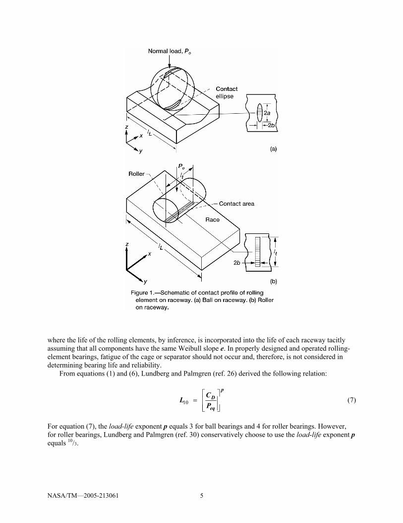
= L oV al Z (3)
and for roller bearings,
= t L oV l l Z (4) The resultant variables in equations (3) and (4) are defined in figure 1(a) and (b).
Lundberg and Palmgren (ref. 26) incorporated into their analysis a method and distribution function for statistically describing the fatigue life of materials developed by Weibull (ref. 27) referred to as the two-parameter Weibull distribution function:
1ln ln ln , where 0 ; 0 1⎛ ⎞= < < ∞ < <⎜ ⎟⎝ ⎠
Le L SS Lβ
(5)
From equation (5), Lundberg and Palmgren (ref. 26) first derived the relationship between individual component life and system life. A bearing is a system of multiple components, each with a different life. As a result, the life of the system is different from the life of an individual component in the system. The system life can be expressed to a first order as
10 10 10
1 1 1= +e e e
ir orL L L (6)
NASA/TM—2005-213061 5
where the life of the rolling elements, by inference, is incorporated into the life of each raceway tacitly assuming that all components have the same Weibull slope e. In properly designed and operated rolling-element bearings, fatigue of the cage or separator should not occur and, therefore, is not considered in determining bearing life and reliability.
From equations (1) and (6), Lundberg and Palmgren (ref. 26) derived the following relation:
10 ⎡ ⎤
= ⎢ ⎥⎢ ⎥⎣ ⎦
pD
eq
CL
P (7)
For equation (7), the load-life exponent p equals 3 for ball bearings and 4 for roller bearings. However, for roller bearings, Lundberg and Palmgren (ref. 30) conservatively choose to use the load-life exponent p equals 10/3.
NASA/TM—2005-213061 6
Zaretsky Equation The work of E.V. Zaretsky (ref. 31) builds upon the work of Weibull (ref. 27) and Lundberg and
Palmgren (ref. 26). Zaretsky eliminates the dependency of the stress-life relation on the Weibull slope e. The dependence of the depth to the critical shearing stress Z45 is reformulated. He also uses the maximum shear stress τ45 instead of the orthogonal shear stress τo as the critical shearing stress. equation (1) becomes
451ln ~ ce eN VS
τ (8)
For ball bearings, the stressed volume is
45= LV al Z (9a) and for roller bearings,
45= t LV l l Z (9b) From equation (8), the life of each bearing component can be derived where
1/
45
1 1~⎛ ⎞ ⎛ ⎞= ⎜ ⎟ ⎜ ⎟
⎝ ⎠⎝ ⎠
c eL N
Vτ (10)
Zaretsky’s Rule To apply Zaretsky’s rule (ref. 24), equation (6) should be written as follows:
10
1 1 1 1⎛ ⎞ ⎛ ⎞ ⎛ ⎞ ⎛ ⎞= + +⎜ ⎟ ⎜ ⎟ ⎜ ⎟ ⎜ ⎟
⎝ ⎠ ⎝ ⎠ ⎝ ⎠ ⎝ ⎠
e e e e
ir re orL L L L (11)
where the Weibull slope e is the same for each of the components as well as for the bearing as a system.
For radially loaded ball and roller bearings, the life of the rolling element set is equal to or greater than the life of the outer race. Let the life of the rolling element set (as a system) be equal to that of the outer race.
From equation (11)
10
1 1 12⎛ ⎞ ⎛ ⎞ ⎛ ⎞
= +⎜ ⎟ ⎜ ⎟ ⎜ ⎟⎝ ⎠ ⎝ ⎠ ⎝ ⎠
e e e
ir orL L L (12)
where Lre = Lor
For thrust loaded ball and roller bearings, the life of the rolling element set is equal to or greater than the life of the inner race but less than that of the outer race. Let the life of the rolling element set (as a system) be equal to that of the inner race.
From equation (11)
NASA/TM—2005-213061 7
10
1 1 12⎛ ⎞ ⎛ ⎞ ⎛ ⎞
= +⎜ ⎟ ⎜ ⎟ ⎜ ⎟⎝ ⎠ ⎝ ⎠ ⎝ ⎠
e e e
ir orL L L (13)
where Lre = Lir
Examples for using equations (11) to (13) are given in Zaretsky (ref. 24). As previously stated, the resulting values for Lir and Lor from these equations are not the same as those from equation (6). From the Zaretsky analysis, equation (7) remains unchanged. However, the values of the load-life exponent p become 4 and 5 for ball and roller bearings, respectively.
Effect of Elastic Constants
From the Hertz equations for stresses in concentrated contacts (ref. 32),
~ xmaxS P (14a)
where for ball bearings (point contact) with x = 1/3,
1 3~maxS P (14b) and for roller bearings (line contact) with x = 1/2,
1 2~maxS P (14c) From equations (7) and (14a),
1 1~ ~p nmax
LP S
(15a)
where
=pnx
(15b)
and the ratio of the load-life exponent p to the Hertz stress-life exponent n is
=pxn
(15c)
From equations (14b) and (15c), for point contact (ball bearings) n equals 9 when p equals 3, or
12 when p equals 4, and from equations (14c) and (15c), for line contact (roller bearings) when p equals 10/3, 4, or 5, then n equals 6.66, 8, and 10, respectively.
From appendix A, equation (A15), the life of a hybrid bearing having a steel raceway with a ceramic rolling element and the same normal load Po as a steel rolling element in contact with a steel raceway, the life of the hybrid bearing raceway is
NASA/TM—2005-213061 8
⎛ ⎞
= ⎜ ⎟⎜ ⎟⎝ ⎠
nmax S
H Smax H
SL L
S (16a)
Let:
= H
S
LLF
L (16b)
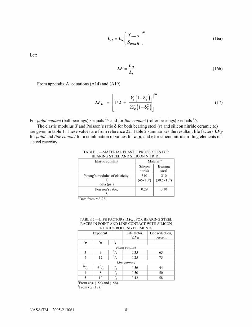
From appendix A, equations (A14) and (A19),
( )( )
2
2
1 1/ 2
2 1
⎡ ⎤−⎢ ⎥= +⎢ ⎥−⎢ ⎥⎣ ⎦
zns c
Hc s
YLF
Y
δ
δ (17)
For point contact (ball bearings) z equals 2/3 and for line contact (roller bearings) z equals 1/2.
The elastic modulus Y and Poisson’s ratio δ for both bearing steel (s) and silicon nitride ceramic (c) are given in table 1. These values are from reference 22. Table 2 summarizes the resultant life factors LFH for point and line contact for a combination of values for n, p, and z for silicon nitride rolling elements on a steel raceway.
TABLE 1.—MATERIAL ELASTIC PROPERTIES FOR
BEARING STEEL AND SILICON NITRIDE Materiala Elastic constant
Silicon nitride
Bearing steel
Young’s modulus of elasticity, Y,
GPa (psi)
310 (45×106)
210 (30.5×10⁶)
Poisson’s ratio, δ
0.29 0.30
aData from ref. 22.
TABLE 2.—LIFE FACTORS, LFH , FOR BEARING STEEL RACES IN POINT AND LINE CONTACT WITH SILICON
NITRIDE ROLLING ELEMENTS Exponent Life factor,
bLFH Life reduction,
percent ap an bz
Point contact 3 9 2/3 0.35 65 4 12 2/3 0.25 75
Line contact 10/3 6 2/3 1/2 0.56 44 4 8 1/2 0.50 50 5 10 1/2 0.42 58
aFrom eqs. (15a) and (15b). bFrom eq. (17).
NASA/TM—2005-213061 9
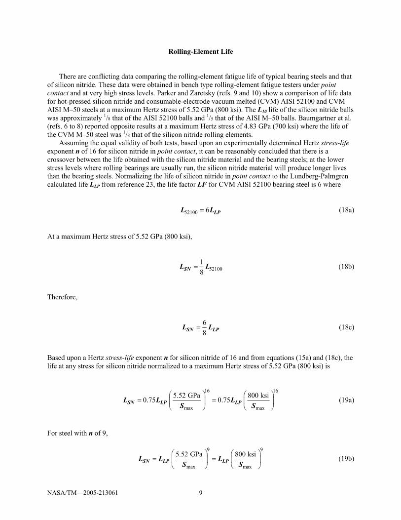
Rolling-Element Life There are conflicting data comparing the rolling-element fatigue life of typical bearing steels and that
of silicon nitride. These data were obtained in bench type rolling-element fatigue testers under point contact and at very high stress levels. Parker and Zaretsky (refs. 9 and 10) show a comparison of life data for hot-pressed silicon nitride and consumable-electrode vacuum melted (CVM) AISI 52100 and CVM AISI M–50 steels at a maximum Hertz stress of 5.52 GPa (800 ksi). The L10 life of the silicon nitride balls was approximately 1/8 that of the AISI 52100 balls and 1/5 that of the AISI M–50 balls. Baumgartner et al. (refs. 6 to 8) reported opposite results at a maximum Hertz stress of 4.83 GPa (700 ksi) where the life of the CVM M–50 steel was 1/8 that of the silicon nitride rolling elements.
Assuming the equal validity of both tests, based upon an experimentally determined Hertz stress-life exponent n of 16 for silicon nitride in point contact, it can be reasonably concluded that there is a crossover between the life obtained with the silicon nitride material and the bearing steels; at the lower stress levels where rolling bearings are usually run, the silicon nitride material will produce longer lives than the bearing steels. Normalizing the life of silicon nitride in point contact to the Lundberg-Palmgren calculated life LLP from reference 23, the life factor LF for CVM AISI 52100 bearing steel is 6 where
52100 6= LPL L (18a)
At a maximum Hertz stress of 5.52 GPa (800 ksi),
5210018
=SNL L (18b)
Therefore,
68
=SN LPL L (18c)
Based upon a Hertz stress-life exponent n for silicon nitride of 16 and from equations (15a) and (18c), the life at any stress for silicon nitride normalized to a maximum Hertz stress of 5.52 GPa (800 ksi) is
16 16
max max
5.52 GPa 800 ksi0.75 0.75⎛ ⎞ ⎛ ⎞
= =⎜ ⎟ ⎜ ⎟⎝ ⎠ ⎝ ⎠
SN LP LPL L LS S
(19a)
For steel with n of 9,
9 9
max max
5.52 GPa 800 ksi⎛ ⎞ ⎛ ⎞= =⎜ ⎟ ⎜ ⎟
⎝ ⎠ ⎝ ⎠SN LP LPL L L
S S (19b)
NASA/TM—2005-213061 10
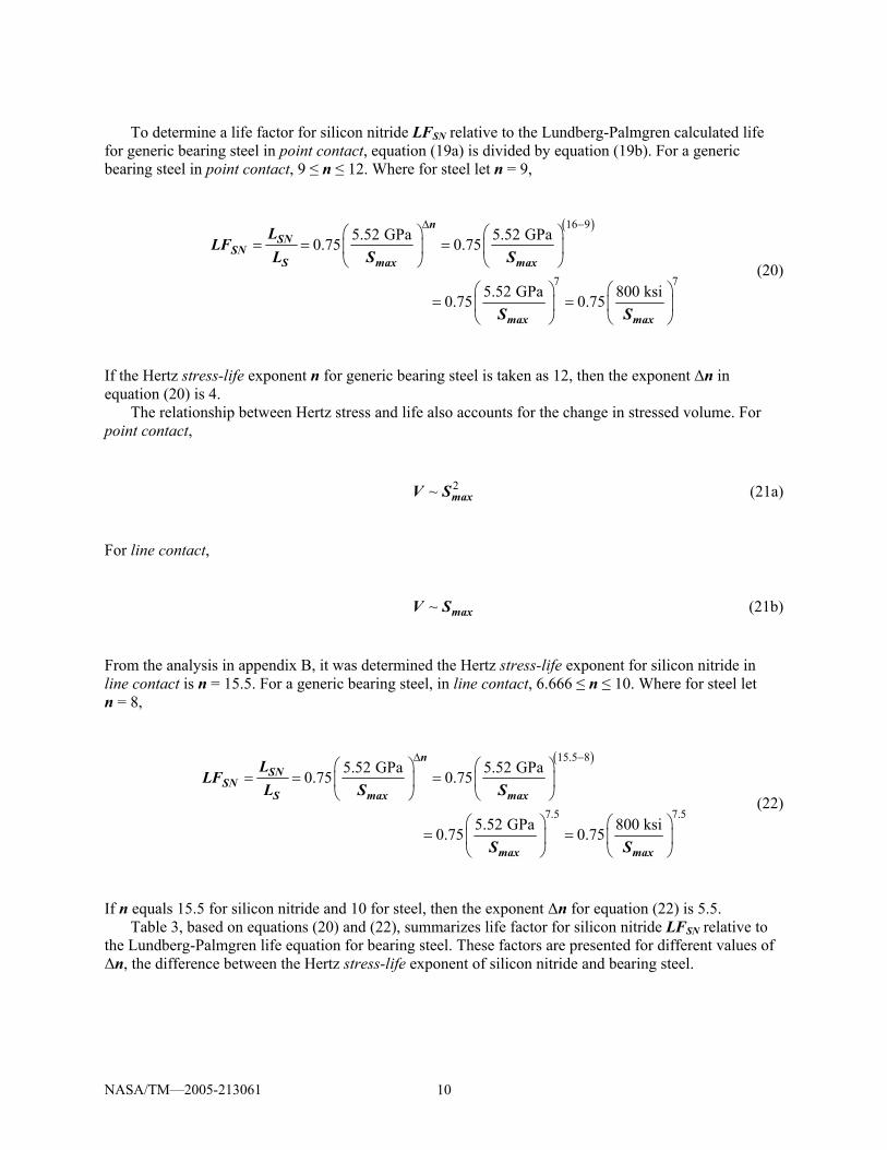
To determine a life factor for silicon nitride LFSN relative to the Lundberg-Palmgren calculated life
for generic bearing steel in point contact, equation (19a) is divided by equation (19b). For a generic bearing steel in point contact, 9 ≤ n ≤ 12. Where for steel let n = 9,
( )16 9
7 7
5.52 GPa 5.52 GPa0.75 0.75
5.52 GPa 800 ksi0.75 0.75
∆ −⎛ ⎞ ⎛ ⎞
= = =⎜ ⎟ ⎜ ⎟⎝ ⎠ ⎝ ⎠
⎛ ⎞ ⎛ ⎞= =⎜ ⎟ ⎜ ⎟
⎝ ⎠ ⎝ ⎠
nSN
SNS max max
max max
LLF
L S S
S S
(20)
If the Hertz stress-life exponent n for generic bearing steel is taken as 12, then the exponent ∆n in equation (20) is 4.
The relationship between Hertz stress and life also accounts for the change in stressed volume. For point contact,
2~ maxV S (21a) For line contact,
~ maxV S (21b) From the analysis in appendix B, it was determined the Hertz stress-life exponent for silicon nitride in line contact is n = 15.5. For a generic bearing steel, in line contact, 6.666 ≤ n ≤ 10. Where for steel let n = 8,
( )15.5 8
7.5 7.5
5.52 GPa 5.52 GPa0.75 0.75
5.52 GPa 800 ksi0.75 0.75
∆ −⎛ ⎞ ⎛ ⎞
= = =⎜ ⎟ ⎜ ⎟⎝ ⎠ ⎝ ⎠
⎛ ⎞ ⎛ ⎞= =⎜ ⎟ ⎜ ⎟
⎝ ⎠ ⎝ ⎠
nSN
SNS max max
max max
LLF
L S S
S S
(22)
If n equals 15.5 for silicon nitride and 10 for steel, then the exponent ∆n for equation (22) is 5.5.
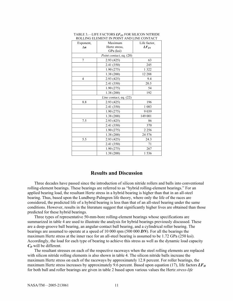
Table 3, based on equations (20) and (22), summarizes life factor for silicon nitride LFSN relative to the Lundberg-Palmgren life equation for bearing steel. These factors are presented for different values of ∆n, the difference between the Hertz stress-life exponent of silicon nitride and bearing steel.
NASA/TM—2005-213061 11
TABLE 3.—LIFE FACTORS LFSN FOR SILICON NITRIDE
ROLLING ELEMENT IN POINT AND LINE CONTACT Exponent,
∆n Maximum
Hertz stress, GPa (ksi)
Life factor, LFSN
Point contact, eq. (20) 7 2.93 (425) 63 2.41 (350) 245 1.90 (275) 1 322 1.38 (200) 12 288
4 2.93 (425) 9.4 2.41 (350) 20.5 1.90 (275) 54 1.38 (200) 192
Line contact, eq. (22) 8.8 2.93 (425) 196 2.41 (350) 1 083 1.90 (275) 9 039 1.38 (200) 149 001
7.5 2.93 (425) 86 2.41 (350) 370 1.90 (275) 2 256 1.38 (200) 24 576
5.5 2.93 (425) 24.3 2.41 (350) 71 1.90 (275) 267 1.38 (200) 1 536
Results and Discussion Three decades have passed since the introduction of silicon nitride rollers and balls into conventional
rolling-element bearings. These bearings are referred to as “hybrid rolling-element bearings.” For an applied bearing load, the resultant Hertz stress in a hybrid bearing is higher than that in an all-steel bearing. Thus, based upon the Lundberg-Palmgren life theory, where only the life of the races are considered, the predicted life of a hybrid bearing is less than that of an all-steel bearing under the same conditions. However, results in the literature suggest that significantly higher lives are obtained than those predicted for these hybrid bearings.
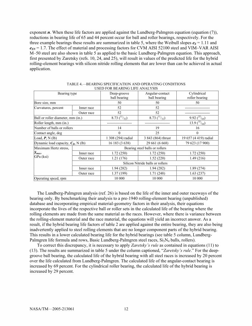
Three types of representative 50-mm-bore rolling-element bearings whose specifications are summarized in table 4 are used to illustrate the analysis for hybrid bearings previously discussed. These are a deep-groove ball bearing, an angular-contact ball bearing, and a cylindrical roller bearing. The bearings are assumed to operate at a speed of 10 000 rpm (500 000 DN). For all the bearings the maximum Hertz stress at the inner race for an all-steel bearing is assumed to be 1.72 GPa (250 ksi). Accordingly, the load for each type of bearing to achieve this stress as well as the dynamic load capacity CD will be different.
The resultant stresses on each of the respective raceways when the steel rolling elements are replaced with silicon nitride rolling elements is also shown in table 4. The silicon nitride balls increase the maximum Hertz stress on each of the raceways by approximately 12.8 percent. For roller bearings, the maximum Hertz stress increases by approximately 9.6 percent. Based upon equation (17), life factors LFH for both ball and roller bearings are given in table 2 based upon various values the Hertz stress-life
NASA/TM—2005-213061 12
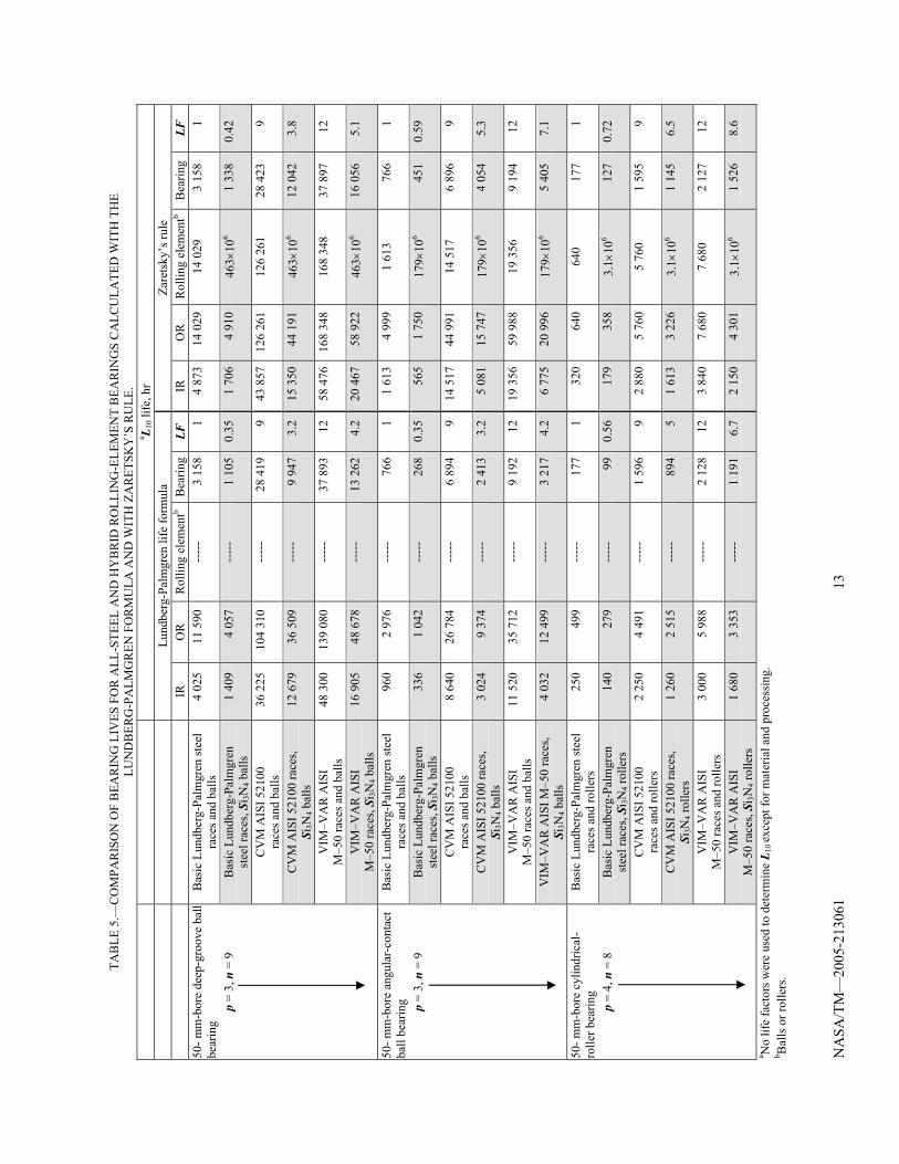
exponent n. When these life factors are applied against the Lundberg-Palmgren equation (equation (7)), reductions in bearing life of 65 and 44 percent occur for ball and roller bearings, respectively. For the three example bearings these results are summarized in table 5, where the Weibull slopes eS = 1.11 and eSN = 1.7. The effect of material and processing factors for CVM AISI 52100 steel and VIM–VAR AISI M–50 steel are also shown in table 5 as applied to the basic Lundberg-Palmgren equation. This approach, first presented by Zaretsky (refs. 10, 24, and 25), will result in values of the predicted life for the hybrid rolling-element bearings with silicon nitride rolling elements that are lower than can be achieved in actual application.
TABLE 4.—BEARING SPECIFICATION AND OPERATING CONDITIONS USED FOR BEARING LIFE ANALYSIS
Bearing type Deep-groove ball bearing
Angular-contact ball bearing
Cylindrical roller bearing
Bore size, mm 50 50 50 Inner race 52 52 -------------------- Curvatures, percent Outer race 52 52 --------------------
Ball or roller diameter, mm (in.) 8.73 (11/32) 8.73 (11/32) 9.92 (25/64) Roller length, mm (in.) -------------------- -------------------- 13.9 (35/64) Number of balls or rollers 14 19 16 Contact angle, deg 0 25 0 Load, P, N (lb) 1 308 (294) radial 3 843 (864) thrust 19 657 (4 419) radial Dynamic load capacity, CD, N (lb) 16 183 (3 638) 29 661 (6 668) 79 623 (17 900)
Bearing steel balls or rollers Inner race 1.72 (250) 1.72 (250) 1.72 (250) Outer race 1.21 (176) 1.52 (220) 1.49 (216)
Silicon Nitride balls or rollers Inner race 1.94 (282) 1.94 (282) 1.89 (274)
Maximum Hertz stress, Smax, GPa (ksi)
Outer race 1.37 (199) 1.71 (248) 1.63 (237) Operating speed, rpm 10 000 10 000 10 000
The Lundberg-Palmgren analysis (ref. 26) is based on the life of the inner and outer raceways of the
bearing only. By benchmarking their analysis to a pre-1940 rolling-element bearing (unpublished) database and incorporating empirical material-geometry factors in their analysis, their equations incorporate the lives of the respective ball or roller sets in the calculated life of the bearing where the rolling elements are made from the same material as the races. However, where there is variance between the rolling-element material and the race material, the equations will yield an incorrect answer. As a result, if the hybrid bearing life factors of table 2 are applied against the entire bearing, they are also being inadvertently applied to steel rolling elements that are no longer component parts of the hybrid bearing. This results in a lower calculated bearing life for the hybrid bearings (see table 5 column, Lundberg-Palmgren life formula and rows, Basic Lundberg-Palmgren steel races, Si3N4 balls, rollers).
To correct this discrepancy, it is necessary to apply Zaretsky’s rule as contained in equations (11) to (13). The results are summarized in table 5 under the column captioned, “Zaretsky’s rule.” For the deep-groove ball bearing, the calculated life of the hybrid bearing with all steel races is increased by 20 percent over the life calculated from Lundberg-Palmgren. The calculated life of the angular-contact bearing is increased by 69 percent. For the cylindrical roller bearing, the calculated life of the hybrid bearing is increased by 29 percent.
NA
SA/T
M—
2005
-213
061
13
TAB
LE 5
.—C
OM
PAR
ISO
N O
F B
EAR
ING
LIV
ES F
OR
ALL
-STE
EL A
ND
HY
BR
ID R
OLL
ING
-ELE
MEN
T B
EAR
ING
S C
ALC
ULA
TED
WIT
H T
HE
LU
ND
BER
G-P
ALM
GR
EN F
OR
MU
LA A
ND
WIT
H Z
AR
ETSK
Y’S
RU
LE.
a L 10 l
ife, h
r
Lu
ndbe
rg-P
alm
gren
life
form
ula
Zare
tsky
’s ru
le
IR
OR
R
ollin
g el
emen
tb B
earin
g LF
IR
O
R
Rol
ling
elem
entb
Bea
ring
LF
50- m
m-b
ore
deep
-gro
ove
ball
bear
ing
Bas
ic L
undb
erg-
Palm
gren
stee
l ra
ces a
nd b
alls
4 02
5
11 5
90
----
-
3 15
8
1 4
873
14
029
14
029
3 15
8
1
p =
3, n
= 9
B
asic
Lun
dber
g-Pa
lmgr
en
stee
l rac
es, S
i 3N4 b
alls
1 40
9
4 05
7 --
---
1
105
0.
35
1 70
6
4 91
0 46
3×10
6
1 33
8
0.42
C
VM
AIS
I 521
00
race
s and
bal
ls
36
225
104
310
----
-
28 4
19
9 43
857
126
261
12
6 26
1
28 4
23
9
C
VM
AIS
I 521
00 ra
ces,
Si3N
4 bal
ls
12
679
36 5
09
----
-
9 94
7
3.2
15 3
50
44 1
91
463×
106
12
042
3.8
V
IM–V
AR
AIS
I M
–50
race
s and
bal
ls
48
300
139
080
----
-
37 8
93
12
58 4
76 1
68 3
48
168
348
37
897
12
V
IM–V
AR
AIS
I M
–50
race
s, Si
3N4 b
alls
16 9
05
48
678
--
---
13
262
4.
2 20
467
58
922
46
3×10
6
16 0
56
5.
1
50- m
m-b
ore
angu
lar-
cont
act
ball
bear
ing
Bas
ic L
undb
erg-
Palm
gren
stee
l ra
ces a
nd b
alls
960
2
976
----
-
766
1
1 61
3
4 99
9 1
613
76
6
1
p =
3, n
= 9
B
asic
Lun
dber
g-Pa
lmgr
en
stee
l rac
es, S
i 3N4 b
alls
336
1
042
----
-
268
0.
35
565
1
750
179×
106
45
1
0.59
C
VM
AIS
I 521
00
race
s and
bal
ls
8
640
26
784
--
---
6
894
9
14 5
17
44 9
91
14 5
17
6
896
9
C
VM
AIS
I 521
00 ra
ces,
Si3N
4 bal
ls
3
024
9
374
----
-
2 41
3
3.2
5 08
1
15 7
47
179×
106
4
054
5.
3
V
IM–V
AR
AIS
I M
–50
race
s and
bal
ls
11
520
35 7
12
----
-
9 19
2
12
19 3
56
59 9
88
19 3
56
9
194
12
V
IM–V
AR
AIS
I M–5
0 ra
ces,
Si3N
4 bal
ls
4
032
12
499
--
---
3
217
4.
2 6
775
20
996
17
9×10
6
5 40
5
7.1
50- m
m-b
ore
cylin
dric
al-
rolle
r bea
ring
Bas
ic L
undb
erg-
Palm
gren
stee
l ra
ces a
nd ro
llers
250
49
9 --
---
17
7
1 32
0
640
640
17
7
1
p =
4, n
= 8
B
asic
Lun
dber
g-Pa
lmgr
en
stee
l rac
es, S
i 3N4 r
olle
rs
14
0
279
----
-
99
0.56
17
9
358
3.1×
106
12
7
0.72
C
VM
AIS
I 521
00
race
s and
rolle
rs
2
250
4
491
----
-
1 59
6
9 2
880
5
760
5 76
0
1 59
5
9
C
VM
AIS
I 521
00 ra
ces,
Si3N
4 rol
lers
1 26
0
2 51
5 --
---
89
4
5 1
613
3
226
3.1×
106
1
145
6.
5
V
IM–V
AR
AIS
I M
–50
race
s and
rolle
rs
3
000
5
988
----
-
2 12
8
12
3 84
0
7 68
0 7
680
2
127
12
V
IM–V
AR
AIS
I M
–50
race
s, Si
3N4 r
olle
rs
1
680
3
353
----
-
1 19
1
6.7
2 15
0
4 30
1 3.
1×10
6
1 52
6
8.6
a No
life
fact
ors w
ere
used
to d
eter
min
e L 1
0 ex
cept
for m
ater
ial a
nd p
roce
ssin
g.
b Bal
ls o
r rol
lers
.
NASA/TM—2005-213061 14
Anecdotal field experience suggests that even when applying Zaretsky’s rule to the Lundberg-Palmgren equations, the life of the hybrid bearings are significantly higher than that calculated for hybrid bearings whose races are manufactured from AISI 52100 and AISI M–50 bearing steels. From table 5 under the column captioned, “Zaretsky’s rule” the hybrid bearings are predicted to have a lower fatigue life than the all-steel bearings by 58 percent for deep-groove bearings, 41 percent for angular-contact bearings, and 28 percent for cylindrical roller bearings. Resultant life factors LFH based upon the Lundberg-Palmgren equations applying Zaretsky’s rule are summarized in table 6.
TABLE 6.—SUMMARY OF LIFE FACTORS LFH BASED ON LUNDBERG-PALMGREN FORMULA AND ZARETSKY’S RULE FOR HYBRID
SILICON NITRIDE ROLLING-ELEMENT BEARINGS Bearing type Life factor,
LFH Life reduction,a
percent Deep-groove ball bearing 0.42 58 Angular-contact ball bearing 0.59 41 Cylindrical roller bearing 0.72 28 aReduction from life of an all-steel bearing.
Can a hybrid bearing exhibit a statistically longer life than that calculated by the Lundberg-Palmgren
equations for an all-steel bearing including life factors for material and processing? The answer must be a qualified yes. Based upon the Zaretsky life equation (equation (10)) and a large database that is now available (refs. 33 to 35), it can be reasonably concluded that the Lundberg-Palmgren formula underpredicts bearing life.
As previously discussed, the Lundberg-Palmgren formula for ball bearings incorporates a value of the load-life exponent p = 3 and for roller bearings, p = 10/3. These values are based on pre-1940, air-melt, AISI 52100 steel. Based on the data base reported by Parker and Zaretsky (ref. 36) and summarized in reference 37, for vacuum-processed post-1960 bearing steels, the value of the load-life exponent p for ball bearings is 4 and for roller bearings, 5.
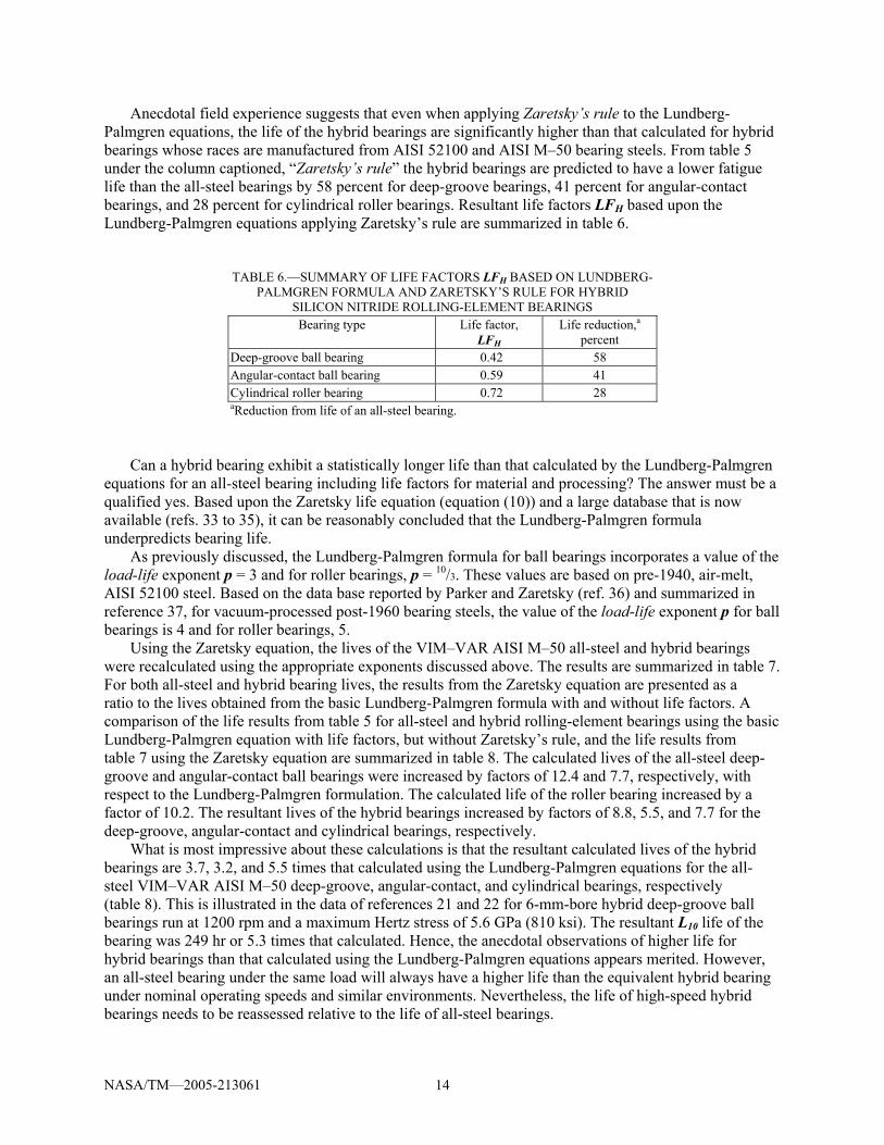
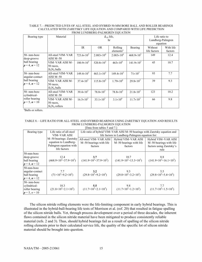
Using the Zaretsky equation, the lives of the VIM–VAR AISI M–50 all-steel and hybrid bearings were recalculated using the appropriate exponents discussed above. The results are summarized in table 7. For both all-steel and hybrid bearing lives, the results from the Zaretsky equation are presented as a ratio to the lives obtained from the basic Lundberg-Palmgren formula with and without life factors. A comparison of the life results from table 5 for all-steel and hybrid rolling-element bearings using the basic Lundberg-Palmgren equation with life factors, but without Zaretsky’s rule, and the life results from table 7 using the Zaretsky equation are summarized in table 8. The calculated lives of the all-steel deep-groove and angular-contact ball bearings were increased by factors of 12.4 and 7.7, respectively, with respect to the Lundberg-Palmgren formulation. The calculated life of the roller bearing increased by a factor of 10.2. The resultant lives of the hybrid bearings increased by factors of 8.8, 5.5, and 7.7 for the deep-groove, angular-contact and cylindrical bearings, respectively.
What is most impressive about these calculations is that the resultant calculated lives of the hybrid bearings are 3.7, 3.2, and 5.5 times that calculated using the Lundberg-Palmgren equations for the all-steel VIM–VAR AISI M–50 deep-groove, angular-contact, and cylindrical bearings, respectively (table 8). This is illustrated in the data of references 21 and 22 for 6-mm-bore hybrid deep-groove ball bearings run at 1200 rpm and a maximum Hertz stress of 5.6 GPa (810 ksi). The resultant L10 life of the bearing was 249 hr or 5.3 times that calculated. Hence, the anecdotal observations of higher life for hybrid bearings than that calculated using the Lundberg-Palmgren equations appears merited. However, an all-steel bearing under the same load will always have a higher life than the equivalent hybrid bearing under nominal operating speeds and similar environments. Nevertheless, the life of high-speed hybrid bearings needs to be reassessed relative to the life of all-steel bearings.
NASA/TM—2005-213061 15
TABLE 7.—PREDICTED LIVES OF ALL-STEEL AND HYBRID 50-MM BORE BALL AND ROLLER BEARINGS CALCULATED WITH ZARETSKY LIFE EQUATION AND COMPARED WITH LIFE PREDICTION
FROM LUNDBERG-PALMGREN EQUATION L10 life,
hr Life ratio to
Lundberg-Palmgren equation
Bearing type Material
IR OR Rolling elementsa
Bearing Without life factors
With life factors
All-steel VIM–VAR AISI M–50
723.6×10³ 2.083×10⁶ 2.083×10⁶ 468.9×10³ 149 12.4 50- mm-bore deep-groove ball bearing p = 4, n = 12
VIM–VAR AISI M–50 races, Si3N4 balls
180.9×10³ 520.8×10³ 463×106 141.9×10³ 45 10.7
All-steel VIM–VAR AISI M–50
149.4×10³ 463.1×10³ 149.4×10³ 71×103 93 7.7 50- mm-bore angular-contact ball bearing p = 4, n = 12
VIM–VAR AISI M–50 races, Si3N4 balls
37.4×10³ 115.8×10³ 1.79×10⁶ 29.8×10³ 39 9.3
All-steel VIM–VAR AISI M–50
39.4×10³ 78.8×10³ 78.8×10³ 21.8×10³ 123 10.2 50- mm-bore cylindrical- roller bearing p = 5, n = 10
VIM–VAR AISI M–50 races, Si3N4 rollers
16.5×10³ 33.1×10³ 3.1×10⁶ 11.7×10³ 66 9.8
aBalls or rollers.
TABLE 8.—LIFE RATIO FOR ALL-STEEL AND HYBRID BEARINGS USING ZARETSKY EQUATION AND RESULTS FROM LUNDBERG-PALMGREN EQUATION
[Data from tables 5 and 7.] Life ratio of hybrid VIM–VAR AISI M–50 bearings with Zaretsky equation and
life factors to Lundberg-Palmgren equation for: Bearing type Life ratio of all-steel
VIM–VAR AISI M–50 bearings: Zaretsky
equation to Lundberg-Palmgren equation with
life factors
All-steel VIM–VAR AISI M–50 bearings with life
factors
Hybrid VIM–VAR AISI M–50 bearings with life
factors
Hybrid VIM–VAR AISI M–50 bearings with life factors using Zaretsky’s
rule 50-mm-bore deep-groove ball bearing p = 4, n = 12
12.4 (468.9×10³÷37.9×10³)
3.7 (141.9×10³÷37.9×10³)
10.7 (141.9×10³÷13.3×10³)
8.8 (141.9×10³÷16.1×10³)
50-mm-bore angular-contact ball bearing p = 4, n = 12
7.7 (71×103÷9.2×10³)
3.2 (29.8×10³÷9.2×10³)
9.3 (29.8×10³÷3.2×10³)
5.5 (29.8×10³÷5.4×10³)
50- mm-bore cylindrical- roller bearing p = 5, n = 10
10.3 (21.8×10³÷2.1×10³)
5.5 (11.7×10³÷2.1×10³)
9.8 (11.7×10³÷1.2×10³)
7.7 (11.7×10³÷1.5×10³)
The silicon nitride rolling elements were the life-limiting component in early hybrid bearings. This is
illustrated in the hybrid-ball-bearing life tests of Morrison et al. (ref. 20) that resulted in fatigue spalling of the silicon nitride balls. Yet, through process development over a period of three decades, the inherent flaws contained in the silicon nitride material have been mitigated to produce consistently reliable material (refs. 2 and 3). Thus, should hybrid bearings fail as a result of spalling of the silicon nitride rolling elements prior to their calculated service life, the quality of the specific lot of silicon nitride material should be brought into question.
NASA/TM—2005-213061 16
Summary of Results Three decades have passed since the introduction of silicon nitride rollers and balls into conventional
rolling-element bearings. For a given applied load, the contact (Hertz) stress in a hybrid bearing will be higher than an all-steel rolling-element bearing, where all the components are manufactured from hardened bearing steel. Using the Lundberg-Palmgren equations, the life of the hybrid bearing is predicted to be less than an all-steel bearing of the same type. However, experimental data and anecdotal observations suggest higher lives for hybrid bearings than those calculated using the Lundberg-Palmgren equations, even when the differences in material properties between the rolling elements and races including the Hertz stress-life exponents were taken into consideration. The rolling-element life as well as the race lives were used to determine the resultant bearing life of the hybrid and all-steel bearings. Based upon the Zaretsky life equation, the predicted lives of hybrid silicon nitride bearings were theoretically compared with that predicted for all-steel bearings and the actual lives reported in the literature. The following results were obtained:
1. An all-steel bearing under the same load will have a longer life than the equivalent hybrid bearing
under nominal operating speeds and similar environments. 2. Life factors derived for hybrid bearings based upon the Lundberg-Palmgren equations are dependent
on the bearing type. The life factors for deep-groove, angular-contact, and cylindrical roller hybrid bearings are 0.42, 0.59, and 0.72, respectively. These life factors are multiplied by the calculated life of an all-steel bearing using the Lundberg-Palmgren formula to obtain the hybrid bearing life.
3. The Lundberg-Palmgren equations underpredict bearing life. Under nominal operating speeds, the resultant calculated lives of the deep-groove, angular-contact, and cylindrical roller hybrid bearings with races made of post-1960 bearing steel increased by factors of 3.7, 3.2, and 5.5, respectively, from those calculated using the Lundberg-Palmgren equations.
References
1. Dee, C.W. (1970), “Silicon Nitride—Tribological Applications of a Ceramic Material,” Tribology, 3, 2, pp. 89–92.
2. Chao, L.Y., Shetty, D.K., Adair, J.H., and Mecholsky, J.J., Jr., (1995), “Development of Silicon Nitride for Rolling-Contact Applications: A Review,” Jour. Materials Education 17, 5–6, pp. 245–303.
3. Wang, L., Snidle, R.W., and Gu, L., (2000), “Rolling Contact Silicon Nitride Bearing Technology: A Review of Recent Research,” Wear, 246, pp. 159–173.
4. Scott, D., Blackwell, J., and McCullah, P.J., (1971), “Silicon Nitride as a Rolling Bearing Material—A Preliminary Assessment,” Wear, 17, 1, pp. 73–82.
5. Scott, D., and Blackwell, J., (1973), “Hot-Pressed Silicon Nitride as a Rolling Bearing Material—A Preliminary Assessment,” Wear, 24, 1, pp. 61–67.
6. Baumgartner, H.R., and Whieldon, W.M., (1973), “Rolling Contact Fatigue Performance of Hot-Pressed Silicon Nitride versus Surface Preparation Techniques,” in: Surfaces and Interfaces of Glass and Ceramics, V.D. Frechette, W.C. LaCourse, and V.L. Burdick, eds., Plenum Press, New York, pp. 179–193.
7. Baumgartner, H.R., (1973), “Evaluation of Roller Bearing Contacting Hot Pressed Silicon Nitride Rolling Elements,” in: Ceramics for High Performance Applications, J.J. Burke, E. Gorum, and R.N. Katz, eds., Brook Hill Publishing Co., Chestnut Hill, MA, pp. 713–727.
8. Baumgartner, H.R., Lundberg, D.V., and Whieldon, W.M., (1973), “Silicon Nitride in Rolling contact Bearings,” Norton Co., Worcester, MA (available NTIS, AD–A031560).
NASA/TM—2005-213061 17
9. Parker, R.J., and Zaretsky, E.V., (1974), Rolling-Element Fatigue Life of Silicon Nitride Balls,” NASA TN D–7794.
10. Zaretsky, E.V., (1989), “Ceramic Bearings for Use in Gas Turbine Engines,” ASME Jour. Gas Turbines and Power, 111, 1, pp. 146–157.
11. Sundberg, D.V., (1974), Ceramic Roller Bearings for High Speed and High Temperature Applications, SAE Paper No. 740241.
12. Baumgartner, H.R. and Cowley, P.E., (1975), “Silicon Nitride in Rolling Contact Bearings,” AMMRC–CTR–76–5 (available NTIS AD–A025350).
13. Baumgartner, H.R., Calvert, G.S., and Cowley, P.E., (1976), “Ceramic Materials in Rolling Contact Bearings,” Norton Co., Worcester, MA (available NTIS AD–A031560).
14. Reddecliff, J.M., and Valorie, R., (1976), “The Performance of a High-Speed Ball Thrust Bearing Using Silicon Nitride Balls,” ASME Jour. of Lubrication Tech., 98, 4, pp. 553–563.
15. Miner, J.R., Grace, W.A., and Valorie, R., (1981), “A Demonstration of High-Speed Gas Turbine Bearings Using Silicon Nitride Rolling Elements,” Lubrication Engineering, 37, 8, pp. 462–464, 473–478.
16. Miner, J.R., Dell, J., Galbato, A.T., and Ragen, M.A., (1998), “F117-PW-100 Hybrid Ball Bearing Ceramic Technology Insertion,” ASME Jour. of Engineering for Gas Turbines and Power, 118, 2, pp. 434–442.
17. Bailey, T.E., (1984), “Ceramic Roller Bearing Development Program,” NAPC–PE–106–C (available NTIS, AD–B086767L).
18. Hosang, G.W., (1987), “Results and Design Techniques From the Application of Ceramic Ball Bearings to the MERADCOM 10KW Turbine,” AIAA Paper No. 87–1844.
19. Parker, R.J., and Zaretsky, E.V., (1975), “Fatigue Life of High-Speed Ball Bearings With Silicon Nitride Balls,” ASME Jour. of Lubrication Tech., 97, 3, pp. 553–563.
20. Morrison, F.R., McCool, J.I., Yonushonis, T.M., and Weinberg, P., (1984), “The Load-Life Relationship for M–50 Steel Bearings With Silicon Nitride Balls,” Lubrication Engineering, 40, 3, pp.153–159.
21. Komeya, K., and Kotani, H., (1986), “Development of Ceramic Antifriction Bearing,” JSAE Review, 3, 3, pp. 72–79.
22. Tanimoto, K., and Ikeda, T., (2000), “Evaluation of Extra-Small Ceramic Ball Bearings,” KOYO Engineering Journal English Edition, 156E (2000), pp. 23–29.
23. Tanimoto, K., Kajihara, K. and Yanai, K., (2000), “Hybrid Ceramic Ball Bearings for Turbochargers,” SAE Paper No. 2000–01–1339.
24. Zaretsky, E.V. (1992), STLE Life Factors for Rolling Bearings, STLE SP-34, STLE, Park Ridge, IL, pp. 92–95.
25. Zaretsky, E.V. (1997), “Rolling Bearing and Gear Materials,” Tribology for Aerospace Applications, E.V. Zaretsky, ed., STLE SP–37, STLE, Park Ridge, IL, pp. 432–442.
26. Lundberg, G., and Palmgren, A. (1947), “Dynamic Capacity of Rolling Bearings,” Acta Polytechnica, 1, 3, Stockholm.
27. Weibull, W. (1939), “A Statistical Theory of the Strength of Materials,” Ingeniors Etanskaps Akademien-Handlinger, 151.
28. Weibull, W. (1939), “The Phenomenon of Rupture of Solids,” Ingeniors Vetenskaps Akademien, 153. 29. Weibull, W. (1951), “A Statistical Distribution Function of Wide Applicability,” ASME Jour. of
Applied Mechanics, 18, 3, pp. 293–297. 30. Lundberg, G., and Palmgren, A. (1952), “Dynamic Capacity of Roller Bearings,” Ingeniors Etanskaps
Akademien-Handlinger, 210. 31. Zaretsky, E.V. (1994), “Design for Life, Plan for Death, Machine Design, 66, 15, Aug., 1994,
pp. 55–59. 32. Jones, A.B., (1946), Analysis of Stresses and Deflections, Vols. I and II, General Motors, New
Departure Division, Bristol, CT.
NASA/TM—2005-213061 18
33. Harris, T.A. (1995), “Final Report-Establishment of a New Rolling Bearing Contact Life Calculation Method,” U.S. Naval Air Warfare Center, Aircraft Division Trenton, Contract No. N68335–93–C–0111.
34. Harris, T.A., and McCool, J.I. (1996), “On Accuracy of Rolling Bearing Fatigue Life Prediction,” ASME Jour. of Trib., 118, 2, pp. 297–310.
35. Vlcek, B.L., Hendricks, R.C., and Zaretsky, E.V. (2003), “Determination of Rolling-Element Fatigue Life from Computer Generated Bearing Tests,” Trib. Trans., 46, 4, pp. 479–493.
36. Parker, R.J., and Zaretsky, E.V., (1972), “Reevaluation of the Stress-Life Relation in Rolling-Element Bearings,” NASA TN D–6745.
37. Zaretsky, E.V. (1997), “Rolling Bearing and Gear Materials,” Tribology for Aerospace Applications, E.V. Zaretsky, ed., STLE SP–37, STLE, Park Ridge, IL, pp. 398–405.
NASA/TM—2005-213061 19
Appendix A Effect of Modulus of Elasticity and Poisson’s Ratio on Contact Stress and Life
Point Contact Stress and Life
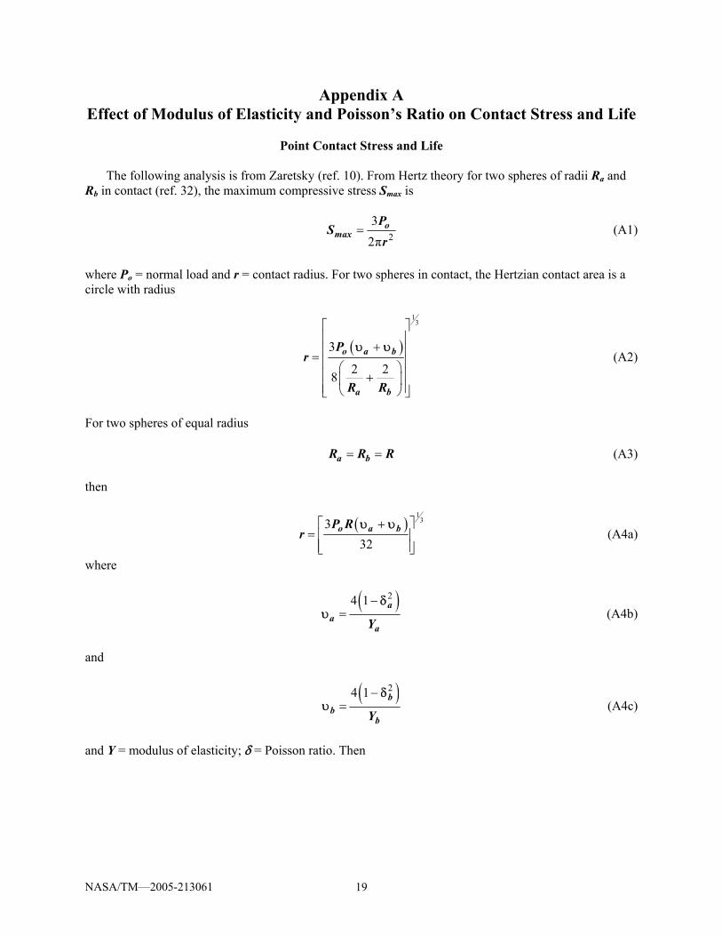
The following analysis is from Zaretsky (ref. 10). From Hertz theory for two spheres of radii Ra and
Rb in contact (ref. 32), the maximum compressive stress Smax is
23
2π= o
maxP
Sr
(A1)
where Po = normal load and r = contact radius. For two spheres in contact, the Hertzian contact area is a circle with radius
( )
13
3
2 28
⎡ ⎤⎢ ⎥
+⎢ ⎥= ⎢ ⎥⎛ ⎞⎢ ⎥+⎜ ⎟⎢ ⎥⎝ ⎠⎣ ⎦
o a b
a b
Pr
R R
υ υ (A2)
For two spheres of equal radius
= =a bR R R (A3) then
( )
133
32⎡ ⎤+
= ⎢ ⎥⎢ ⎥⎣ ⎦
o a bP Rr
υ υ (A4a)
where
( )24 1−
=a
aaY
δυ (A4b)
and
( )24 1−
=b
bbY
δυ (A4c)
and Y = modulus of elasticity; δ = Poisson ratio. Then
NASA/TM—2005-213061 20
( ) ( )
13
13
2 2
1
2 2
1
1 1
1 1
⎡ ⎤− −= +⎢ ⎥
⎢ ⎥⎣ ⎦
⎡ ⎤− + −⎢ ⎥= ⎢ ⎥⎢ ⎥⎣ ⎦
a b
a b
b a a b
a b
r KY Y
Y YK
Y Y
δ δ
δ δ (A5a)
where
1
3
13
8⎡ ⎤
= ⎢ ⎥⎣ ⎦
oP RK (A5b)
Substituting equations (A5a) and (A5b) into equation (A1)
( ) ( )
23
2 2 21 1
⎡ ⎤⎢ ⎥= ⎢ ⎥− + −⎢ ⎥⎣ ⎦
a bmax H
b a a b
Y YS K
Y Yδ δ (A6a)
where
1
3
2 26π 9⎡ ⎤
= ⎢ ⎥⎣ ⎦
oPK
R (A6b)
For steel on steel
( )
23
2 22 1
⎡ ⎤⎢ ⎥= ⎢ ⎥−⎢ ⎥⎣ ⎦
ss
maxs
YS K
δ (A7)
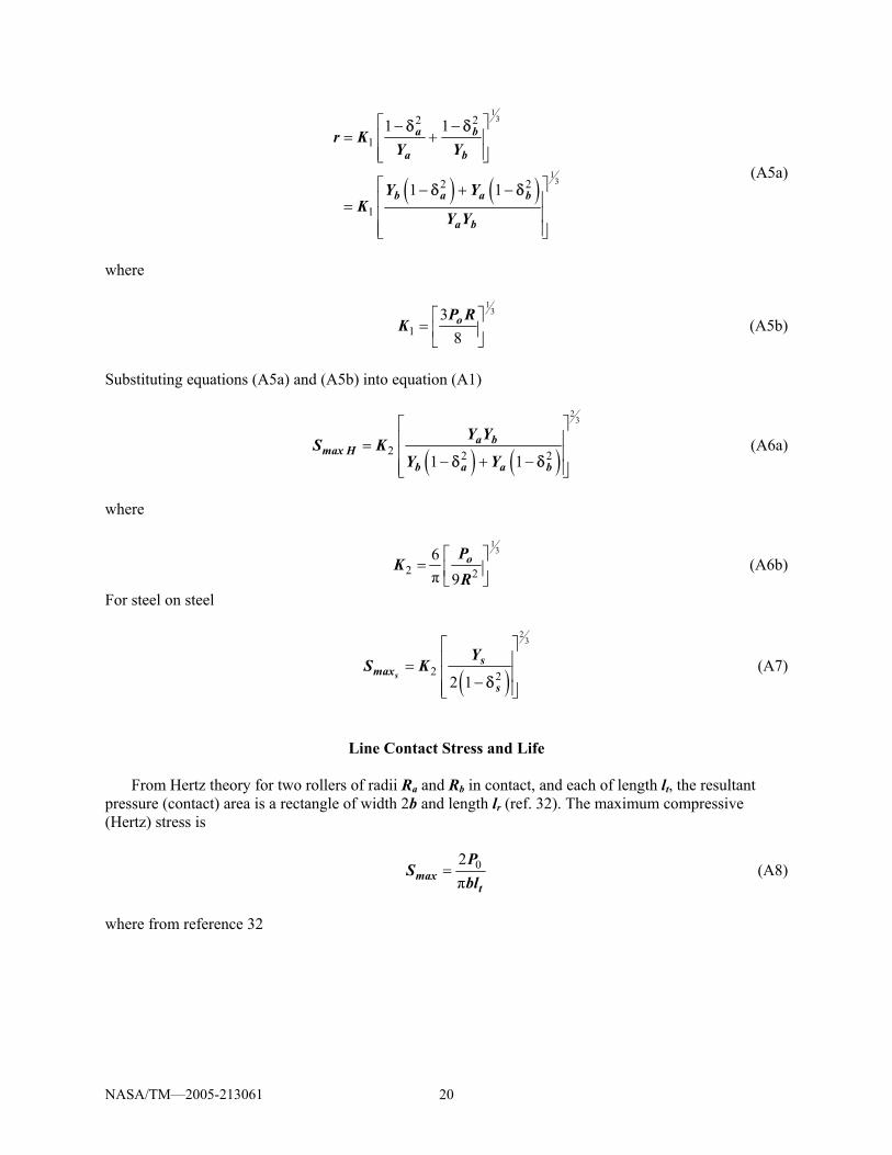
Line Contact Stress and Life From Hertz theory for two rollers of radii Ra and Rb in contact, and each of length lt, the resultant
pressure (contact) area is a rectangle of width 2b and length lr (ref. 32). The maximum compressive (Hertz) stress is
02π
=maxt
PS
bl (A8)
where from reference 32
NASA/TM—2005-213061 21
( )
12
1 1π
⎡ ⎤⎢ ⎥
+⎢ ⎥= ⎢ ⎥⎛ ⎞⎢ ⎥+⎜ ⎟⎢ ⎥⎝ ⎠⎣ ⎦
o a b
ta b
Pb
lR R
υ υ (A9)
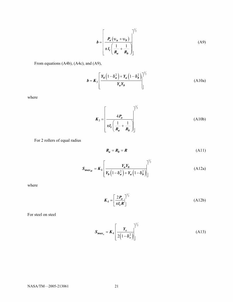
From equations (A4b), (A4c), and (A9),
( ) ( )
122 2
3
1 1⎡ ⎤− + −⎢ ⎥= ⎢ ⎥⎢ ⎥⎣ ⎦
b a a b
a b
Y Yb K
Y Y
δ δ (A10a)
where
12
341 1π
⎡ ⎤⎢ ⎥⎢ ⎥= ⎢ ⎥⎛ ⎞⎢ ⎥+⎜ ⎟⎢ ⎥⎝ ⎠⎣ ⎦
o
ta b
PK
lR R
(A10b)
For 2 rollers of equal radius = =a bR R R (A11)
( ) ( )
12
4 2 21 1
⎡ ⎤⎢ ⎥= ⎢ ⎥− + −⎢ ⎥⎣ ⎦
Ha b
maxb a a b
Y YS K
Y Yδ δ (A12a)
where
1
2
42π⎡ ⎤
= ⎢ ⎥⎣ ⎦
o
t
PK
l R (A12b)
For steel on steel
( )
12
4 22 1
⎡ ⎤⎢ ⎥= ⎢ ⎥−⎢ ⎥⎣ ⎦
ss
maxs
YS K
δ (A13)
NASA/TM—2005-213061 22
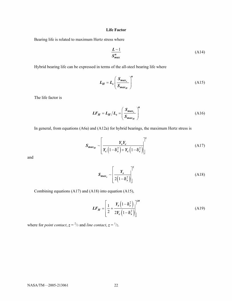
Life Factor Bearing life is related to maximum Hertz stress where
~ 1nmax
LS
(A14)
Hybrid bearing life can be expressed in terms of the all-steel bearing life where
⎛ ⎞
= ⎜ ⎟⎜ ⎟⎝ ⎠
s
H
nmax
H smax
SL L
S (A15)
The life factor is
⎛ ⎞
= = ⎜ ⎟⎜ ⎟⎝ ⎠
s
H
nmax
H H smax
SLF L L
S (A16)
In general, from equations (A6a) and (A12a) for hybrid bearings, the maximum Hertz stress is
( ) ( )2 2
~1 1
⎡ ⎤⎢ ⎥⎢ ⎥− + −⎢ ⎥⎣ ⎦
H
z
s cmax
c s c c
Y YS
Y Yδ δ (A17)
and
( )2
~2 1
⎡ ⎤⎢ ⎥⎢ ⎥−⎢ ⎥⎣ ⎦
s
z
smax
s
YS
δ (A18)
Combining equations (A17) and (A18) into equation (A15),
( )( )
2
2
112 2 1
⎡ ⎤−⎢ ⎥= +⎢ ⎥−⎢ ⎥⎣ ⎦
zns c
Hc s
YLF
Y
δ
δ (A19)
where for point contact, z = 2/3 and line contact, z = 1/2.
NASA/TM—2005-213061 23
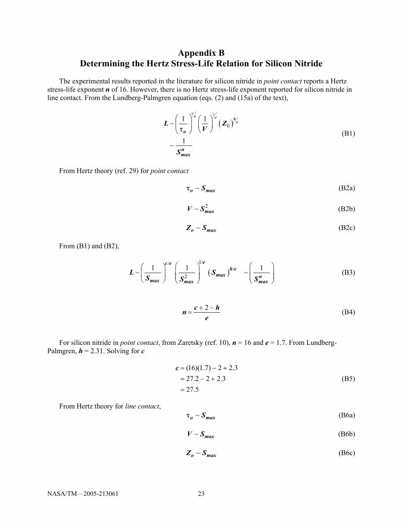
Appendix B Determining the Hertz Stress-Life Relation for Silicon Nitride
The experimental results reported in the literature for silicon nitride in point contact reports a Hertz
stress-life exponent n of 16. However, there is no Hertz stress-life exponent reported for silicon nitride in line contact. From the Lundberg-Palmgren equation (eqs. (2) and (15a) of the text),
( )
1
01 1~
1~
⎛ ⎞ ⎛ ⎞⎜ ⎟ ⎜ ⎟
⎝ ⎠⎝ ⎠
ce e h
e
o
nmax
L ZV
S
τ (B1)
From Hertz theory (ref. 29) for point contact ~o maxSτ (B2a) 2~ maxV S (B2b) ~o maxZ S (B2c) From (B1) and (B2),
( )1//
/2
1 1 1~ ~⎛ ⎞ ⎛ ⎞⎛ ⎞⎜ ⎟ ⎜ ⎟⎜ ⎟ ⎜ ⎟ ⎜ ⎟⎝ ⎠ ⎝ ⎠ ⎝ ⎠
ec eh e
max nmax max max
L SS S S
(B3)
2+ −=
c hne
(B4)
For silicon nitride in point contact, from Zaretsky (ref. 10), n = 16 and e = 1.7. From Lundberg-
Palmgren, h = 2.31. Solving for c
(16)(1.7) 2 2.327.2 2 2.327.5
= − += − +=
c (B5)
From Hertz theory for line contact, ~o maxSτ (B6a) ~ maxV S (B6b) ~o maxZ S (B6c)
NASA/TM—2005-213061 24
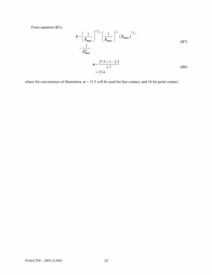
From equation (B1),
( )
27.5 1 2.31.7 1.7 1.71 1~
1~
⎛ ⎞ ⎛ ⎞⎜ ⎟ ⎜ ⎟⎝ ⎠ ⎝ ⎠
maxmax max
nmax
L SS S
S
(B7)
27.5 1 2.3
1.715.4
+ −=
=
n (B8)
where for convenience of illustration, n = 15.5 will be used for line contact, and 16 for point contact.
This publication is available from the NASA Center for AeroSpace Information, 301–621–0390.
REPORT DOCUMENTATION PAGE
2. REPORT DATE
19. SECURITY CLASSIFICATION OF ABSTRACT
18. SECURITY CLASSIFICATION OF THIS PAGE
Public reporting burden for this collection of information is estimated to average 1 hour per response, including the time for reviewing instructions, searching existing data sources,gathering and maintaining the data needed, and completing and reviewing the collection of information. Send comments regarding this burden estimate or any other aspect of thiscollection of information, including suggestions for reducing this burden, to Washington Headquarters Services, Directorate for Information Operations and Reports, 1215 JeffersonDavis Highway, Suite 1204, Arlington, VA 22202-4302, and to the Office of Management and Budget, Paperwork Reduction Project (0704-0188), Washington, DC 20503.
NSN 7540-01-280-5500 Standard Form 298 (Rev. 2-89)Prescribed by ANSI Std. Z39-18298-102
Form Approved
OMB No. 0704-0188
12b. DISTRIBUTION CODE
8. PERFORMING ORGANIZATION REPORT NUMBER
5. FUNDING NUMBERS
3. REPORT TYPE AND DATES COVERED
4. TITLE AND SUBTITLE
6. AUTHOR(S)
7. PERFORMING ORGANIZATION NAME(S) AND ADDRESS(ES)
11. SUPPLEMENTARY NOTES
12a. DISTRIBUTION/AVAILABILITY STATEMENT
13. ABSTRACT (Maximum 200 words)
14. SUBJECT TERMS
17. SECURITY CLASSIFICATION OF REPORT
16. PRICE CODE
15. NUMBER OF PAGES
20. LIMITATION OF ABSTRACT
Unclassified Unclassified
Technical Memorandum
Unclassified
National Aeronautics and Space AdministrationJohn H. Glenn Research Center at Lewis FieldCleveland, Ohio 44135–3191
1. AGENCY USE ONLY (Leave blank)
10. SPONSORING/MONITORING AGENCY REPORT NUMBER
9. SPONSORING/MONITORING AGENCY NAME(S) AND ADDRESS(ES)
National Aeronautics and Space AdministrationWashington, DC 20546–0001
Available electronically at http://gltrs.grc.nasa.gov
April 2005
NASA TM—2005-213061TRIB2004–64246
E–14521–1
WBS–22–714–09–16
30
Effect of Silicon Nitride Balls and Rollers on Rolling Bearing Life
Erwin V. Zaretsky, Brian L. Vlcek, and Robert C. Hendricks
Hybrid rolling bearings; Bearing life prediction; Silicon nitride rolling elements
Unclassified -UnlimitedSubject Categories: 37, 38, and 39
Prepared for the 2004 International Joint Tribology Conference cosponsored by the American Society of MechanicalEngineers and the Society of Tribologists and Lubrication Engineers, Long Beach, California, October 24–27, 2004.Erwin V. Zaretsky and Robert C. Hendricks, NASA Glenn Research Center; and Brian L. Vlcek, Georgia SouthernUniversity, Statesboro, Georgia 30460. Responsible person, Erwin V. Zaretsky, organization code RS, 216–433–3241.
Three decades have passed since the introduction of silicon nitride rollers and balls into conventional rolling-elementbearings. For a given applied load, the contact (Hertz) stress in a hybrid bearing will be higher than an all-steel rolling-element bearing. The silicon nitride rolling-element life as well as the lives of the steel races were used to determinethe resultant bearing life of both hybrid and all-steel bearings. Life factors were determined and reported for hybridbearings. Under nominal operating speeds, the resultant calculated lives of the deep-groove, angular-contact, andcylindrical roller hybrid bearings with races made of post-1960 bearing steel increased by factors of 3.7, 3.2, and 5.5,respectively, from those calculated using the Lundberg-Palmgren equations. An all-steel bearing under the same loadwill have a longer life than the equivalent hybrid bearing under the same conditions. Under these conditions, hybridbearings are predicted to have a lower fatigue life than all-steel bearings by 58 percent for deep-groove bearings, 41percent for angular-contact bearings, and 28 percent for cylindrical roller bearings.