Embed Size (px)
Citation preview
Effect of Powder Injection on the InterfacialFracture Toughness of Plasma-Sprayed
ZirconiaYoshifumi Okajima, Toshio Nakamura, and Sanjay Sampath
(Submitted July 9, 2012; in revised form January 14, 2013)
Adhesive strength of the plasma-sprayed thermal barrier coating is one of the most important parameterswhich influence their durability and reliability during service. While many methods exist to measure theadhesive strength, in general, they require cumbersome and time-consuming specimen preparation.Furthermore, considerations of the adhesion strength from the point-of-view of fracture toughness or forthat matter, their systematic correlation to both processing variances are limited. Consequently, there isan opportunity to both simplify the measurement procedure and establish correlations among methodsand linkages between processing parameters and interfacial fracture toughness. In this paper, we reportresults on adhesion strength of plasma-sprayed yttria-stabilized zirconia (YSZ) coating on aluminumsubstrates based on both interfacial indentation test (to measure interfacial fracture toughness) and themodified tensile adhesive test. Carrier gas flow for powder injection into the plasma torch was system-atically varied to introduce variances in particle melting with concomitant impact on the measuredadhesive strength. The results indicate the correlation between the particle melting index and themeasured interfacial fracture toughness.
Keywords adhesive strength, gas turbines, interface cracking,tensile bond strength, thermal barrier coatings(TBCs), turbine blades, yttria-stabilized zirconia(YSZ)
1. Introduction
Plasma-sprayed zirconia coatings on superalloy com-ponents play a critical role as thermal barrier coatings(TBCs) in heavy duty gas turbines and aircraft enginescomponents (Ref 1). It is widely appreciated that plasmaspray is a highly complex deposition process with a mul-titude of interdependent variables resulting in manyinstances with large variability in coating microstructure
and properties (Ref 2). There has been extensive effortaround the world to enhance understanding and control ofplasma spray processes particularly from the perspectiveof TBC applications. Efforts are underway in all aspects ofprocess advances including novel torch designs, controlledfeedstock powder, process map strategy, and manipula-tions of deposition conditions to improve repeatability andreproducibility. Among the parameters of interest, radialparticle injection into the DC plasma torch is of particularimportance. Past work (Ref 3) has shown that there existsa �sweet spot’’ for optimum injection which is controlledby the carrier gas flow rate. This can affect the meltingstate of the particles and thus affect process efficiency andrepeatability. It has been shown that optimum injection cansignificantly improve both deposit efficiency and reducevariability in coating modulus and residual stresses.
This study seeks to determine if such an optimizationprotocol can also influence the coating-substrate adhesion, acritical system level parameter for life prediction. Prior toestablishing the correlation between process and properties, itis important to ensure that a robust, simple, and representativetesting procedure is introduced. Although numerous testmethods were developed (Ref 4-7), it is of importance tochoose the most appropriate test method and evaluation cri-teria. A brief review of available methods is presented below.
Chicot et al. (Ref 8) proposed and discussed the evalu-ation of the interfacial fracture toughness at the metalcoating/substrate interface by means of an indentation test.The major advantage of this methodology is that it isapplicable to complex geometries; however, it requiresmeasurements of crack lengths which can be highly sub-jective given the complex and anisotropic microstructure of
This article is an invited paper selected from presentations at the2012 International Thermal Spray Conference and has beenexpanded from the original presentation. It is simultaneouslypublished in Thermal Spray 2012: Proceedings of theInternational Thermal Spray Conference, Air, Land, Water, andthe Human Body: Thermal Spray Science and Applications,Houston, Texas, USA, May 21-24, 2012, Basil R. Marple, ArvindAgarwal, Laura Filofteia-Toma, Margaret M. Hyland, Yuk-ChiuLau, Chang-Jiu Li, Rogerio S. Lima, and Andre McDonald, Ed.,ASM International, Materials Park, OH, 2012.
Yoshifumi Okajima, Gas Turbine Engineering Department,Mitsubishi Heavy Industries, Ltd., Takasago, HyogoJapan; andToshio Nakamura and Sanjay Sampath, State University of NewYork at Stony Brook, Stony Brook, NY. Contact e-mail:[email protected].
JTTEE5 22:166–174
DOI: 10.1007/s11666-013-9898-7
1059-9630/$19.00 � ASM International
166—Volume 22(2-3) March 2013 Journal of Thermal Spray Technology
Peer
Revie
wed
the spray coating. Watanabe et al. (Ref 9) proposed andapplied a modified tensile adhesive test for HVOF coatings.The benefit of this approach is it provides a single quanti-tative measure of adhesion but is often subject to uncer-tainties with application of the adhesive glue and knowledgeof the failure origin. To overcome the challenges in eachof these techniques, we have sought to use both of thesetest methods in our study. Of further importance is the apriori knowledge of coating stresses and elastic mod-ulus which was obtained using in situ and ex situ beamcurvature monitoring. Although a typical TBC comprises athree-layer system, to assess the process parameter effects,yttria-stabilized zirconia (YSZ) coatings were deposited onaluminum substrates so as to provide sufficient thermalmismatch for curvature measurement and simplify theanalysis. It is envisioned that such a combined experimentalstrategy will not only provide confirmatory correlation ofthe process-property correlations but also elucidate differ-ences among the measurement methods.
2. Experimental Procedure
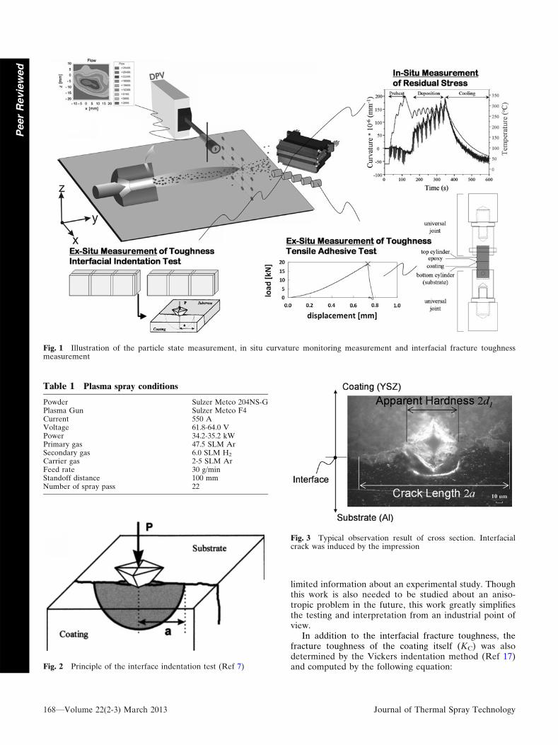
Figure 1 shows a schematic of the experimental proce-dure. A particle injection study was conducted for externalinjection DC plasma generated with an 8 mm nozzle (modelF4 gun, Sulzer Metco, Westbury, NY, USA). Commerciallyavailable YSZ (204NS-G, Sulzer Metco, Westbury, NY,USA) was used as the powder in this study with nominal sizedistribution of 10-75 lm. Chemical composition of thepowder is 7-9% Y2O3, 0.7%(max) SiO2, 0.2%(max) TiO2,0.2%(max) Al2O3, 0.2%(max) Fe2O3, and balance ZrO2.Other than carrier gas flow variation, all other processparameters were kept constant as shown in Table 1.In-flight particle diagnostics was conducted to measureparticle state parameters by a single particle method (DPV-2000, Tecnar Automation Ltd., Canada). This was measuredfor each of the injection conditions. The coating residualstress and in-plane modulus EC were measured by an in situcurvature monitoring method (Ref 10). Coatings weredeposited on grit-blasted aluminum beams with dimensionsL = 228.6 mm and W = 25.4 mm, respectively. The sampleswere preheated with the plasma to about 200 �C prior todeposition of coatings. The detail of the measurementmethod is described elsewhere (Ref 10). Following thedeposition onto the curvature beam, each sample was thencut into several parts for the interfacial indentation test.Concurrent with the curvature measurements, coatings weresimultaneously sprayed onto a tensile adhesion test cylinderfor adhesion measurements using ASTM C633 test. The testwas modified following the procedure established byWatanabe et al. (Ref 9) inducing a pre-crack at the edges.
In the next section, we discuss the details of the two testmethods.
2.1 Interfacial Indentation Test
In recent years, the interfacial indentation test hasbeen proposed to characterize the adhesion properties
of plasma-sprayed coatings (Ref 8). This test is nowoften used as an alternative to other tests (Ref 11-13).The principle of the test is to perform a set of con-ventional Vickers indentations on the cross section ofthe sample in order to initiate and propagate a crackat the existing interface between the coating andsubstrate. This test follows the classical indentationfracture toughness measurements developed for bulkceramics.
In the present study, samples were cut from aluminumbeams, which were processed on the curvature sensor. Thethicknesses of the zirconia coatings were in the range of0.2-0.32 mm depending on the injection condition. Aftermounting in epoxy resin, the sample cross sections wereground with sand paper from grade 120 to 1200 and,subsequently, by a final diamond polishing from 9 to0.5 lm.
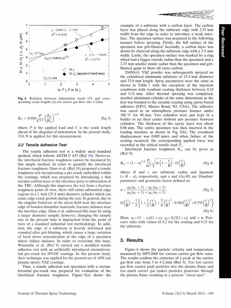
For the interfacial indentation test, Vickers indentationtests were conducted with four loads: 9.8, 19.6, 49.0, and98.1 N and five indentations were performed under eachload. Loading time was 15 s. Prior to indentation, thediagonal of the Vickers indenter was aligned withthe interface. The schematic of the test is shown in Fig. 2.The half-diagonal of the indenter d1 and the crack length aalong the interface was measured by digital image analysison the optical microscope picture (Fig. 3). They wereplotted as a function of the applied load in bi-logarithmicscale (i.e., ln P-ln d1 and ln P-ln a) (Fig. 4). Finally, thecritical value (Pc, ac) was determined as the point ofintersection between the extrapolated lines of ln P-ln d1
and ln P-ln a.Apparent interfacial fracture toughness Kic can be
defined as (Ref 8),
Kic ¼ 0:015Pc
a3=2c
E
H
� �1=2
i
; ðEq 1Þ
where
ðE=HÞ1=2i ¼ ðES=HSÞ1=2
1þ ðHS=HCÞ1=2þ ðEC=HCÞ1=2
1þ ðHC=HSÞ1=2; ðEq 2Þ
where E and H are Young�s modulus and Vickershardness, and the subscripts i, C, and S denote interface,coating, and substrate, respectively. Elastic modulus, ES
of the aluminum used was 70 GPa. EC was obtained fromthe in situ curvature monitoring method for each speci-men. This study primarily considers the in-plane inter-facial fracture toughness which is the critical parameterfor comparison to adhesion measurements in thesecoatings and as such does not include the effect ofanisotropy. In general, the in-plane toughness is an orderof magnitude lower than the out-of-plane toughness forthermal-sprayed materials (Ref 14). Furthermore, thecurvature measurements also rely on in-plane modulus.As such, the assumptions and interpretations are self-consistent from an anisotropy point of view. Althoughwork on the anisotropic problem for interfacial fracturetoughness has begun and aspects relating to this problemare currently being analyzed (Ref 15, 16), there is still
Journal of Thermal Spray Technology Volume 22(2-3) March 2013—167
Peer
Revie
wed
limited information about an experimental study. Thoughthis work is also needed to be studied about an aniso-tropic problem in the future, this work greatly simplifiesthe testing and interpretation from an industrial point ofview.
In addition to the interfacial fracture toughness, thefracture toughness of the coating itself (KC) was alsodetermined by the Vickers indentation method (Ref 17)and computed by the following equation:
Fig. 1 Illustration of the particle state measurement, in situ curvature monitoring measurement and interfacial fracture toughnessmeasurement
Table 1 Plasma spray conditions
Powder Sulzer Metco 204NS-GPlasma Gun Sulzer Metco F4Current 550 AVoltage 61.8-64.0 VPower 34.2-35.2 kWPrimary gas 47.5 SLM ArSecondary gas 6.0 SLM H2
Carrier gas 2-5 SLM ArFeed rate 30 g/minStandoff distance 100 mmNumber of spray pass 22
Fig. 2 Principle of the interface indentation test (Ref 7)
Fig. 3 Typical observation result of cross section. Interfacialcrack was induced by the impression
168—Volume 22(2-3) March 2013 Journal of Thermal Spray Technology
Peer
Revie
wed
KC ¼ 0:016P
C3=2
EC
HC
� �1=2
; ðEq 3Þ
where P is the applied load and C is the crack lengthahead of the diagonal of indentation. In the present study,19.6 N is applied for this measurement.
2.2 Tensile Adhesive Test
The tensile adhesion test is a widely used standardmethod, which follows ASTM C 633 (Ref 18). However,the interfacial fracture toughness cannot be measured bythis simple method. In order to quantify the interfacialfracture toughness, Qian et al. (Ref 19) proposed a tensiletoughness test incorporating a pre-crack embedded withinthe coatings, which was prepared by introducing a thincircular carbon layer at the interface prior to fabrication ofthe TBC. Although this improves the test from a fracturetoughness point of view, there still exists substantial edgeregions in a 1 inch (25.4 mm) diameter cylinder which cancause edge crack growth during the test. In general, due tothe singular behavior of the stress field near the interfaceedge of bonded dissimilar materials, fracture initiates nearthe interface edge. Qian et al. addressed this issue by usinga larger diameter sample; however, changing the samplesize at the present time is impractical from the point ofview of a standard industrial test methodology. In addi-tion, the edge of a substrate is heavily deformed androunded after grit-blasting, which causes a large variationof local stress concentration at the edge of a specimenwhere failure initiates. In order to overcome this issue,Watanabe et al. (Ref 9) carried out a modified tensileadhesive test with an artificially introduced circumferen-tial pre-crack for HVOF coatings. In this present study,their technique was applied for the present set of APS (airplasma spray) YSZ coatings.
Thus, a tensile adhesion test specimen with a circum-ferential pre-crack was prepared for evaluation of theinterfacial fracture toughness. Figure 5(a) shows the
example of a substrate with a carbon layer. The carbonlayer was placed along the substrate edge with 2.33 mmwidth from the edge in order to introduce a weak inter-face. The specimen surface was prepared in the followingmanner before spraying. Firstly, the full surface of thespecimen was grit-blasted. Secondly, a carbon layer wasdrawn by charcoal along the substrate edge with a 3-5 mmwidth. Lastly, the specimen surface was masked by a ringwhich had a bigger outside radius than the specimen and a2.33 mm smaller inside radius than the specimen and grit-blasted again to blow off extra carbon.
204NS-G YSZ powder was subsequently sprayed onthe cylindrical aluminum substrate of 25.4 mm diameterand 33.0 mm length. Spray parameters were the same asshown in Table 1 with the exception of the injectionconditions with resultant coating thickness between 0.24and 0.31 mm. After thermal spraying was completed,another aluminum cylinder of the same dimensions as thefirst was bonded to the ceramic coating using epoxy-basedadhesive (EP15, Master Bond, NJ, USA). The adhesivewas cured in an atmospheric pressure furnace under160 �C for 90 min. Two cylinders were just kept in aholder to set their center without any pressure betweencylinders. The thickness of the epoxy layer was about0.06 mm. The entire specimen was then inserted in theloading machine as shown in Fig. 5(b). The crossheaddisplacement was 0.005 mm/s and when failure of thecoating occurred, the corresponding applied force wasrecorded as the critical tensile load Pc.
Interfacial fracture toughness Ktc can be given as(Ref 9):
Ktc ¼ ð1� aÞ1=2 Pc
pc2
ffiffiffiffiffiffiffiffiffiffiffiffiffiffiffiffiffiffiffiffiffiffiffipc 1� c
R
� �r�G c
R
� �; ðEq 4Þ
where R and c are substrate radius and ligament(= R � a), respectively, and a and G(c/R) are Dundurs�parameter and geometric factor defined as:
a ¼ lSðjC þ 1Þ � lCðjS þ 1ÞlSðjC þ 1Þ þ lCðjS þ 1Þ ; ðEq 5Þ
Gc
R
� �¼ 1
21þ 1
2
c
R
� �þ 3
8
c
R
� �2
�0:363c
R
� �3
þ0:731c
R
� �4� �
:
ðEq 6Þ
Here, jj = (3 � mj)/(1 + mj), lj = Ej/2(1 + mj) and m is Pois-son�s ratio with values of 0.2 for the coating and 0.33 forthe substrate.
3. Results
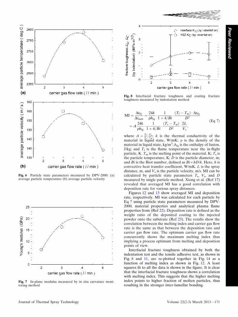
Figure 6 shows the particle velocity and temperaturemeasured by DPV2000 for various carrier gas flow rates.The results confirm the existence of a peak at the carriergas flow rate from 3 to 4 L/min (Ref 3). Too low carriergas flow cannot push particles into the plasma flame andtoo much carrier gas makes particles penetrate throughthe plasma flame resulting in a process ‘‘sweet-spot’’.
Fig. 4 Relation between indentation loads (P) and corre-sponding crack lengths (a) for carrier gas flow rate 4 l/min
Journal of Thermal Spray Technology Volume 22(2-3) March 2013—169
Peer
Revie
wed
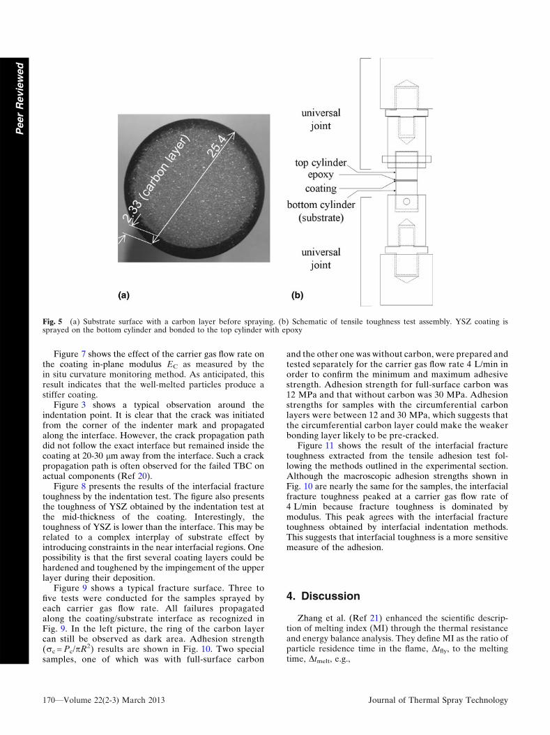
Figure 7 shows the effect of the carrier gas flow rate onthe coating in-plane modulus EC as measured by thein situ curvature monitoring method. As anticipated, thisresult indicates that the well-melted particles produce astiffer coating.
Figure 3 shows a typical observation around theindentation point. It is clear that the crack was initiatedfrom the corner of the indenter mark and propagatedalong the interface. However, the crack propagation pathdid not follow the exact interface but remained inside thecoating at 20-30 lm away from the interface. Such a crackpropagation path is often observed for the failed TBC onactual components (Ref 20).
Figure 8 presents the results of the interfacial fracturetoughness by the indentation test. The figure also presentsthe toughness of YSZ obtained by the indentation test atthe mid-thickness of the coating. Interestingly, thetoughness of YSZ is lower than the interface. This may berelated to a complex interplay of substrate effect byintroducing constraints in the near interfacial regions. Onepossibility is that the first several coating layers could behardened and toughened by the impingement of the upperlayer during their deposition.
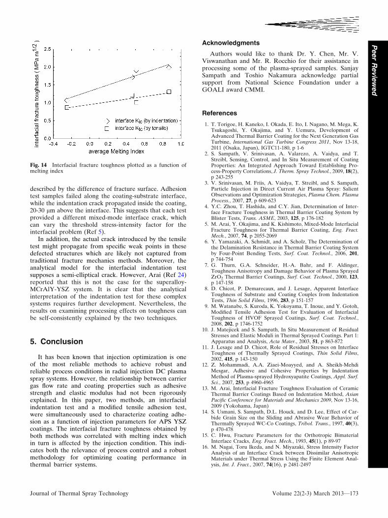
Figure 9 shows a typical fracture surface. Three tofive tests were conducted for the samples sprayed byeach carrier gas flow rate. All failures propagatedalong the coating/substrate interface as recognized inFig. 9. In the left picture, the ring of the carbon layercan still be observed as dark area. Adhesion strength(rc = Pc/pR2) results are shown in Fig. 10. Two specialsamples, one of which was with full-surface carbon
and the other one was without carbon, were prepared andtested separately for the carrier gas flow rate 4 L/min inorder to confirm the minimum and maximum adhesivestrength. Adhesion strength for full-surface carbon was12 MPa and that without carbon was 30 MPa. Adhesionstrengths for samples with the circumferential carbonlayers were between 12 and 30 MPa, which suggests thatthe circumferential carbon layer could make the weakerbonding layer likely to be pre-cracked.
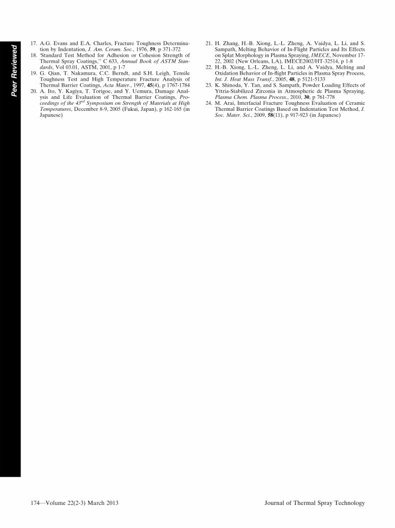
Figure 11 shows the result of the interfacial fracturetoughness extracted from the tensile adhesion test fol-lowing the methods outlined in the experimental section.Although the macroscopic adhesion strengths shown inFig. 10 are nearly the same for the samples, the interfacialfracture toughness peaked at a carrier gas flow rate of4 L/min because fracture toughness is dominated bymodulus. This peak agrees with the interfacial fracturetoughness obtained by interfacial indentation methods.This suggests that interfacial toughness is a more sensitivemeasure of the adhesion.
4. Discussion
Zhang et al. (Ref 21) enhanced the scientific descrip-tion of melting index (MI) through the thermal resistanceand energy balance analysis. They define MI as the ratio ofparticle residence time in the flame, Dtfly, to the meltingtime, Dtmelt, e.g.,
Fig. 5 (a) Substrate surface with a carbon layer before spraying. (b) Schematic of tensile toughness test assembly. YSZ coating issprayed on the bottom cylinder and bonded to the top cylinder with epoxy
170—Volume 22(2-3) March 2013 Journal of Thermal Spray Technology
Peer
Revie
wed
MI ¼ DtflyDtmelt
¼ 24k
qhfg� 1
1þ 4=Bi� ðTf � TmÞ � Dtfly
D2
¼ A24k
qhfg� 1
1þ 4=Bi� ðTs � TmÞ
D2� 2L
Vs;
ðEq 7Þ
where A ¼ Tf�Tm
Ts�Tm; k is the thermal conductivity of the
material in liquid state, W/mK; q is the density of thematerial in liquid state, kg/m3; hfg is the enthalpy of fusion,J/kg; and Tf is the flame temperature near the in-flightparticle, K. Tm is the melting point of the material, K; Ts isthe particle temperature, K; D is the particle diameter, m;and Bi is the Biot number, defined as Bi = hD/k. Here, h isconvective heat transfer coefficient, W/mK. L is the spraydistance, m, and Vs is the particle velocity, m/s. MI can becalculated by particle state parameters Ts, Vs, and Dmeasured by single particle method. Xiong et al. (Ref 17)revealed that averaged MI has a good correlation withdeposition rate for various spray distances.
Figures 12 and 13 show averaged MI and depositionrate, respectively. MI was calculated for each particle byEq 7 using particle state parameters measured by DPV-2000, material properties and analytical plasma flameproperties from (Ref 22). Deposition rate is defined as theweight ratio of the deposited coating to the injectedpowder onto the substrate (Ref 23). The results show thecorrelation between the melting index and carrier gas flowrate is the same as that between the deposition rate andcarrier gas flow rate. The optimum carrier gas flow rateconcurrently shows the maximum melting index thusimplying a process optimum from melting and depositionpoints of view.
Interfacial fracture toughness obtained by both theindentation test and the tensile adhesive test, as shown inFig. 8 and 11, are re-plotted together in Fig. 14 as afunction of melting index as shown in Fig. 12. A leastsquares fit to all the data is shown in the figure. It is clearthat the interfacial fracture toughness shows a correlationwith melting index. This suggests that the higher meltingindex points to higher fraction of molten particles, thusresulting in the stronger inter-lamellar bonding.
Fig. 6 Particle state parameters measured by DPV-2000: (a)average particle temperature (b) average particle velocity
Fig. 7 In-plane modulus measured by in situ curvature moni-toring method
Fig. 8 Interfacial fracture toughness and coating fracturetoughness measured by indentation method
Journal of Thermal Spray Technology Volume 22(2-3) March 2013—171
Peer
Revie
wed
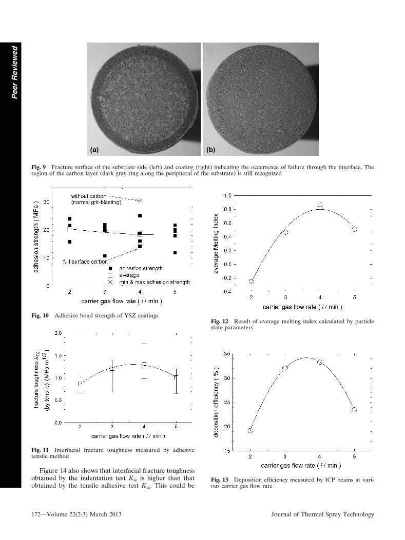
Figure 14 also shows that interfacial fracture toughnessobtained by the indentation test Kic is higher than thatobtained by the tensile adhesive test Ktc. This could be
Fig. 9 Fracture surface of the substrate side (left) and coating (right) indicating the occurrence of failure through the interface. Theregion of the carbon layer (dark gray ring along the peripheral of the substrate) is still recognized
Fig. 10 Adhesive bond strength of YSZ coatings
Fig. 11 Interfacial fracture toughness measured by adhesivetensile method
Fig. 12 Result of average melting index calculated by particlestate parameters
Fig. 13 Deposition efficiency measured by ICP beams at vari-ous carrier gas flow rate
172—Volume 22(2-3) March 2013 Journal of Thermal Spray Technology
Peer
Revie
wed
described by the difference of fracture surface. Adhesiontest samples failed along the coating-substrate interface,while the indentation crack propagated inside the coating,20-30 lm above the interface. This suggests that each testprovided a different mixed-mode interface crack, whichcan vary the threshold stress-intensity factor for theinterfacial problem (Ref 5).
In addition, the actual crack introduced by the tensiletest might propagate from specific weak points in thesedefected structures which are likely not captured fromtraditional fracture mechanics methods. Moreover, theanalytical model for the interfacial indentation testsupposes a semi-elliptical crack. However, Arai (Ref 24)reported that this is not the case for the superalloy-MCrAlY-YSZ system. It is clear that the analyticalinterpretation of the indentation test for these complexsystems requires further development. Nevertheless, theresults on examining processing effects on toughness canbe self-consistently explained by the two techniques.
5. Conclusion
It has been known that injection optimization is oneof the most reliable methods to achieve robust andreliable process conditions in radial injection DC plasmaspray systems. However, the relationship between carriergas flow rate and coating properties such as adhesivestrength and elastic modulus had not been rigorouslyexplained. In this paper, two methods, an interfacialindentation test and a modified tensile adhesion test,were simultaneously used to characterize coating adhe-sion as a function of injection parameters for APS YSZcoatings. The interfacial fracture toughness obtained byboth methods was correlated with melting index whichin turn is affected by the injection condition. This indi-cates both the relevance of process control and a robustmethodology for optimizing coating performance inthermal barrier systems.
Acknowledgments
Authors would like to thank Dr. Y. Chen, Mr. V.Viswanathan and Mr. R. Rocchio for their assistance inprocessing some of the plasma-sprayed samples. SanjaySampath and Toshio Nakamura acknowledge partialsupport from National Science Foundation under aGOALI award CMMI.
References
1. T. Torigoe, H. Kaneko, I. Okada, E. Ito, I. Nagano, M. Mega, K.Tsukagoshi, Y. Okajima, and Y. Uemura, Development ofAdvanced Thermal Barrier Coating for the Next Generation GasTurbine, International Gas Turbine Congress 2011, Nov 13-18,2011 (Osaka, Japan), IGTC11-180, p 1-6
2. S. Sampath, V. Srinivasan, A. Valarezo, A. Vaidya, and T.Streibl, Sensing, Control, and In Situ Measurement of CoatingProperties: An Integrated Approach Toward Establishing Pro-cess-Property Correlations, J. Therm. Spray Technol., 2009, 18(2),p 243-255
3. V. Srinivasan, M. Friis, A. Vaidya, T. Streibl, and S. Sampath,Particle Injection in Direct Current Air Plasma Spray: SalientObservations and Optimization Strategies, Plasma Chem. PlasmaProcess., 2007, 27, p 609-623
4. Y.C. Zhou, T. Hashida, and C.Y. Jian, Determination of Inter-face Fracture Toughness in Thermal Barrier Coating System byBlister Tests, Trans. ASME, 2003, 125, p 176-182
5. M. Arai, Y. Okajima, and K. Kishimoto, Mixed-Mode InterfacialFracture Toughness for Thermal Barrier Coating, Eng. Fract.Mech., 2007, 74, p 2055-2069
6. Y. Yamazaki, A. Schmidt, and A. Scholz, The Determination ofthe Delamination Resistance in Thermal Barrier Coating Systemby Four-Point Bending Tests, Surf. Coat. Technol., 2006, 201,p 744-754
7. G. Thurn, G.A. Schneider, H.-A. Bahr, and F. Aldinger,Toughness Anisotropy and Damage Behavior of Plasma SprayedZrO2 Thermal Barrier Coatings, Surf. Coat. Technol., 2000, 123,p 147-158
8. D. Chicot, P. Demarecaux, and J. Lesage, Apparent InterfaceToughness of Substrate and Coating Couples from IndentationTests, Thin Solid Films, 1996, 283, p 151-157
9. M. Watanabe, S. Kuroda, K. Yokoyama, T. Inoue, and Y. Gotoh,Modified Tensile Adhesion Test for Evaluation of InterfacialToughness of HVOF Sprayed Coatings, Surf. Coat. Technol.,2008, 202, p 1746-1752
10. J. Matejicek and S. Sampath, In Situ Measurement of ResidualStresses and Elastic Moduli in Thermal Sprayed Coatings. Part 1:Apparatus and Analysis, Acta Mater., 2003, 51, p 863-872
11. J. Lesage and D. Chicot, Role of Residual Stresses on InterfaceToughness of Thermally Sprayed Coatings, Thin Solid Films,2002, 415, p 143-150
12. Z. Mohammadi, A.A. Ziaei-Moayyed, and A. Sheikh-MehdiMesgar, Adhesive and Cohesive Properties by IndentationMethod of Plasma-sprayed Hydroxyapatite Coatings, Appl. Surf.Sci., 2007, 253, p 4960-4965
13. M. Arai, Interfacial Fracture Toughness Evaluation of CeramicThermal Barrier Coatings Based on Indentation Method, AsianPacific Conference for Materials and Mechanics 2009, Nov 13-16,2009 (Yokohama, Japan)
14. S. Usmani, S. Sampath, D.L. Houck, and D. Lee, Effect of Car-bide Grain Size on the Sliding and Abrasive Wear Behavior ofThermally Sprayed WC-Co Coatings, Tribol. Trans., 1997, 40(3),p 470-478
15. C. Hwu, Fracture Parameters for the Orthotropic BimaterialInterface Cracks, Eng. Fract. Mech., 1993, 45(1), p 89-97
16. M. Nagai, Toru Ikeda, and N. Miyazaki, Stress Intensity FactorAnalysis of an Interface Crack between Dissimilar AnisotropicMaterials under Thermal Stress Using the Finite Element Anal-ysis, Int. J. Fract., 2007, 74(16), p 2481-2497
Fig. 14 Interfacial fracture toughness plotted as a function ofmelting index
Journal of Thermal Spray Technology Volume 22(2-3) March 2013—173
Peer
Revie
wed
17. A.G. Evans and E.A. Charles, Fracture Toughness Determina-tion by Indentation, J. Am. Ceram. Soc., 1976, 59, p 371-372
18. �Standard Test Method for Adhesion or Cohesion Strength ofThermal Spray Coatings,’’ C 633, Annual Book of ASTM Stan-dards, Vol 03.01, ASTM, 2001, p 1-7
19. G. Qian, T. Nakamura, C.C. Berndt, and S.H. Leigh, TensileToughness Test and High Temperature Fracture Analysis ofThermal Barrier Coatings, Acta Mater., 1997, 45(4), p 1767-1784
20. A. Ito, Y. Kagiya, T. Torigoe, and Y. Uemura, Damage Anal-ysis and Life Evaluation of Thermal Barrier Coatings, Pro-ceedings of the 43rd Symposium on Strength of Materials at HighTemperatures, December 8-9, 2005 (Fukui, Japan), p 162-165 (inJapanese)
21. H. Zhang, H.-B. Xiong, L.-L. Zheng, A. Vaidya, L. Li, and S.Sampath, Melting Behavior of In-Flight Particles and Its Effectson Splat Morphology in Plasma Spraying, IMECE, November 17-22, 2002 (New Orleans, LA), IMECE2002/HT-32514, p 1-8
22. H.-B. Xiong, L.-L. Zheng, L. Li, and A. Vaidya, Melting andOxidation Behavior of In-flight Particles in Plasma Spray Process,Int. J. Heat Mass Transf., 2005, 48, p 5121-5133
23. K. Shinoda, Y. Tan, and S. Sampath, Powder Loading Effects ofYttria-Stabilized Zirconia in Atmospheric dc Plasma Spraying,Plasma Chem. Plasma Process., 2010, 30, p 761-778
24. M. Arai, Interfacial Fracture Toughness Evaluation of CeramicThermal Barrier Coatings Based on Indentation Test Method, J.Soc. Mater. Sci., 2009, 58(11), p 917-923 (in Japanese)
174—Volume 22(2-3) March 2013 Journal of Thermal Spray Technology
Peer
Revie
wed


![Sulfated zirconia[1]](https://img.pdfslide.us/doc/110x75/5568f2ecd8b42aff2e8b4932/sulfated-zirconia1.jpg)