Embed Size (px)
Citation preview
http://www.iaeme.com/IJMET/index.asp 656 [email protected]
International Journal of Mechanical Engineering and Technology (IJMET) Volume 9, Issue 6, June 2018, pp. 656–666, Article ID: IJMET_09_06_075
Available online at http://www.iaeme.com/ijmet/issues.asp?JType=IJMET&VType=9&IType=6
ISSN Print: 0976-6340 and ISSN Online: 0976-6359
© IAEME Publication Scopus Indexed
EFFECT OF POST-WELD HEAT TREATMENT
ON THE EVOLVING PROPERTIES OF P355NL1
Esther T. Akinlabi, Masemenya E. Mamabolo, Michael. C. Agarana and Stephen A.
Akinlabi
Department of Mechanical Engineering Science, University of Johannesburg, South Africa
Michael. C. Agarana
Department of Mathematics, Covenant University, Nigeria
ABSTRACT
This paper reports the effects of Post-Weld Heat Treatment (PWHT) on the
evolving properties of the fine-grain carbon alloy steel P355NL1. The plates used
were welded using the Gas Metal Arc Welding (GMAW) method and PWHT was
performed using a laboratory furnace. After PWHT, three dissimilar cooling media
were used to cool the samples. The media used are air, water and the last sample was
left in the furnace to cool down. There was a control sample wherein the plate did not
undergo any PWHT. Different characterization techniques were employed to analyze
and determine the properties of the samples. Optical microscope was used for
microstructural analysis and to determine the grain size. The hardness profiling was
done on a Vickers hardness tester and Intron Universal tensile testing was employed
to determine the yield strength of the samples. The major findings from this study are
highlighted as follows: The post weld heat treatment decreased the hardness
properties of the samples that were cooled in the air and inside the furnace, but
increased hardness value was noticed for the sample cooled in water. The ultimate
tensile strength properties of the sample had shown some improvement for the water-
cooled plate; the furnace and air-cooled samples however decreased in terms of their
tensile strength. The yield strength properties of the samples revealed similar findings:
where that of the water-cooled sample had increased; while those of the furnace- and
air-cooled samples had decreased. Although the morphology of the sample structures
revealed different concentrations of darker (pearlite) and lighter (ferrite) grains in the
base metal, the overall study showed that there were no significant changes in the
microstructure, however, the cooling media employed can be recommended as
required for tailored applications.
Keywords: Post Weld Heat Treatment, Gas Metal Arc Welding, P355NL1,
Microstructure
Effect of Post-Weld Heat Treatment on the Evolving Properties of P355NL1
http://www.iaeme.com/IJMET/index.asp 657 [email protected]
Cite this Article: Esther T. Akinlabi, Masemenya E. Mamabolo, Michael. C. Agarana
and Stephen A. Akinlabi, Effect of Post-Weld Heat Treatment on the Evolving
Properties of P355NL1, International Journal of Mechanical Engineering and
Technology, 9(6), 2018, pp. 656–666
http://www.iaeme.com/IJMET/issues.asp?JType=IJMET&VType=9&IType=6
1. INTRODUCTION
Railway vehicles have a complex dynamic system with a lot of degrees of freedom. When
designing and manufacturing railway wagons, it has been found that the bogie contributes to
most of the weight of the vehicle. The bogie of a railway vehicle consists of various parts,
such as wheels, axle box, brake components, suspension; and bogie frame. It performs a set of
complex functions; these include controlling the set of wheels in precise alignment to ensure
that conflicting requirements of a stable running on a straight track are met, and that there is
good curvature of the wheels, with little track wear [1]. The bogie frame is an integral part of
the bogie and the wagon or the coach itself. Generally, bogies are made up of two
suspensions, namely: the primary and secondary suspension [2]. The primary suspension
supports the bogie frame on the wheel sets; while the secondary suspension supports the
vehicle bogie on the bogie frame. The functions of a Bogie Frame are to:
Withstanding the transfer of vertical loads of the superstructure, together with the lateral
forces and the payload; to provide for the flexibility of the wheelbase and It must provide
sections that hold the brake arrangement, the bolster, the axle-box guide; and many other parts
as well.
During the fabrication of bogies, various welding processes and methods are employed in
accordance with the design and welding specifications to ensure that the structure lives up the
design life. Part of these processes include heat treatment prior and after the welding is done.
Physical testing of the entire bogies is a costly and time-consuming process [3]. If the selected
design does not pass the verification tests; then, the tests would have to be repeated. It is vital
to know the extend at which the mechanical and microstructural properties of the material are
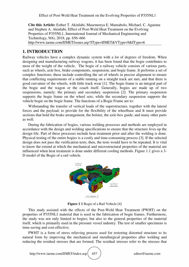
influenced when heat treatment is done under different cooling methods. Figure 1.1 gives a 3-
D model of the Bogie of a rail vehicle.
Figure 1 1 Bogie of a Rail Vehicle [4]
This study assisted with the effects of the Post-Weld Heat Treatment (PWHT) on the
properties of P355NL1 material that is used in the fabrication of bogie frames. Furthermore,
the study was not only limited to bogies; but also to the general properties of the material
itself, which is primarily used in the pressure vessel industry. The test of smaller specimens is
time-saving and cost-effective.
PWHT is a form of stress relieving process used for restoring distorted structure to its
natural form by improving the mechanical and metallurgical properties after welding and
reducing the residual stresses that are formed. The residual stresses refer to the stresses that
Esther T. Akinlabi, Masemenya E. Mamabolo, Michael. C. Agarana and Stephen A.
Akinlabi
http://www.iaeme.com/IJMET/index.asp 658 [email protected]
are present in an object, when no external forces are acting on it. This process is also used to
restore the macro-structure of the steel. The procedure and the conduction of PWHT is not
always done accurately; there are external factors that are sometimes introduced during the
procedure; which could influence the stress-relief process. The need for this procedure is
usually driven by a direct requirement within a fabrication, or by service environmental
concerns.
During fabrication, there are detailed codes regarding the fabrication requirements of
PWHT, which are aimed at reducing the sensitivity of the weld to brittle fracture; improving
the mechanical properties after welding and relaxing the residual stresses. The application of
PWHT is a critical evolution that would ensure that the work piece is correctly reconditioned;
thus, ensuring the most desirable levels of ductility, hardness and strength.
P355NL1 steel may be defined as wieldable fine-grain carbon low-alloy steel that is
delivered in a normalized condition; and it is intended for use in structures, such as pressure-
purpose vessels, where the notch toughness is of high importance. This material requires
PWHT after the component has been welded.
P355NL1 in its natural state has minimum yield strength of 355MPa, tensile strength that
is between 490 and 630 MPa and a minimum percentage elongation of 22%. The chemical
properties are shown in table 1-1, given by the maximum permitted element of each chemical.
Table 1 1 percentage by mass, maximum permitted [[5]]
C Si Mn P
0.18 0.5 1.1-1.7 0.025
S Al N Cr
0.015 0.02 0.012 0.3
Cu Mo Nb Ni
0.3 0.08 0.05 0.5
Ti V
0.03 0.1
PWHT has been found to improve the mechanical properties. This was verified by a study
that was conducted by AL-Alabi [[6]], who studied the effect of PWHT on the mechanical
properties and the microstructure of various metallic components. In the investigation, two
types of welded materials were used, namely: the AISI-1020 and AISI-410. Different PWHTs
were applied by varying the heating rate, the soaking temperature, the cooling rate and the
duration time during the process. The study showed that there were acceptable improvements
in the mechanical properties for certain PWHT schemes. In another study by Fadare et al.
[[7]], on the effect of heat treatment in the form of annealing, normalising, hardening, and
tempering on the metallurgical and mechanical properties of NST 37-2 steel. The sample was
heat treated in an electric oven at different temperatures and holding times and then cooled in
different media. The results showed that through heat treatment, the mechanical properties
can be altered or improved. The annealed samples with a dominating ferrite structure gave the
lowest tensile strength and hardness value and highest ductility and toughness value while the
samples that were hardened comprised of martensite and gave the highest tensile strength and
hardness value and lowest ductility and toughness value. Certain studies went as far as
incorporating heat input during welding, Chennaiah et al., [[8]] investigated the influence of
heat input and PWHT on the Microstructure and Mechanical properties in dissimilar (IS2062-
EN8) welded joints. The conclusions made from this study were that there are considerable
changes that occur in the mechanical properties for materials like IS2026; and because there
are slight variations in alloying elements, the physical properties may not change drastically.
Effect of Post-Weld Heat Treatment on the Evolving Properties of P355NL1
http://www.iaeme.com/IJMET/index.asp 659 [email protected]
The PWHT that is done on the P355NL1 material used on the bogie frame occurs in a
furnace that is large enough to accommodate the entire bogie frame [[9]]. The general
procedure involves the heating rate that starts from 204.4 °C per hour, divided by the
thickness, for thicknesses over 25.4 mm. The PWHT temperature should be set between 593
°C and 621 °C; while the holding time is done at about 2 hours for thicknesses over 25.4 mm;
with an extra fifteen minutes for every 25.4 mm [[9]].
The component is then allowed to leave the furnace and cool in the air. The challenges
encountered are that this procedure is not always done properly; and the effects on the
material are unknown [[9]].
The experiments featured a stress relieving process that was done in a furnace where three
different cooling schemes were employed for each sample. A control sample was left
untreated for comparison. Metallurgical tests and mechanical tests were done on these
samples and comparisons were made
2. EXPERIMENTAL PROCEDURE
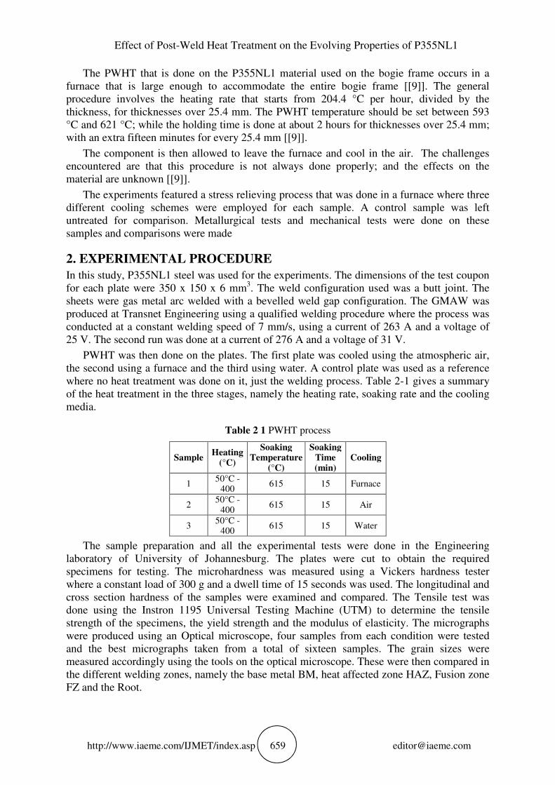
In this study, P355NL1 steel was used for the experiments. The dimensions of the test coupon
for each plate were 350 x 150 x 6 mm3. The weld configuration used was a butt joint. The
sheets were gas metal arc welded with a bevelled weld gap configuration. The GMAW was
produced at Transnet Engineering using a qualified welding procedure where the process was
conducted at a constant welding speed of 7 mm/s, using a current of 263 A and a voltage of
25 V. The second run was done at a current of 276 A and a voltage of 31 V.
PWHT was then done on the plates. The first plate was cooled using the atmospheric air,
the second using a furnace and the third using water. A control plate was used as a reference
where no heat treatment was done on it, just the welding process. Table 2-1 gives a summary
of the heat treatment in the three stages, namely the heating rate, soaking rate and the cooling
media.
Table 2 1 PWHT process
Sample Heating
(°C)
Soaking Temperature
(°C)
Soaking Time (min)
Cooling
1 50°C -
400 615 15 Furnace
2 50°C -
400 615 15 Air
3 50°C -
400 615 15 Water
The sample preparation and all the experimental tests were done in the Engineering
laboratory of University of Johannesburg. The plates were cut to obtain the required
specimens for testing. The microhardness was measured using a Vickers hardness tester
where a constant load of 300 g and a dwell time of 15 seconds was used. The longitudinal and
cross section hardness of the samples were examined and compared. The Tensile test was
done using the Instron 1195 Universal Testing Machine (UTM) to determine the tensile
strength of the specimens, the yield strength and the modulus of elasticity. The micrographs
were produced using an Optical microscope, four samples from each condition were tested
and the best micrographs taken from a total of sixteen samples. The grain sizes were
measured accordingly using the tools on the optical microscope. These were then compared in
the different welding zones, namely the base metal BM, heat affected zone HAZ, Fusion zone
FZ and the Root.
Esther T. Akinlabi, Masemenya E. Mamabolo, Michael. C. Agarana and Stephen A.
Akinlabi
http://www.iaeme.com/IJMET/index.asp 660 [email protected]
3. RESULTS AND DISCUSSIONS
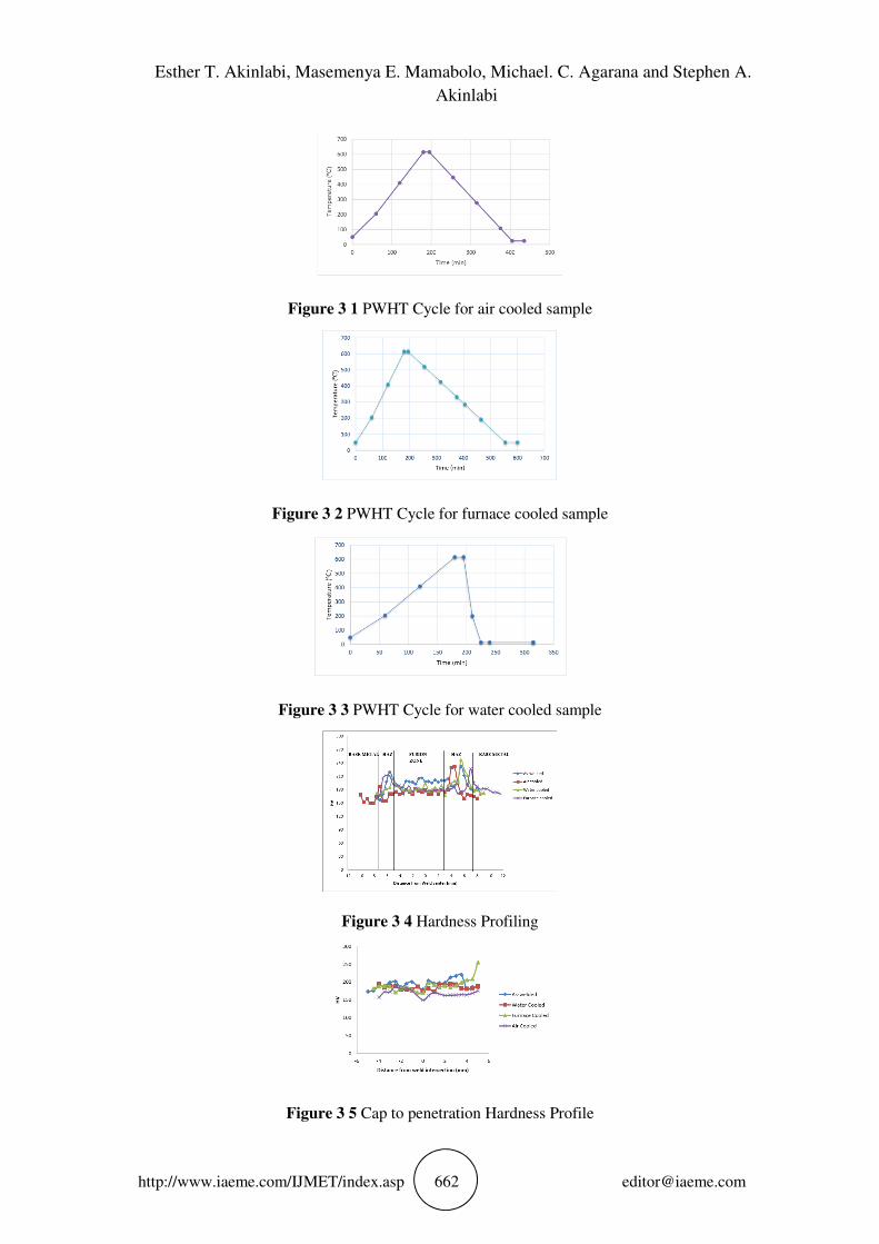
The results that were obtained in this study are presented and discussed in this section. Figure
3-1 through Figure 3-3 shows the process of PWHT represented by a plot of the temperature
vs time. The inclined steeply line shows the heating time while the declined line represents
the cooling time. The temperatures for the heating rate are assumed to be identical in all three
scenarios because the settings were not changed, thus the plates were assumed to have the
same readings at the recorded times. The cooling rate of the sample that was left in the
furnace was slower in comparison with the two that were air-cooled and water-cooled. The
distilled water that was used as a cooling medium had the lowest temperature; and the sample
cooled down more rapidly.
There were three samples from each of the conditions that were tested; the averages were
taken; and four graphs were produced. Figure 3-4 shows the hardness profiling of the
samples. The hardness profile was divided into three sections and plotted as shown in Figure
3-4. The HAZ showed to have a higher hardness than the base metal and the fusion zone. The
water-cooled sample showed the highest peak in the HAZ zone and the furnace at the lowest.
Contrary to this; the furnace cooled samples showed higher hardness values in the base metal.
The difference in hardness between the different zones is caused by the different
microstructures and prior processes that the material has endured such as the GMAW process
that introduces excessive heat in the HAZ zone and to the welding electrode itself. Figure 3-5
shows the variation in hardness from the cap of the weld to the penetration. The highest value
was recorded for the furnace-cooled sample at 255.3 HV, which was located at the root part of
the weld; while the lowest HV was recorded in the cap of the air sample at 149.6 HV, which
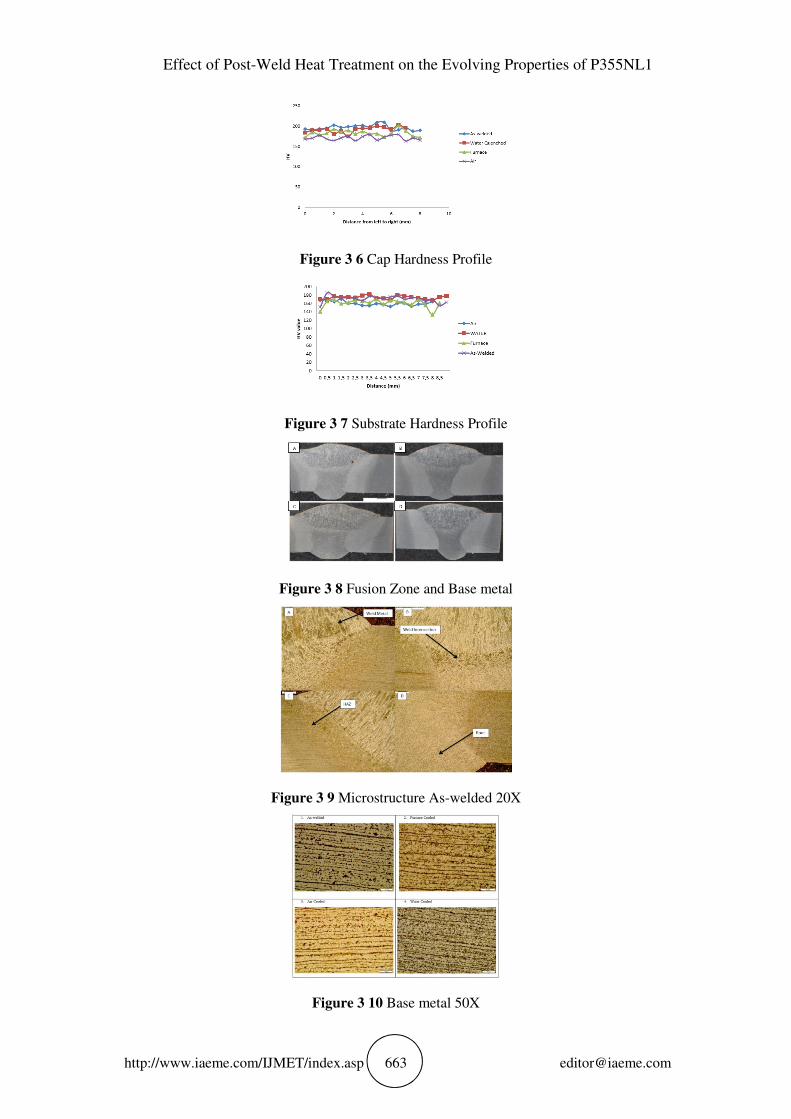
was located at the interface of the weld. The results that were taken for the cap-of-the-weld;
where the values recorded were taken from the left of the weld to the right. The lowest value
was recorded for the air-cooled sample at 163.7 HV; while the highest value was for the
untreated as-welded sample at 209 HV. The air samples generally have lower HVs on the cap.
The substrate showed hardness values that do not vary drastically throughout the measured
length. This part of the material endured the PWHT but was unaffected with the heat from the
welding process. It was found that the size of the weld metal is not consistent in the samples
that were cut. This may have been caused by several factors, such as the varied sizes of the
weld pool that were produced during the welding process. Figure 3-9 shows the arrangement
of the microstructure of the sample that was welded and not heat treated. The weld
intersection represents the area at which the two weld runs meet. The weld metal or fusion
zone is the area of the weld deposit. The BM in Figure 3-10 consists of a pearlite structure
with ferrite grain boundaries. This is the kind of microstructure that would be expected for
P355NL1 steel that has been heat-treated to a temperature that is less than the temperature at
which the steel enters the austenite region. The micrographs of the WM show long columnar
grains, which can be expected in this region for arc-welded carbon steel. Figure 3-11 shows
the micrograph of the WM. The microstructures that were produced in all the four cases were
Widmanstatten ferrite; there is also bainite that is present. The HAZ in Figure 3-12 seems to
have a martensitic microstructure. This is expected from this region, because during welding,
the HAZ is close to the cold BM; and after the weld has been deposited onto the metal, the
cooling rate is rapid. During the welding process, the cooling rate is not controlled; and
therefore, the rapid cooling occurs; since the weld metal is cooled by means of air. The root or
penetration of the weld seems to have an acicular ferrite and bainite microstructure. The
furnace-cooled and the water-cooled micrographs consist of larger ferrite grains, in
comparison with the samples that did not undergo any PWHT, or the one that was air- cooled.
Effect of Post-Weld Heat Treatment on the Evolving Properties of P355NL1
http://www.iaeme.com/IJMET/index.asp 661 [email protected]
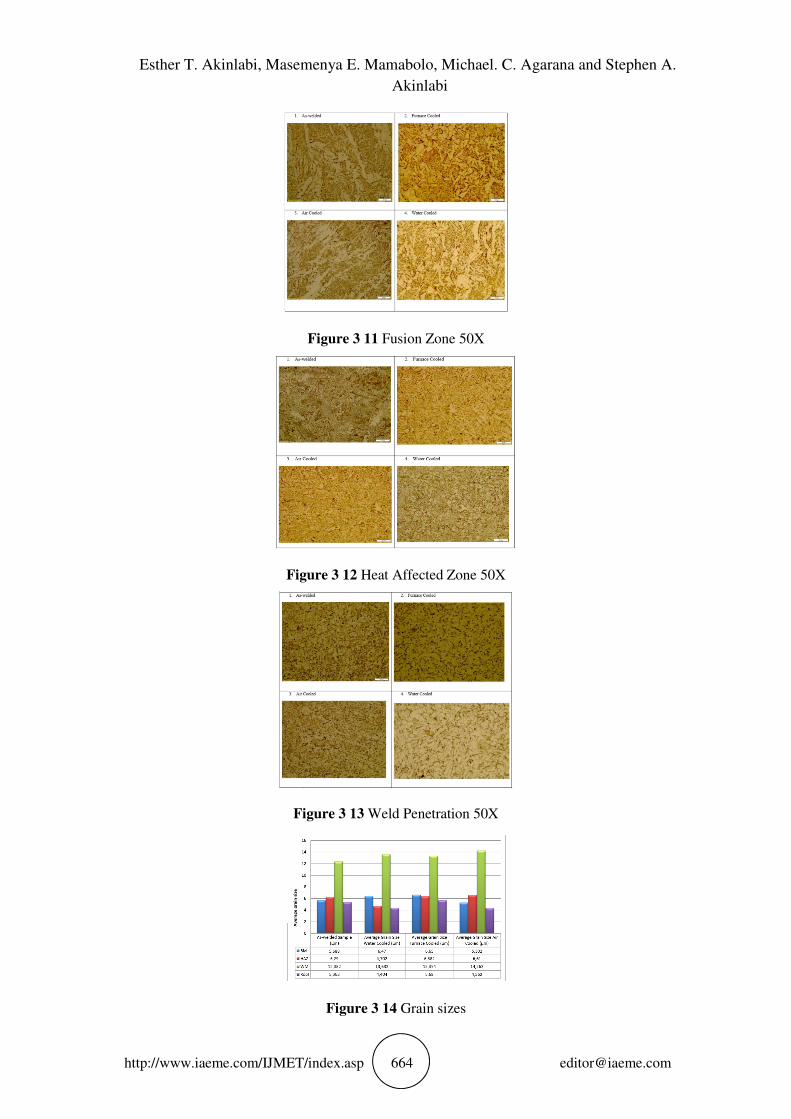
The grain sizes of the microstructure were determined using the average grain size method.
Five grains from each microstructure were measured by using the measuring tools that are
part of the optical microscope; then the average grain size was calculated. The grains are
measured in micrometers; the measurements were done for the BM, HAZ, WM and the root.
Figure 3-14 gives the average grain sizes for each condition and zone. From the results that
were recorded, it can be observed that the WM was measured to have bigger grain sizes in
comparison with the HAZ, BM and the root. The furnace-cooled sample had the largest grains
in the BM, with grains that averaged at 6.65 µm; while the air-cooled sample had the lowest
at 5.302 µm. In the HAZ area, the air-cooled sample had the highest grain size at 6.61; while
the water-cooled sample had the lowest at 4.702 µm. The largest grains in the WM were
obtained in the air-cooled sample at 14.262 µm; while the smallest were for the as-welded
sample at 12.382 µm. The root of the welded metal generally had smaller grains when
comparing it with the other zones, in this region; the water-cooled region had the smallest
grains at 4.404 µm; while the furnace cooled sample showed the highest grain size at 5.68
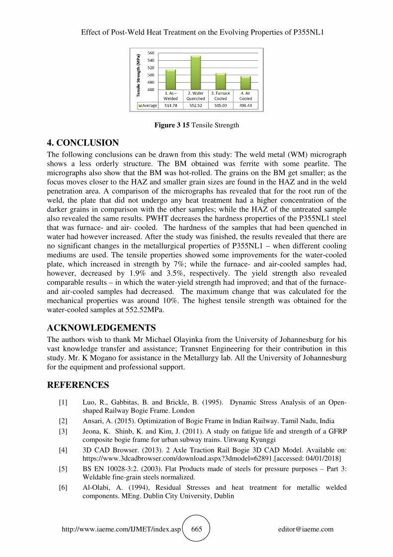
µm. This part of the paper gives the results that were obtained during the tensile test. Figure
3-15 shows the tensile strength of the four samples. Although the change in the tensile
properties of the material was not remarkable; it may be seen, the heat treatment and diverse
cooling rate has affected the tensile strength of the P355NL1 plates. treatment and diverse
cooling rate has affected the tensile strength of the P355NL1 plates. The results in Figure 3-15
show that the highest tensile strength was given by the specimen that was water-quenched
after PWHT. This was given at 552 MPa; while the lowest tensile strength was given by the
specimen that was cooled in the air, which was at 496.44 MPa. The specimen that was
untreated had the second-highest Tensile strength at 514.78 MPa. These results show that for
the tensile strength; the water-quenched specimen has improved, while those for the air-
cooled and the furnace-cooled had decreased. Figure 3-16 shows the yield strength of the
different samples. The effect of the heat treatment and the cooling media is evident. It is
evident from the results that the heat treatment and cooling rate increase or decrease the yield
strength of the material.
The yield strength results in Figure 3-16 revealed that the water-quenched samples have
the highest yield strength at 428.76 MPa; while the lowest was recorded for the furnace-
cooled sample at 356.94 MPa. These results reveal that when the as-welded sample is taken as
a reference point, then the furnace-cooled and the air-cooled samples had not increased in
terms of their yield strength The results of the Young’s modulus in Figure 3-17 were
calculated from the data that were received from the tensile-testing machine; and this was the
calculated slope of the stress-strain graph in the elastic region. The results show that the air-
cooled samples have the highest modulus of elasticity at 1598.78 MPa; although the modulus
of elasticity are in the same range; except for the lowest, which was obtained from the
furnace-cooled sample at 1287.55 MPa. These results were not as expected when in
comparison with the Modulus of elasticity that is specified for this specific material; in
contrast to this; a paper written by Fadare et al. [7]. yielded comparable results for the
modulus of elasticity. The difference in the tensile strength is not significant. This may be
caused by the fact that the samples were heated below the transformation temperature. The
difference that is encountered in the cooling rate may have influenced the variance in the
resistance of the metal to failure, yet not significantly. The point of fracture for all the samples
tested was on the part of the unaffected BM, which means that in this case, the residual
stresses encountered during the welding process could not have influenced the results
treatment and diverse cooling rate has affected the tensile strength of the P355NL1 plates.
Esther T. Akinlabi, Masemenya E. Mamabolo, Michael. C. Agarana and Stephen A.
Akinlabi
http://www.iaeme.com/IJMET/index.asp 662 [email protected]
Figure 3 1 PWHT Cycle for air cooled sample
Figure 3 2 PWHT Cycle for furnace cooled sample
Figure 3 3 PWHT Cycle for water cooled sample
Figure 3 4 Hardness Profiling
Figure 3 5 Cap to penetration Hardness Profile
Effect of Post-Weld Heat Treatment on the Evolving Properties of P355NL1
http://www.iaeme.com/IJMET/index.asp 663 [email protected]
Figure 3 6 Cap Hardness Profile
Figure 3 7 Substrate Hardness Profile
Figure 3 8 Fusion Zone and Base metal
Figure 3 9 Microstructure As-welded 20X
Figure 3 10 Base metal 50X
Esther T. Akinlabi, Masemenya E. Mamabolo, Michael. C. Agarana and Stephen A.
Akinlabi
http://www.iaeme.com/IJMET/index.asp 664 [email protected]
Figure 3 11 Fusion Zone 50X
Figure 3 12 Heat Affected Zone 50X
Figure 3 13 Weld Penetration 50X
Figure 3 14 Grain sizes
Effect of Post-Weld Heat Treatment on the Evolving Properties of P355NL1
http://www.iaeme.com/IJMET/index.asp 665 [email protected]
Figure 3 15 Tensile Strength
4. CONCLUSION
The following conclusions can be drawn from this study: The weld metal (WM) micrograph
shows a less orderly structure. The BM obtained was ferrite with some pearlite. The
micrographs also show that the BM was hot-rolled. The grains on the BM get smaller; as the
focus moves closer to the HAZ and smaller grain sizes are found in the HAZ and in the weld
penetration area. A comparison of the micrographs has revealed that for the root run of the
weld, the plate that did not undergo any heat treatment had a higher concentration of the
darker grains in comparison with the other samples; while the HAZ of the untreated sample
also revealed the same results. PWHT decreases the hardness properties of the P355NL1 steel
that was furnace- and air- cooled. The hardness of the samples that had been quenched in
water had however increased. After the study was finished, the results revealed that there are
no significant changes in the metallurgical properties of P355NL1 – when different cooling
mediums are used. The tensile properties showed some improvements for the water-cooled
plate, which increased in strength by 7%; while the furnace- and air-cooled samples had,
however, decreased by 1.9% and 3.5%, respectively. The yield strength also revealed
comparable results – in which the water-yield strength had improved; and that of the furnace-
and air-cooled samples had decreased. The maximum change that was calculated for the
mechanical properties was around 10%. The highest tensile strength was obtained for the
water-cooled samples at 552.52MPa.
ACKNOWLEDGEMENTS
The authors wish to thank Mr Michael Olayinka from the University of Johannesburg for his
vast knowledge transfer and assistance; Transnet Engineering for their contribution in this
study. Mr. K Mogano for assistance in the Metallurgy lab. All the University of Johannesburg
for the equipment and professional support.
REFERENCES
[1] Luo, R., Gabbitas, B. and Brickle, B. (1995). Dynamic Stress Analysis of an Open-
shaped Railway Bogie Frame. London
[2] Ansari, A. (2015). Optimization of Bogie Frame in Indian Railway. Tamil Nadu, India
[3] Jeona, K. Shinb, K. and Kim, J. (2011). A study on fatigue life and strength of a GFRP
composite bogie frame for urban subway trains. Uitwang Kyunggi
[4] 3D CAD Browser. (2013). 2 Axle Traction Rail Bogie 3D CAD Model. Available on:
https://www.3dcadbrowser.com/download.aspx?3dmodel=62891.[accessed: 04/01/2018]
[5] BS EN 10028-3:2. (2003). Flat Products made of steels for pressure purposes – Part 3:
Weldable fine-grain steels normalized.
[6] Al-Olabi, A. (1994), Residual Stresses and heat treatment for metallic welded
components. MEng. Dublin City University, Dublin
Esther T. Akinlabi, Masemenya E. Mamabolo, Michael. C. Agarana and Stephen A.
Akinlabi
http://www.iaeme.com/IJMET/index.asp 666 [email protected]
[7] Fadare D., Fadara T., Akanbi O. (2011). Effect of Heat Treatment on Mechanical
Properties of NST 31-2 Steel. University of Ibadan, Nigeria
[8] Chennaiah, M., Kumar, P. and Rao, K. (2016). Influence of Heat Input and PWHT on the
Microstructure and Mechanical Properties in Dissimilar (IS2062-EN8) Welded joints.
Anatapu, India.
[9] Shabtai I. (1997) Post Weld Heat Treatment Process no: P10D-EP13. GE Transportation
Systems. Boca Raton, Florida
[10] Dwivedi, D. (2014) Welding Engineering: Introduction to welding engineering.
Department of Mechanical and Industrial Engg, IIT Roorkee
[11] ASM International (2015). Handbook Committee, Standard Test Methods for Tension
Testing of Metallic Materials. West Conshohocken, United States of America. 99.
[12] ASM International. Handbook Committee (1997). ASM Handbook: Materials Selection
and Design. CRC Press. 100. ASTM E92-82 E3. (1997): Standard Test Method for
Vickers Hardness of Metallic Material ASTMs. Annual Book of ASTM Standards 101.
[13] ASTM A370 – 16. (2016): Standard Test Method and Definitions for Mechanical Testing
of Steel Products. Annual Book of ASTM Standards