Embed Size (px)
Citation preview
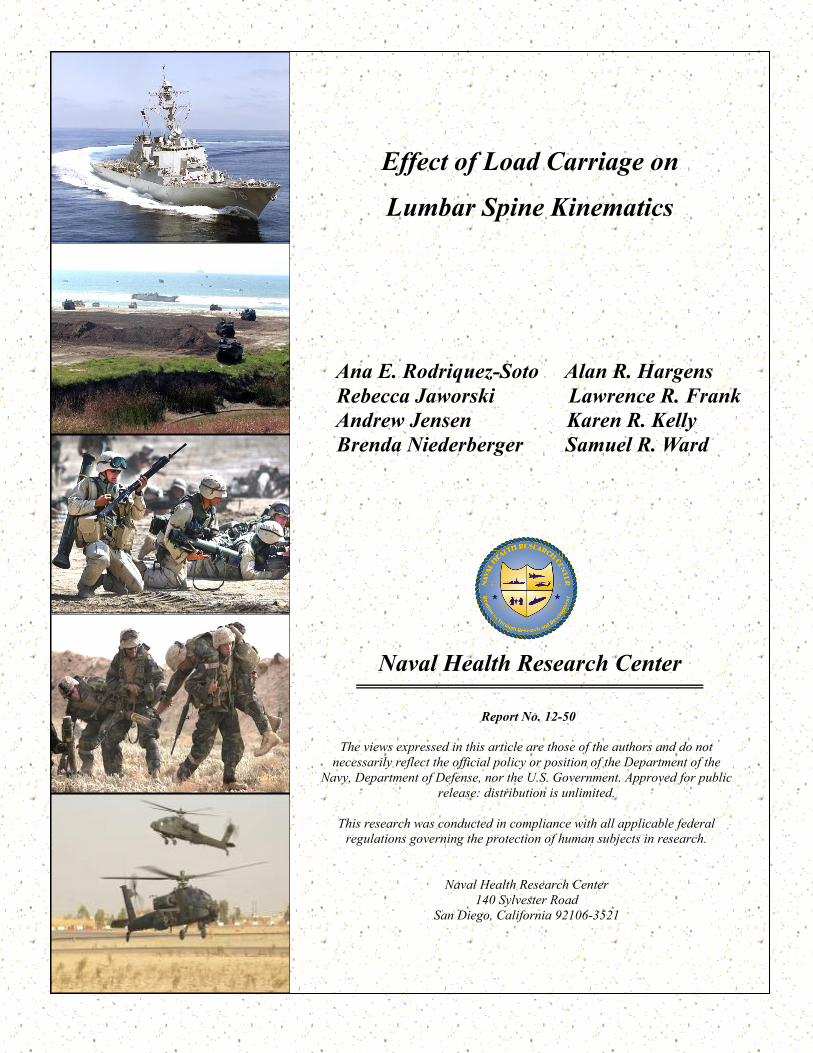
Naval Health Research Center
Effect of Load Carriage on
Lumbar Spine Kinematics
Ana E. Rodriquez-Soto Alan R. Hargens
Rebecca Jaworski Lawrence R. Frank
Andrew Jensen Karen R. Kelly
Brenda Niederberger Samuel R. Ward
Report No. 12-50
The views expressed in this article are those of the authors and do not
necessarily reflect the official policy or position of the Department of the
Navy, Department of Defense, nor the U.S. Government. Approved for public
release: distribution is unlimited.
This research was conducted in compliance with all applicable federal
regulations governing the protection of human subjects in research.
Naval Health Research Center
140 Sylvester Road
San Diego, California 92106-3521
BIOMECHANICS
SPINE Volume 38, Number 13, pp E783–E791©2013, Lippincott Williams & Wilkins
Spine www.spinejournal.com E783
Effect of Load Carriage on Lumbar Spine Kinematics
Ana E. Rodríguez-Soto , BSc , * Rebecca Jaworski , PhD , ¶ ** Andrew Jensen , MS , ¶ � Brenda Niederberger , MA , ¶ Alan R. Hargens , PhD , ‡ Lawrence R. Frank , PhD , * § Karen R. Kelly , PhD , ¶ � and Samuel R. Ward , PT, PhD * † ‡
Study Design. Feasibility study on the acquisition of lumbar spine kinematic data from upright magnetic resonance images obtained under heavy load carrying conditions. Objective. To characterize the effect of the load on spinal kinematics of active Marines under typical load carrying conditions from a macroscopic and lumbar-level approach in active-duty US Marines. Summary of Background Data. Military personnel carry heavy loads of up to 68 kg depending on duty position and nature of the mission or training; these loads are in excess of the recommended assault loads. Performance and injury associated with load carriage have been studied; however, knowledge of lumbar spine kinematic changes is still not incorporated into training. These data would provide guidance for setting load and duration limits and a tool to investigate the potential contribution of heavy load carrying on lumbar spine pathologies. Methods. Sagittal T2 magnetic resonance images of the lumbar spine were acquired on a 0.6-T upright magnetic resonance imaging scanner for 10 active-duty Marines. Each Marine was scanned without load (UN1), immediately after donning load (LO2), after 45 minutes of standing (LO3) and walking (LO4) with load, and after 45 minutes of side-lying recovery (UN5). Custom-made software was used to measure whole spine angles, intervertebral angles, and regional disc heights (L1–S1). Repeated measurements analysis of
Military personnel carry heavy loads of up to 68 kg (149.9 lbs) depending on duty position and nature of the mission. 1 For example, fi ghting loads range
between 24 and 37 kg (52.9 and 81.5 lbs), while approach march loads are carried in more prolonged operations and range from 50 to 67 kg (110.2 and 147.7 lbs). 2 These loads are well in excess from the recommendation of load limits of 22 kg (or 30% of body weight [BW]) and 33 kg (or 45% of BW]) for fi ghting and march loads, respectively. 3 Load limits have been extensively studied in terms of optimum energy expen-diture, 4 , 5 situational awareness, and responsiveness, 6 resulting in several load carriage system (LCS) confi gurations. 7 In gen-eral, the LCS backpack confi guration is preferred among the military because of the proximity of the load to the center of mass of the system compared with other LCS confi gura-tions. 8 , 9 Despite these efforts, heavy load carriage in the mili-tary population has been associated with lower back pain. 10 – 12
The kinematic behavior of the lumbar spine while carrying load using a backpack confi guration has been previously stud-ied in both in civilian and military populations. 7 , 13 – 18 The major-ity of these studies have used optical markers 14 – 16 , 18 and ground force plates 7 , 18 , 19 to measure body positioning and ground reac-tion forces. These methods approach the lumbar spine from a macroscopic perspective, as a unit that joins the upper and lower bodies. To investigate the lumbar spine in greater detail, other studies have used noninvasive imaging methods, such as
From the Departments of * Bioengineering † Radiology, and ‡ Orthopaedic Surgery, University of California San Diego, La Jolla, CA ; § Veterans Administration Medical Center, San Diego, CA ; ¶ Department of Warfi ghter Performance, Naval Health Research Center, San Diego, CA ; � Department of Exercise and Nutritional Sciences, San Diego State University, San Diego, CA; and ** Marine Expeditionary Rifl e Squad, Marine Corp System Command, Quantico, VA.
Acknowledgment date: December 17, 2012. First revision date: February 8, 2013. Acceptance date: February 21, 2013.
The views expressed in this material are those of the authors, and do not refl ect the offi cial policy or position of the US Government, Department of Defense, US Navy, or US Marine Corp.
The manuscript submitted does not contain information about medical device(s)/drug(s).
Bureau of Medicine and Surgery-Wounded Ill and Injured program (BUMED-WII42, WU61016, US ARMY RDECOM N6311610MP00182) funds were received to support this work.
Relevant fi nancial activities outside the submitted work: support for travel to meetings and grants pending.
Address correspondence and reprint requests to Samuel R. Ward, PT, PhD, Department of Radiology, Orthopaedic Surgery, and Bioengineering, 9500 Gilman Drive (0610), La Jolla, CA 92093; E-mail: [email protected]
variance and post hoc Sidak tests were used to identify signifi cant differences between tasks ( α = 0.05). Results. The position of the spine was signifi cantly ( P < 0.0001) more horizontal relative to the external reference frame and lordosis was reduced during all tasks with load. Superior levels became more lordotic, whereas inferior levels became more kyphotic. Heavy load induced lumbar spine fl exion and only anterior disc and posterior intervertebral disc height changes were observed. All kinematic variables returned to baseline levels after 45 minutes of side-lying recovery. Conclusion. Superior and inferior lumbar levels showed different kinematic behaviors under heavy load carrying conditions. These fi ndings suggest a postural, lumbar fl exion strategy aimed at centralizing a heavy posterior load over the base of support. Key words: low back pain , backpack , military , load carriage , MRI , upright MRI , lumbar spine kinematics. Spine 2013 ;38:E783–E791
DOI: 10.1097/BRS.0b013e3182913e9f
Copyright © 2013 Lippincott Williams & Wilkins. Unauthorized reproduction of this article is prohibited.
BRS205569.indd E783BRS205569.indd E783 13/05/13 7:19 PM13/05/13 7:19 PM

BIOMECHANICS Effect of Load Carriage on Lumbar Spine Kinematics • Rodríguez-Soto et al
E784 www.spinejournal.com June 2013
magnetic resonance imaging (MRI), 20 , 21 computed tomography (CT), 22 and myelography. 23 In these techniques the subject is lying in supine position as images are acquired, consequently, researchers have attempted to simulate upright and other func-tional positions by applying axial load to the subject with dif-ferent devices. 20 , 21 However, it has been shown that the kine-matic data obtained in this setting do not refl ect the state of the lumbar spine in the upright position due to alterations in bone-muscle interactions, spine length and curvature, spinal canal cross-sectional area, and regional intervertebral disc (IVD) heights. 22 , 24 , 25 To overcome this situation and allow imaging of the body in realistic functional positions, technologies such as upright MRI 25 and dual-plane fl uoroscopy 26 were developed. Measurements generated from these technologies take into account gravitational and weight-bearing effects, producing a more accurate description of the kinematic state of the spine in real-life situations. 27 To date, kinematic variables such as spine curvature, lumbar spine lordosis, and IVD compressibility have been measured in both young 17 and adult 13 populations using upright MRI. However, these data cannot be applied to the military population for 3 main reasons. First, the magnitude of the carried loads is small compared with those in a military context; in most studies load ranges between 15% and 30% of BW, 13 , 17 while soldiers carry up to 80% of BW. 2 Second, the length of exposure to load in these studies is in the range of a few minutes, whereas military marches extend for several hours. 28 Finally, a fundamental aspect of a soldier’s basic train-ing consists of progressively increasing the amount of load and march distance. 3 , 28 This training has been shown to have an impact on the endurance and performance of soldiers, therefore the kinematic behavior data cannot be compared with that of the civilian population. 16 , 29 Demonstrating that kinematic data of the lumbar spine can be obtained under heavy load carrying conditions would provide guidance for setting load and dura-tion limits and provide a research tool to investigate the poten-tial contribution of heavy load carrying to lower back pain.
The purpose of this study was to measure the kinematic behavior of the lumbar spine from both a regional and local (level-dependent) approach in active-duty US Marines while carrying heavy load. This study also investigated the length of exposure and activity that induced signifi cant changes in the kinematic behavior of the overall lumbar spine and func-tional spinal units. We hypothesized that IVD compression and lumbar lordosis increased with load and time of exposure through the lumbar spine.
MATERIALS AND METHODS
Subjects Ten male Marines from the Marine Corps Base Camp Pend-leton, with no history of lower back issues volunteered to
participate in this study. The University of California, San Diego and Naval Health Research Center Institutional Review Boards approved this pilot study, and all volunteers gave oral and written informed consent.
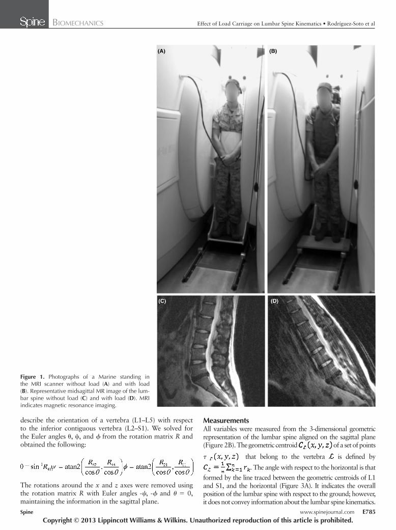
Imaging Marines were scanned using a 0.6-T MRI scanner (Upright MRI, Fonar Corporation, Melville, NY) and a planar RF coil. A brace was used to place the coil behind the volunteers’ back at the lumbar spine (L1–S1) level while standing ( Figure 1A ). The brace was tight enough to keep the coil in place and avoid as much as possible any alteration of the volun-teer’s natural standing position. A 3-plane localizer and sag-ittal T2 weighted images (repetition time = 610 mS, echo time = 17 mS, fi eld of view = 24 cm, 210 × 210 acquisition matrix, 4-mm slice thickness, no gap, scan duration 2 min) were acquired.
Load-Carrying Tasks With the purpose of measuring kinematic changes in the lum-bar spine under load-carrying conditions, Marines performed a series of tasks with load and were scanned at different time points in one session ( Figure 1B ). Each Marine was scanned a total of 5 times in the following order: standing without load (UN1), immediately after donning load (LO2), after 45 minutes of standing with load (LO3), after 45 minutes of walking on a treadmill at 3 mph with load (LO4), and after a recovery period of 45 minutes side-lying (UN5), half the time on each side ( Figure 1 ). The total carrying load was 112 lbs (50.8 kg) including body armor and an improved load-bearing equipment backpack fi lled with tile. During standing tasks, Marines were instructed not to lean on surfaces ( i.e ., walls and chairs), but moving around the scanner console room was permitted. It was not indicated to our volunteers how to stand during scans to avoid the alteration of their natural standing position.
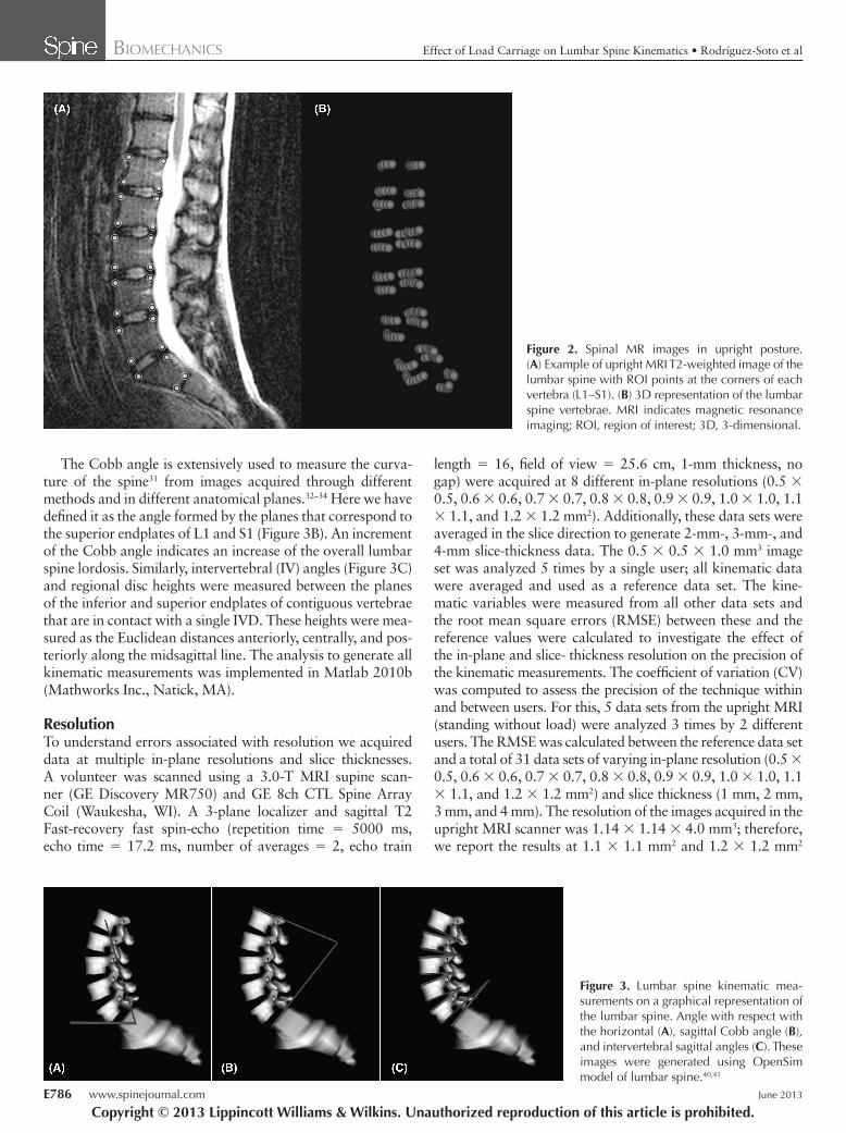
Data Analyses A set of points was manually placed at the corners of the each vertebra on the images acquired in the upright MR scanner using the region of interest point tool available in Osirix (Pixmeo, Geneva, Switzerland) ( Figure 2A ). 30 The location of the seed points were used to fi t planes to the inferior and supe-rior endplates of each vertebra . To compare sagittal mea-surements between Marines, due to the differences in standing positions, Procrustes analysis was used to fi nd the rotation matrix R between the inferior and superior vertebrae contigu-ous vertebrae with the inferior vertebra as reference. The rota-tion matrix R follows the x - y - z convention defi ned as follows: where ψ , θ , and ϕ are the rotations in radians around the x , y , and z axes, respectively. These are the Euler angles that
R11
Copyright © 2013 Lippincott Williams & Wilkins. Unauthorized reproduction of this article is prohibited.
BRS205569.indd E784BRS205569.indd E784 13/05/13 7:19 PM13/05/13 7:19 PM
BIOMECHANICS Effect of Load Carriage on Lumbar Spine Kinematics • Rodríguez-Soto et al
Spine www.spinejournal.com E785
describe the orientation of a vertebra (L1–L5) with respect to the inferior contiguous vertebra (L2–S1). We solved for the Euler angles θ , ψ , and ϕ from the rotation matrix R and obtained the following:
The rotations around the x and z axes were removed using the rotation matrix R with Euler angles - ψ , -ϕ and θ = 0, maintaining the information in the sagittal plane.
Measurements All variables were measured from the 3-dimensional geometric representation of the lumbar spine aligned on the sagittal plane ( Figure 2B ). The geometric centroid of a set of points
τ that belong to the vertebra is defi ned by
. The angle with respect to the horizontal is that
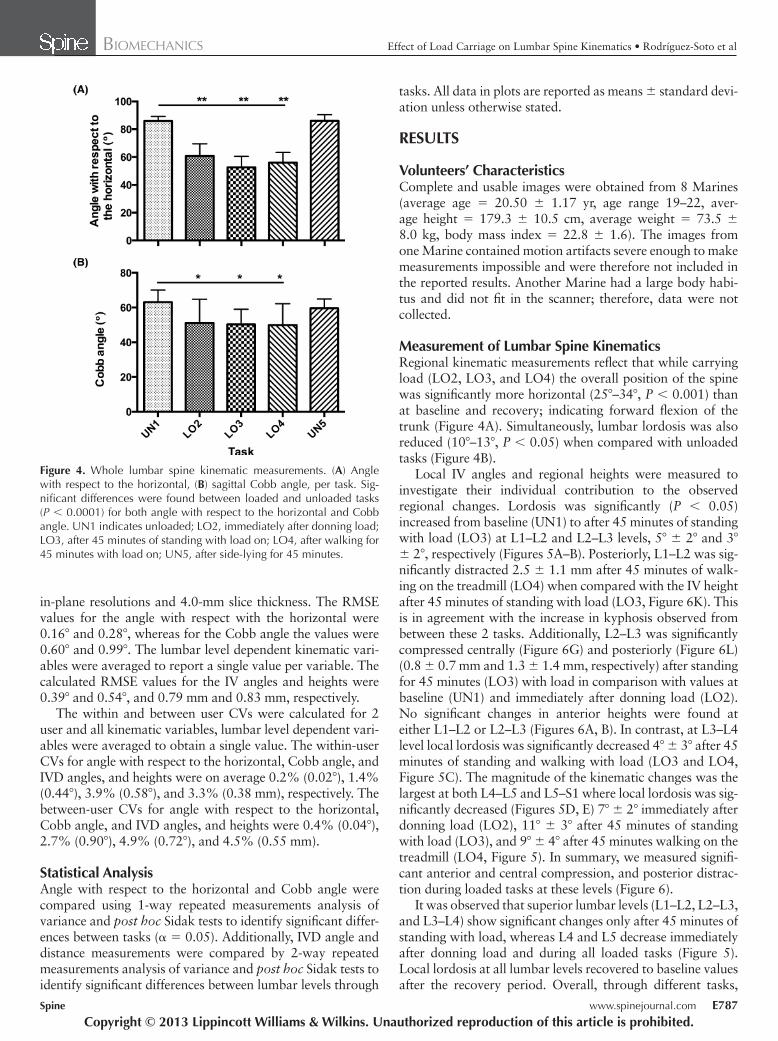
formed by the line traced between the geometric centroids of L1 and S1, and the horizontal ( Figure 3A ). It indicates the overall position of the lumbar spine with respect to the ground; however, it does not convey information about the lumbar spine kinematics.
Figure 1. Photographs of a Marine standing in the MRI scanner without load (A) and with load (B). Representative midsagittal MR image of the lum-bar spine without load (C) and with load (D). MRI indicates magnetic resonance imaging.
Copyright © 2013 Lippincott Williams & Wilkins. Unauthorized reproduction of this article is prohibited.
BRS205569.indd E785BRS205569.indd E785 13/05/13 7:19 PM13/05/13 7:19 PM
BIOMECHANICS Effect of Load Carriage on Lumbar Spine Kinematics • Rodríguez-Soto et al
E786 www.spinejournal.com June 2013
length = 16, fi eld of view = 25.6 cm, 1-mm thickness, no gap) were acquired at 8 different in-plane resolutions (0.5 × 0.5, 0.6 × 0.6, 0.7 × 0.7, 0.8 × 0.8, 0.9 × 0.9, 1.0 × 1.0, 1.1 × 1.1, and 1.2 × 1.2 mm 2 ). Additionally, these data sets were averaged in the slice direction to generate 2-mm-, 3-mm-, and 4-mm slice-thickness data. The 0.5 × 0.5 × 1.0 mm 3 image set was analyzed 5 times by a single user; all kinematic data were averaged and used as a reference data set. The kine-matic variables were measured from all other data sets and the root mean square errors (RMSE) between these and the reference values were calculated to investigate the effect of the in-plane and slice- thickness resolution on the precision of the kinematic measurements. The coeffi cient of variation (CV) was computed to assess the precision of the technique within and between users. For this, 5 data sets from the upright MRI (standing without load) were analyzed 3 times by 2 different users. The RMSE was calculated between the reference data set and a total of 31 data sets of varying in-plane resolution (0.5 × 0.5, 0.6 × 0.6, 0.7 × 0.7, 0.8 × 0.8, 0.9 × 0.9, 1.0 × 1.0, 1.1 × 1.1, and 1.2 × 1.2 mm 2 ) and slice thickness (1 mm, 2 mm, 3 mm, and 4 mm). The resolution of the images acquired in the upright MRI scanner was 1.14 × 1.14 × 4.0 mm 3 ; therefore, we report the results at 1.1 × 1.1 mm 2 and 1.2 × 1.2 mm 2
The Cobb angle is extensively used to measure the curva-ture of the spine 31 from images acquired through different methods and in different anatomical planes. 32 – 34 Here we have defi ned it as the angle formed by the planes that correspond to the superior endplates of L1 and S1 ( Figure 3B ). An increment of the Cobb angle indicates an increase of the overall lumbar spine lordosis. Similarly, intervertebral (IV) angles ( Figure 3C ) and regional disc heights were measured between the planes of the inferior and superior endplates of contiguous vertebrae that are in contact with a single IVD. These heights were mea-sured as the Euclidean distances anteriorly, centrally, and pos-teriorly along the midsagittal line. The analysis to generate all kinematic measurements was implemented in Matlab 2010b (Mathworks Inc., Natick, MA).
Resolution To understand errors associated with resolution we acquired data at multiple in-plane resolutions and slice thicknesses. A volunteer was scanned using a 3.0-T MRI supine scan-ner (GE Discovery MR750) and GE 8ch CTL Spine Array Coil (Waukesha, WI). A 3-plane localizer and sagittal T2 Fast-recovery fast spin-echo (repetition time = 5000 ms, echo time = 17.2 ms, number of averages = 2, echo train
Figure 2. Spinal MR images in upright posture. (A) Example of upright MRI T2-weighted image of the lumbar spine with ROI points at the corners of each vertebra (L1–S1). (B) 3D representation of the lumbar spine vertebrae. MRI indicates magnetic resonance imaging; ROI, region of interest; 3D, 3-dimensional.
Figure 3. Lumbar spine kinematic mea-surements on a graphical representation of the lumbar spine. Angle with respect with the horizontal (A), sagittal Cobb angle (B), and intervertebral sagittal angles (C). These images were generated using OpenSim model of lumbar spine. 40 , 41
Copyright © 2013 Lippincott Williams & Wilkins. Unauthorized reproduction of this article is prohibited.
BRS205569.indd E786BRS205569.indd E786 13/05/13 7:19 PM13/05/13 7:19 PM
BIOMECHANICS Effect of Load Carriage on Lumbar Spine Kinematics • Rodríguez-Soto et al
Spine www.spinejournal.com E787
tasks. All data in plots are reported as means ± standard devi-ation unless otherwise stated.
RESULTS
Volunteers’ Characteristics Complete and usable images were obtained from 8 Marines (average age = 20.50 ± 1.17 yr, age range 19–22, aver-age height = 179.3 ± 10.5 cm, average weight = 73.5 ± 8.0 kg, body mass index = 22.8 ± 1.6). The images from one Marine contained motion artifacts severe enough to make measurements impossible and were therefore not included in the reported results. Another Marine had a large body habi-tus and did not fi t in the scanner; therefore, data were not collected.
Measurement of Lumbar Spine Kinematics Regional kinematic measurements refl ect that while carrying load (LO2, LO3, and LO4) the overall position of the spine was signifi cantly more horizontal (25 ° –34 ° , P < 0.001) than at baseline and recovery; indicating forward fl exion of the trunk ( Figure 4A ). Simultaneously, lumbar lordosis was also reduced (10 ° –13 ° , P < 0.05) when compared with unloaded tasks ( Figure 4B ).
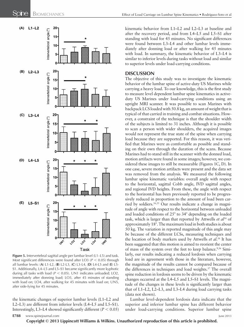
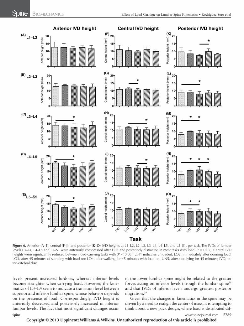
Local IV angles and regional heights were measured to investigate their individual contribution to the observed regional changes. Lordosis was signifi cantly ( P < 0.05) increased from baseline (UN1) to after 45 minutes of standing with load (LO3) at L1–L2 and L2–L3 levels, 5 ° ± 2 ° and 3 ° ± 2 ° , respectively ( Figures 5A–B ). Posteriorly, L1–L2 was sig-nifi cantly distracted 2.5 ± 1.1 mm after 45 minutes of walk-ing on the treadmill (LO4) when compared with the IV height after 45 minutes of standing with load (LO3, Figure 6K ). This is in agreement with the increase in kyphosis observed from between these 2 tasks. Additionally, L2–L3 was signifi cantly compressed centrally ( Figure 6G ) and posteriorly ( Figure 6L ) (0.8 ± 0.7 mm and 1.3 ± 1.4 mm, respectively) after standing for 45 minutes (LO3) with load in comparison with values at baseline (UN1) and immediately after donning load (LO2). No signifi cant changes in anterior heights were found at either L1–L2 or L2–L3 ( Figures 6A, B ). In contrast, at L3–L4 level local lordosis was signifi cantly decreased 4 ° ± 3 ° after 45 minutes of standing and walking with load (LO3 and LO4, Figure 5C ). The magnitude of the kinematic changes was the largest at both L4–L5 and L5–S1 where local lordosis was sig-nifi cantly decreased ( Figures 5D, E ) 7 ° ± 2 ° immediately after donning load (LO2), 11 ° ± 3 ° after 45 minutes of standing with load (LO3), and 9 ° ± 4 ° after 45 minutes walking on the treadmill (LO4, Figure 5 ). In summary, we measured signifi -cant anterior and central compression, and posterior distrac-tion during loaded tasks at these levels ( Figure 6 ).
It was observed that superior lumbar levels (L1–L2, L2–L3, and L3–L4) show signifi cant changes only after 45 minutes of standing with load, whereas L4 and L5 decrease immediately after donning load and during all loaded tasks ( Figure 5 ). Local lordosis at all lumbar levels recovered to baseline values after the recovery period. Overall, through different tasks,
in-plane resolutions and 4.0-mm slice thickness. The RMSE values for the angle with respect with the horizontal were 0.16 ° and 0.28 ° , whereas for the Cobb angle the values were 0.60 ° and 0.99 ° . The lumbar level dependent kinematic vari-ables were averaged to report a single value per variable. The calculated RMSE values for the IV angles and heights were 0.39 ° and 0.54 ° , and 0.79 mm and 0.83 mm, respectively.
The within and between user CVs were calculated for 2 user and all kinematic variables, lumbar level dependent vari-ables were averaged to obtain a single value. The within-user CVs for angle with respect to the horizontal, Cobb angle, and IVD angles, and heights were on average 0.2% (0.02 ° ), 1.4% (0.44 ° ), 3.9% (0.58 ° ), and 3.3% (0.38 mm), respectively. The between-user CVs for angle with respect to the horizontal, Cobb angle, and IVD angles, and heights were 0.4% (0.04 ° ), 2.7% (0.90 ° ), 4.9% (0.72 ° ), and 4.5% (0.55 mm).
Statistical Analysis Angle with respect to the horizontal and Cobb angle were compared using 1-way repeated measurements analysis of variance and post hoc Sidak tests to identify signifi cant differ-ences between tasks ( α = 0.05). Additionally, IVD angle and distance measurements were compared by 2-way repeated measurements analysis of variance and post hoc Sidak tests to identify signifi cant differences between lumbar levels through
Figure 4. Whole lumbar spine kinematic measurements. (A) Angle with respect to the horizontal, (B) sagittal Cobb angle, per task. Sig-nifi cant differences were found between loaded and unloaded tasks ( P < 0.0001) for both angle with respect to the horizontal and Cobb angle. UN1 indicates unloaded; LO2, immediately after donning load; LO3, after 45 minutes of standing with load on; LO4, after walking for 45 minutes with load on; UN5, after side-lying for 45 minutes.
Copyright © 2013 Lippincott Williams & Wilkins. Unauthorized reproduction of this article is prohibited.
BRS205569.indd E787BRS205569.indd E787 13/05/13 7:19 PM13/05/13 7:19 PM
BIOMECHANICS Effect of Load Carriage on Lumbar Spine Kinematics • Rodríguez-Soto et al
E788 www.spinejournal.com June 2013
kinematic behavior from L1–L2 and L2–L3 at baseline and after the recovery period, and from L4–L5 and L5–S1 after standing with load for 45 minutes. No signifi cant differences were found between L3–L4 and other lumbar levels imme-diately after donning load or after walking for 45 minutes with load. In summary, the kinematic behavior of L3–L4 is similar to inferior levels during tasks without load and similar to superior levels under load-carrying conditions.
DISCUSSION The objective of this study was to investigate the kinematic behavior of the lumbar spine of active-duty US Marines while carrying a heavy load. To our knowledge, this is the fi rst study to measure level dependent lumbar spine kinematics in active-duty US Marines under load-carrying conditions using an upright MRI scanner. It was possible to scan Marines with backpack LCS loaded with 50.8 kg, an amount of weight that is typical of that carried in training and combat situations. How-ever, a constraint of the technique is that the shoulder width of the subjects is limited to 31 inches. Although it is possible to scan a person with wider shoulders, the acquired images would not represent the true state of the spine when carrying load because they are supported. For this reason, it was veri-fi ed that Marines were as comfortable as possible and stand-ing on their own through the duration of the scans. Because Marines had to stand still in the scanner with the donned load, motion artifacts were found in some images; however, we con-sidered these images to still be measurable ( Figures 1C, D ). In one case, severe motion artifacts were present and the data set was removed from the analysis. We measured the following lumbar spine kinematic variables: overall angle with respect to the horizontal, sagittal Cobb angle, IVD sagittal angles, and regional IVD heights. From these, the angle with respect to the horizontal has been previously reported to be progres-sively reduced in proportion to the amount of load been car-ried by soldiers. 16 , 35 Our results indicate a change in magni-tude of angle with respect to the horizontal between unloaded and loaded conditions of 25 ° to 34 ° depending on the loaded task, which is larger than that reported by Attwells et al 16 of approximately 18 ° . The maximum load in both studies is about 50 kg. The variation in reported magnitude of this angle may be because of the different LCSs, measuring techniques and the location of body markers used by Attwells et al . 16 It has been suggested that this motion is aimed to reorient the center of mass of the system over the feet to keep balance. 9 , 36 Simi-larly, our results indicating a reduced lordosis when carrying load are in agreement with those in the literature, however, the magnitude of the results cannot be compared because of the differences in techniques and load weights. 37 The overall spine reduction in lordosis seems to be driven by the kinematic changes occurred at the L4–L5 and L5–S1 levels. The magni-tude of the changes in these levels is signifi cantly larger than that of L1–L2, L2–L3, and L3–L4 during load carrying tasks (data not shown).
Lumbar level-dependent lordosis data indicate that the superior and inferior lumbar spine has different behavior under load-carrying conditions. Superior lumbar spine
the kinematic changes of superior lumbar levels (L1–L2 and L2–L3) are different from inferior levels (L4–L5 and L5–S1). Interestingly, L3–L4 showed signifi cantly different ( P < 0.05)
Figure 5. Intervertebral sagittal angle per lumbar level (L1–L5) and task. Most signifi cant differences were found after LO3 ( P < 0.05) through all lumbar levels: (A) L1-L2, (B) L2-L3, (C) L3-L4, (D) L4-L5 and (E) L5-S1. Additionally, L4–L5 and L5–S1 became signifi cantly more kyphotic during all tasks with load ( P < 0.05). UN1 indicates unloaded; LO2, immediately after donning load; LO3, after 45 minutes of standing with load on; LO4, after walking for 45 minutes with load on; UN5, after side-lying for 45 minutes.
Copyright © 2013 Lippincott Williams & Wilkins. Unauthorized reproduction of this article is prohibited.
BRS205569.indd E788BRS205569.indd E788 13/05/13 7:19 PM13/05/13 7:19 PM
BIOMECHANICS Effect of Load Carriage on Lumbar Spine Kinematics • Rodríguez-Soto et al
Spine www.spinejournal.com E789
in the lower lumbar spine might be related to the greater forces acting on inferior levels through the lumbar spine 38 and that IVDs of inferior levels undergo greatest posterior migration. 39
Given that the changes in kinematics in the spine may be driven by a need to realign the center of mass, it is tempting to think about a new pack design, where load is distributed dif-
levels present increased lordosis, whereas inferior levels become straighter when carrying load. However, the kine-matics of L3–L4 seem to indicate a transition level between superior and inferior lumbar spine, whose behavior depends on the presence of load. Correspondingly, IVD height is anteriorly decreased and posteriorly increased in inferior lumbar levels. The fact that most signifi cant changes occur
Figure 6. Anterior (A–E), central (F–J), and posterior (K–O) IVD heights at L1–L2, L2–L3, L3–L4, L4–L5, and L5–S1, per task. The IVDs of lumbar levels L3–L4, L4–L5 and L5–S1 were anteriorly compressed after LO3 and posteriorly distracted in most tasks with load ( P < 0.05). Central IVD heights were signifi cantly reduced between load-carrying tasks with ( P < 0.05). UN1 indicates unloaded; LO2, immediately after donning load; LO3, after 45 minutes of standing with load on; LO4, after walking for 45 minutes with load on; UN5, after side-lying for 45 minutes; IVD, in-tervertebral disc.
Copyright © 2013 Lippincott Williams & Wilkins. Unauthorized reproduction of this article is prohibited.
BRS205569.indd E789BRS205569.indd E789 13/05/13 7:19 PM13/05/13 7:19 PM
BIOMECHANICS Effect of Load Carriage on Lumbar Spine Kinematics • Rodríguez-Soto et al
E790 www.spinejournal.com June 2013
such as children 17 and females 40 the magnitude of the changes observed are greater than those observed here. Inversely, in an older population with known decreased range of motion, 41 the magnitude of level-dependent kinematics is expected to decrease, therefore compromising the capacity of the lumbar spine to accommodate kinematic changes. In terms of body habitus, if our speculation that kinematic changes are driven by the need to maintain body center of mass, then obese indi-viduals may be in a more lordotic posture without load and might lean forward less when load is applied.
CONCLUSION In conclusion, we measured the kinematic behavior of the lumbar spine of active-duty US Marines while carrying heavy loads. Our results suggest that when Marines carry load and lean forward the superior functional units of the lumbar spine act differently than the inferior units. Locally, the superior levels go into lordosis, whereas inferior levels become more kyphotic. The contribution of each intervertebral level is refl ected in lumbar spine fl exion and reduced lordosis during load-carrying tasks. Moreover, the anterior disc region of infe-rior lumbar levels is compressed, whereas the posterior disc region is distracted leading to immediate kinematic changes after donning load. This is in contrast to superior lumbar lev-els, which undergo changes in their kinematic behavior dur-ing longer load duration. Future research is needed to inves-tigate how this behavior over time affects health outcomes related to lower back pain and degeneration in military and civilian populations.
ferently between the front and back. However, previous work in this fi eld has demonstrated that distributing the weight toward the front of the trunk is uncomfortable and interferes breathing and operational use of the arms. 8
LIMITATIONS Upright MRI has the advantage of acquiring images while sub-jects are in functional and relevant positions. However, this system also has characteristics that impose limitations on this study. Although this technique does not allow measuring the kinematic changes during gait, it permits evaluation of the kine-matic changes over time of exposure to load and the response to tasks with load in a natural standing posture. Importantly, the data acquired during this study refl ect changes in kinemat-ics after a task. We recognize that these standing postures may involve changes in muscle activity and orientation compared with the kinematics of the spine during the task.
The low-strength magnetic fi eld of this system directly limits the in-plane resolution, slice thickness and scan time. In this study, we have shown that there are no signifi cant differences between the kinematic variables measured from high-resolution (0.5 × 0.5 × 1.0 mm 3 ) images acquired using a 3-T supine MRI scanner and those from images col-lected with the 0.6-T upright MRI scanner (1.14 × 1.14 × 4.0 mm 3 ). Scan time was the main constraint of in-plane resolution and slice thickness to reduce the period of time that Marines had to stand still with donned load of 50.8 kg. The effect of acquiring thinner slices would be an increase in the acquisition time, which should remain as short as possible to reduce motion artifacts and assure the safety of Marines when carrying load. A balance between voxel size and scan time was then established to acquired images with tolerable motion artifact in standing position. Unfortunately, the selected slice thickness does not allow the IVD move-ment ( i.e ., bulging, herniation) to be quantitatively assessed. Another disadvantage of this system is that the biochemical state of the IVDs cannot be described using techniques read-ily available on a high-resolution supine scanner ( i.e ., T2 mapping, T1 ρ , spectroscopy).
The fi eld of view was limited by the size of the available planar RF coil, which did not permit the acquisition of other bony anatomical references and the lumbar spine in a single image set. Therefore, the rotational corrections applied in the axial and coronal planes were made with reference to the position of the superior plane of S1. This might result in inter-vertebral angles measured in the sagittal oblique plane; how-ever, these angles still refl ect the relative position between ver-tebrae of the lumbar spine. A supplemental imaging method that would yield useful information about sagittal and coro-nal balance is the use of long-dimension x-rays.
This study was performed in nonobese male Marines, which makes it diffi cult to compare our results with populations of different age, sex, and body habitus. Additionally, Marines in this study wore a body armor, which may reduce the range of motion of the lumbar spine. Assuming that the effect of the body armor on lumbar spine kinematics is negligible, it is possible that in subjects with increased range of motion
Acknowledgments The authors thank the 1st Marine Expeditionary Force for approval and support of the project especially CPT Reichard (I MEF Surgeon) and LTC Moss as well as the Marines from the Training and Experiment Group that volunteered for the study. The authors also thank Ricardo Martinez and Jarrott Mayfi eld for their assistance during data collection.
References 1. Knapik JJ , Reynolds KL , Harman E . Soldier load carriage: histori-
cal, physiological, biomechanical, and medical aspects . Mil Med 2004 ; 169 : 45 – 56 .
➢ Key Points
In a standing position, without carrying load over hips or shoulders, the inferior lumbar spine (L3–L5) is more lordotic than the superior lumbar spine (L1–L2).
Immediately after load is donned the superior lumbar spine increases its lordosis and the inferior lumbar spine becomes more kyphotic; this eff ect increases with time of exposure to load in standing position.
These changes drive a decrease of the overall lumbar spine (L1–L5) lordosis together with trunk fl exion.
Copyright © 2013 Lippincott Williams & Wilkins. Unauthorized reproduction of this article is prohibited.
BRS205569.indd E790BRS205569.indd E790 13/05/13 7:19 PM13/05/13 7:19 PM
BIOMECHANICS Effect of Load Carriage on Lumbar Spine Kinematics • Rodríguez-Soto et al
Spine www.spinejournal.com E791
22. Hioki A , Miyamoto K , Sakai H , et al. Lumbar axial loading device alters lumbar sagittal alignment differently from upright standing position: a computed tomography study . Spine (Phila Pa 1976) 2010 ; 35 : 995 – 1001 .
23. Willen J , Danielson B , Gaulitz A , et al. Dynamic effects on the lumbar spinal canal: axially loaded CT-myelography and MRI in patients with sciatica and/or neurogenic claudication . Spine (Phila Pa 1976) 1997 ; 22 : 2968 – 76 .
24. Alyas F , Connell D , Saifuddin A . Upright positional MRI of the lumbar spine . Clin Radiol 2008 ; 63 : 1035 – 48 .
25. Jinkins JR , Dworkin J . Upright, weight-bearing, dynamic-kinetic MRI of the spine: pMRI/kMRI . In: Proceedings of the State-of-the-Art Symposium on Diagnostic and Interventional Radiology of the Spine ; September 7, 2003 (Part two); Antwerp, Belgium . JBR-BTR 2003 ; 86 : 286 – 93 .
26. Wang S , Passias P , Li G , Wood K . Measurement of vertebral kine-matics using noninvasive image matching method-validation and application . Spine (Phila Pa 1976) 2008 ; 33 : E355 – 61 .
27. Janssen M , Nabih A , Moussa W , et al. Evaluation of diagnosis techniques used for spinal injury related back pain . Pain Res Treat 2011 ; 2011 : 478798 .
28. Knapik JJ , Harman EA , Steelman RA , et al. A systematic review of the effects of physical training on load carriage performance . J Strength Cond Res 2012 ; 26 : 585 – 97 .
29. Williams AG , Rayson MP , Jones DA . Training diagnosis for a load carriage task . J Strength Cond Res 2004 ; 18 : 30 – 4 .
30. Rosset A , Spadola L , Ratib O . OsiriX: an open-source software for navigating in multidimensional DICOM images . J Digit Imaging 2004 ; 17 : 205 – 16 .
31. Cobb JR . Outline for the study of scoliosis . AAOS, Instr Course Lect 1948 ; 5 : 261 – 75 .
32. Schmitz A , Kandyba J , Koenig R , et al. A new method of MR total spine imaging for showing the brace effect in scoliosis . J Orthop Sci 2001 ; 6 : 316 – 9 .
33. Geijer H , Beckman K , Jonsson B , et al. Digital radiography of scoliosis with a scanning method: initial evaluation . Radiology 2001 ; 218 : 402 – 10 .
34. Asghar J , Samdani AF , Pahys JM , et al. Computed tomography evaluation of rotation correction in adolescent idiopathic scoliosis: a comparison of an all pedicle screw construct versus a hook-rod system . Spine (Phila Pa 1976) 2009 ; 34 : 804 – 7 .
35. Bust PD , McCabe PT . Contemporary Ergonomics 2005. In: Proceedings of the International Conference on Contemporary Ergonomics (CE2005) , April 5–7, 2005 ; Hatfi eld, UK . Taylor & Francis ; 2005 .
36. Bloon DW-MP . Postural adjustments while standing with two types of loaded backpacks . Ergonomics 1987 ; 30 .
37. Chow DH , Leung KT , Holmes AD . Changes in spinal curvature and proprioception of schoolboys carrying different weights of backpack . Ergonomics 2007 ; 50 : 2148 – 56 .
38. Pal GP , Routal RV . Transmission of weight through the lower tho-racic and lumbar regions of the vertebral column in man . J Anat 1987 ; 152 : 93 – 105 .
39. Alexander LA , Hancock E , Agouris I , et al. The response of the nucleus pulposus of the lumbar intervertebral discs to functionally loaded positions . Spine (Phila Pa 1976) 2007 ; 32 : 1508 – 12 .
40. Van Herp G , Rowe P , Salter P , et al. Three-dimensional lumbar spi-nal kinematics: a study of range of movement in 100 healthy subjects aged 20 to 60 + years. Rheumatology (Oxford) 2000 ; 39 : 1337 – 40 .
41. Keorochana G , Taghavi CE , Lee KB , et al. Effect of sagittal align-ment on kinematic changes and degree of disc degeneration in the lumbar spine: an analysis using positional MRI . Spine (Phila Pa 1976) 2011 ; 36 : 893 – 8 .
2. Dean C . The Modern Warrior’s Combat Load. Dismounted Oper-ations in Afghanistan . Ft Leavenworth, KS : US Army Center for Army Lessons Learned ; 2004 .
3. US Department of the Army. Foot Marches 21-18. Field Manual . Washington, DC : Department of the Army ; 1990 .
4. Datta SR , Ramanathan NL . Ergonomic comparison of seven modes of carrying loads on the horizontal plane . Ergonomics 1971 ; 14 : 269 – 78 .
5. Bhambhani Y , Buckley S , Maikala R . Physiological and biomechan-ical responses during treadmill walking with graded loads . Eur J Appl Physiol Occup Physiol 1997 ; 76 : 544 – 51 .
6. May B , Tomporowski PD , Ferrara M . Effects of backpack load on balance and decisional processes . Mil Med 2009 ; 174 : 1308 – 12 .
7. Polcyn AF , Besseel CK , Harman EA , et al. The Effects of Load Weight: A Summary Analysis of Maximal Performance, Physi-ological, and Biomechanical Results From Four Studies of Load-Carriage Systems . Natick, MA : US Army Soldier Systems Center ; 2007 .
8. Johnson RF , Knapik JJ , Merullo DJ . Symptoms during load car-rying: effects of mass and load distribution during a 20-km road march . Percept Mot Skills 1995 ; 81 : 331 – 8 .
9. Knapik J, Harman E, Reynolds K. Load carriage using packs: a review of physiological, biomechanical and medical aspects . Appl Ergon 1996 ; 27 :207-16 .
10. Cohen SP , Gallagher RM , Davis SA , et al. Spine-area pain in mili-tary personnel: a review of epidemiology, etiology, diagnosis, and treatment . Spine J 2012 ; 12 : 833 – 42 .
11. Ulaska J , Visuri T , Pulkkinen P , et al. Impact of chronic low back pain on military service . Mil Med 2001 ; 166 : 607 – 11 .
12. Toblin RL , Riviere LA , Thomas JL , et al. Grief and physical health outcomes in US soldiers returning from combat . J Affect Disord 2012 ; 136 : 469 – 75 .
13. Meakin JR , Smith FW , Gilbert FJ , et al. The effect of axial load on the sagittal plane curvature of the upright human spine in vivo . J Biomech 2008 ; 41 : 2850 – 4 .
14. Yen SC , Gutierrez GM , Ling W , et al. Coordination variability dur-ing load carriage walking: can it contribute to low back pain ? Hum Mov Sci 2012 ; 31 : 1286 – 301 .
15. Bettany-Saltikov J , Cole L . The effect of frontpacks, shoulder bags and handheld bags on 3D back shape and posture in young university students: an ISIS2 study . Stud Health Technol Inform 2012 ; 176 : 117 – 21 .
16. Attwells RL , Birrell SA , Hooper RH , et al. Infl uence of carrying heavy loads on soldiers’ posture, movements and gait . Ergonomics 2006 ; 49 : 1527 – 37 .
17. Neuschwander TB , Cutrone J , Macias BR , et al. The effect of backpacks on the lumbar spine in children: a standing magnetic resonance imaging study . Spine (Phila Pa 1976) 2010 ; 35 : 83 – 8 .
18. Schiffman JB , Bensel CK , Hasselquist L , et al. The Effects Of Soldiers’ Loads on Postural Sway . Natick, MA : US Army Soldier Systems Center ; 2004 .
19. Filaire M , Vacheron JJ , Vanneuville G , et al. Infl uence of the mode of load carriage on the static posture of the pelvic girdle and the thoracic and lumbar spine in vivo . Surg Radiol Anat 2001 ; 23 : 27 – 31 .
20. Fujii R , Sakaura H , Mukai Y , et al. Kinematics of the lumbar spine in trunk rotation: in vivo three-dimensional analysis using magnetic resonance imaging . Eur Spine J 2007 ; 16 : 1867 – 74 .
21. Kimura S , Steinbach GC , Watenpaugh DE , et al. Lumbar spine disc height and curvature responses to an axial load generated by a com-pression device compatible with magnetic resonance imaging . Spine (Phila Pa 1976) 2001 ; 26 : 2596 – 600 .
Copyright © 2013 Lippincott Williams & Wilkins. Unauthorized reproduction of this article is prohibited.
BRS205569.indd E791BRS205569.indd E791 13/05/13 7:19 PM13/05/13 7:19 PM
REPORT DOCUMENTATION PAGE
The public reporting burden for this collection of information is estimated to average 1 hour per response, including the time for reviewing instructions, searching existing data sources, gathering and maintaining the data needed, and completing and reviewing the collection of information. Send comments regarding this burden estimate or any other aspect of this collection of information, including suggestions for reducing the burden, to Washington Headquarters Services, Directorate for Information Operations and Reports, 1215 Jefferson Davis Highway, Suite 1204, Arlington, VA 22202-4302, Respondents should be aware that notwithstanding any other provision of law, no person shall be subject to any penalty for failing to comply with a collection of information if it does not display a currently valid OMB Control number. PLEASE DO NOT RETURN YOUR FORM TO THE ABOVE ADDRESS. 1. Report Date (DD MM YY) 10-09-2012
T 2. Report Type r Journal Submission
3. DATES COVERED (from - to) 01-02-2011 - 30-08-2012
4. TITLE AND SUBTITLE Effect of Load Carriage on Lumbar Spine Kinematics
5a. Contract Number: WII42 5b. Grant Number: 5c. Program Element: 5d. Project Number: 5e. Task Number: 5f. Work Unit Number: 61016
6. AUTHORS : Rodríguez-Soto, Ana E.; Rebecca Jaworski, Andrew Jensen, Brenda A. Niederberger, Alan R. Hargens, Lawrence R. Frank, Karen R. Kelly, & Samuel R. Ward 7. PERFORMING ORGANIZATION NAME(S) AND ADDRESS(ES) Naval Health Research Center-San Diego 140 Sylvester Rd San Diego, CA 92106 8. PERFORMING ORGANIZATION REPORT
NUMBER 12-50 8. SPONSORING/MONITORING AGENCY NAMES(S) AND ADDRESS(ES)
Commanding Officer Chief, Bureau of Medicine & Surgery Naval Medical Research Center 7700 Arlington Blvd, Ste 5117 503 Robert Grant Ave Falls Church, VA 22042-5117 Silver Spring, MD 20910-7500
10. Sponsor/Monitor's Acronyms(s) NMRC, BUMED 11. Sponsor/Monitor's Report Number(s)
12 DISTRIBUTION/AVAILABILITY STATEMENT Approved for public release; distribution unlimited.
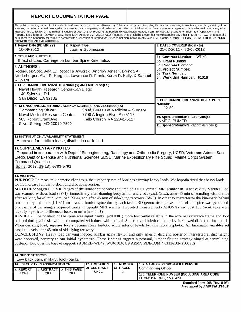
13. SUPPLEMENTARY NOTES Prepared in cooperation with Dept of Bioengineering, Radiology and Orthopedic Surgery, UCSD, Veterans Admin, San Diego, Dept of Exercise and Nutritional Sciences SDSU, Marine Expeditionary Rifle Squad, Marine Corps System Command Quantico. Spine, 2013, 38(13), e783-e791 14. ABSTRACT PURPOSE: To measure kinematic changes in the lumbar spines of Marines carrying heavy loads. We hypothesized that heavy loads would increase lumbar lordosis and disc compression. METHODS: Sagittal T2 MR images of the lumbar spine were acquired on a 0.6T vertical MRI scanner in 10 active duty Marines. Each was scanned without load (SW1), immediately after donning body armor and a backpack (SL2), after 45 min of standing with the loa after walking for 45 min with load (SL4), and after 45 min of side-lying recovery (SW5). In order to characterize the kinematic behavio functional spinal units (L1-S1) and overall lumbar spine during each task a 3D geometric representation of the spine was generated processing of the images acquired using an upright MRI scanner. Repeated measurements ANOVAs and post hoc Sidak tests were identify significant differences between tasks (α = 0.05). RESULTS: The position of the spine was significantly (p<0.0001) more horizontal relative to the external reference frame and lordo reduced during all tasks with load compared with those without load. Superior and inferior lumbar levels showed different kinematic be When carrying load, superior levels became more lordotic while inferior levels became more kyphotic. All kinematic variables retu baseline levels after 45 min of side-lying recovery. CONCLUSIONS: Heavy load carrying induced lumbar spine flexion and only anterior disc and posterior intervertebral disc height were observed, contrary to our initial hypothesis. These findings suggest a postural, lumbar flexion strategy aimed at centralizing posterior load over the base of support. (BUMED-WII42, WU61016, US ARMY RDECOM N6311610MP00182)
14. SUBJECT TERMS Low back pain, military, back-packs 16. SECURITY CLASSIFICATION OF: 17. LIMITATION
OF ABSTRACT UNCL
18. NUMBER OF PAGES 9
18a. NAME OF RESPONSIBLE PERSON Commanding Officer a. REPORT
UNCL b.ABSTRACT
UNCL b. THIS PAGE
UNCL 18b. TELEPHONE NUMBER (INCLUDING AREA CODE) COMM/DSN: (619) 553-8429
Standard Form 298 (Rev. 8-98) Prescribed by ANSI Std. Z39-18

![KINEMATICS - new.excellencia.co.innew.excellencia.co.in/college/web/pdf/Kinematics-merged.pdf · KINEMATICS KINEMATICS WORKSHEET 1 1) Displacement is a _____ [ ] 1) Vector quantity](https://img.pdfslide.us/doc/110x75/5f356d4687229051801abace/kinematics-new-kinematics-kinematics-worksheet-1-1-displacement-is-a-.jpg)