Embed Size (px)
Citation preview
EFFECT OF LAY ANGLE OF ANTI-BUCKLING TAPE ON LATERAL BUCKLING BEHAVIOR OF TENSILE ARMORS
Chongyao Zhou MARINTEK
7450 Trondheim, Norway
Svein Sævik NTNU
7491 Trondheim, Norway
Naiquan Ye MARINTEK
7450 Trondheim, Norway
Guomin Ji MARINTEK
7450 Trondheim, Norway
ABSTRACT During deep water flexible pipe installation, the pipe is
normally free hanging in empty condition from the installation
vessel to the seabed. This will introduce large hydrostatic
forces to the pipe causing true wall compression. In addition,
the pipe will be exposed to cyclic bending caused by waves
and vessel motion. The combination of true wall axial
compression and cyclic bending may lead to tensile armor
instability in both lateral and radial directions. If the anti-
buckling tape is assumed to be strong enough, the inner tensile
armor will lose its lateral stability first due to the gap that may
occur between the inner tensile armor and the pipe core, hence
restricting the available friction restraint forces. These may
further be reduced by cyclic motions that act to create slip
between the layers, hence introducing lateral buckling of the
tensile armor, with associated severe global torsion
deformation of the pipe, ultimately causing the pipe to lose its
integrity.
The anti-buckling tape is designed to prevent the radial
buckling behavior, however, its effect on lateral buckling has
not yet been documented in available literature. In the present
paper, the effect of the winding direction of the anti-buckling
tape on the twist of the cross section is studied, including
comparisons with available test data from literature.
1 INTRODUCTION The tensile armor is a key functional component of flexible
pipes providing resistance to gravity load and cyclic bending
caused by environmental loads. It normally consists of an even
number of layers which are cross wounded by a number of flat
rectangular wires with a lay angle of 30 to 55 degrees. For
deep water applications, the coupled effect from cyclic
bending and external pressure may lead to lateral and radial
buckling of tensile armors during pipe installation and
operation.
Any failure of the tensile armor wires may cause lose of
the pipe integrity and is therefore not permitted by design
standards. Ultimate and fatigue strength have been extensively
studied in recent years, while quite little effort has been
devoted to address the mechanism of the lateral and radial
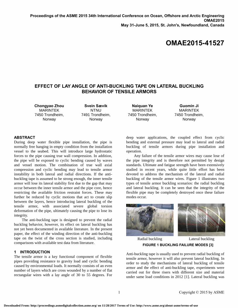
buckling of the tensile armor wires. Figure 1 illustrates two
types of tensile armor buckling scenarios: the radial buckling
and lateral buckling. It can be seen that the integrity of the
flexible pipe may be completely destroyed once these failure
modes occur.
Radial buckling Lateral buckling
FIGURE 1 BUCKLING FAILURE MODES [3]
Anti-buckling tape is usually used to prevent radial buckling of
tensile armor, however it will also prevent lateral buckling. In
order to study the mechanisms of lateral buckling of tensile
armor and the effect of anti-buckling tape, experiments were
carried out for three risers with different size and material
under same load conditions in 2012 [1]. Lateral buckling was
Proceedings of the ASME 2015 34th International Conference on Ocean, Offshore and Arctic Engineering OMAE2015
May 31-June 5, 2015, St. John's, Newfoundland, Canada
1 Copyright © 2015 by ASME
OMAE2015-41527
Downloaded From: http://proceedings.asmedigitalcollection.asme.org/ on 11/28/2017 Terms of Use: http://www.asme.org/about-asme/terms-of-use
first introduced and described by Braga and Kaleff [2] based
on experimental results. Further experiments to study the
lateral buckling behavior were carried out by Secher, Bectare
and Felix-Henry, studying flexible pipe behavior at 3000m
water depth [3], however, details were not available in
literature.
Lateral buckling behavior due to the cyclic bending was
studied by Østergaard, Lyckegaard and Andreasen [4]. The
work included both experimental tests and formulation of a
theoretical model under the assumption of no friction [5]-[6].
In the present work, the effect of friction is included and
the focus is on the effect of anti-buckling tape with respect to
the lateral failure mode.
2 THEORETICAL BACKGROUND
2.1 Theoretical model The axial stress represents the primary component in the
tensile armor, providing structural strength in the axial
direction (tension and end cap). The primary stresses are
mainly caused by axisymmetric loads, including tension,
torsion, internal and external pressure loads. In addition
secondary stresses will occur due to local bending and friction
due to bending. Curved beam theory can be used for the tensile armor
wire which is a long and thin slender structure. The theoretical
model applied here has already been presented elsewhere by
the Sævik, Thorsen and Li, [7], [9], including tensile armor
and core contact elements (HSHEAR353 and HCONT353).
However, since then a few more elements have been
developed. These are:
The HSHEAR363 element that enables to model the
tape, pressure spiral and sheath layers
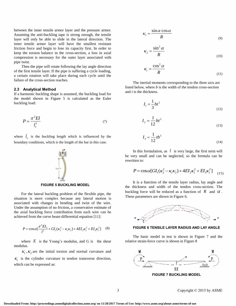
The HCONT363 element that enables to model
contact between the tensile armor and the tape,
sheath and pressure spiral layers.
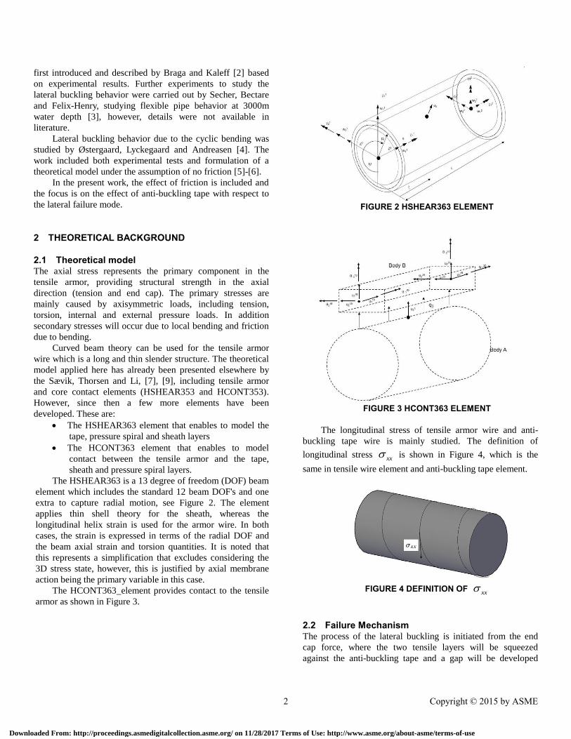
The HSHEAR363 is a 13 degree of freedom (DOF) beam
element which includes the standard 12 beam DOF's and one
extra to capture radial motion, see Figure 2. The element
applies thin shell theory for the sheath, whereas the
longitudinal helix strain is used for the armor wire. In both
cases, the strain is expressed in terms of the radial DOF and
the beam axial strain and torsion quantities. It is noted that
this represents a simplification that excludes considering the
3D stress state, however, this is justified by axial membrane
action being the primary variable in this case.
The HCONT363_element provides contact to the tensile
armor as shown in Figure 3.
FIGURE 2 HSHEAR363 ELEMENT
FIGURE 3 HCONT363 ELEMENT
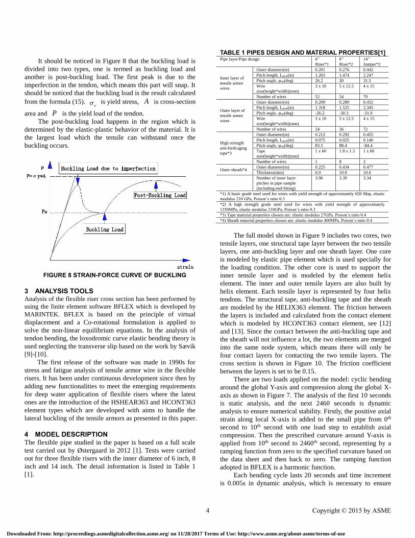
The longitudinal stress of tensile armor wire and anti-
buckling tape wire is mainly studied. The definition of
longitudinal stress xx
is shown in Figure 4, which is the
same in tensile wire element and anti-buckling tape element.
FIGURE 4 DEFINITION OF xx
2.2 Failure Mechanism The process of the lateral buckling is initiated from the end
cap force, where the two tensile layers will be squeezed
against the anti-buckling tape and a gap will be developed
2 Copyright © 2015 by ASME
Downloaded From: http://proceedings.asmedigitalcollection.asme.org/ on 11/28/2017 Terms of Use: http://www.asme.org/about-asme/terms-of-use
between the inner tensile armor layer and the pressure armor.
Assuming the anti-buckling tape is strong enough, the tensile
layer will only be able to slide in the lateral direction. The
inner tensile armor layer will have the smallest resistant
friction force and begin to lose its capacity first. In order to
keep the torsion balance in the cross-section, a loss in axial
compression is necessary for the outer layer associated with
pipe twist.
Then the pipe will rotate following the lay angle direction
of the first tensile layer. If the pipe is suffering a cycle loading,
a certain rotation will take place during each cycle until the
failure of the cross-section reaches.
2.3 Analytical Method If a harmonic buckling shape is assumed, the buckling load for
the model shown in Figure 5 is calculated as the Euler
buckling load:
2
2
e
EIP
l
(7)
where el is the buckling length which is influenced by the
boundary conditions, which is the length of the bar in this case.
FIGURE 5 BUCKLING MODEL
For the lateral buckling problem of the flexible pipe, the
situation is more complex because any lateral motion is
associated with changes in bending and twist of the wire.
Under the assumption of no friction, a conservative estimate of
the axial buckling force contribution from each wire can be
achieved from the curve beam differential equation [11]:
2
2 2 231 2 2 2 1 3 12
cos [ ( ) 4 ]t
EIP GI EI EI
l
(8)
where E is the Young’s modulus, and G is the shear
modulus.
1 , 2 are the initial torsion and normal curvature and
t is the cylinder curvature in tendon transverse direction,
which can be expressed as:
1
sin cos
R
(9)
2
2
sin
R
(10)
2cost
R
(11)
The inertial moments corresponding to the three axis are
listed below, where b is the width of the tendon cross-section
and t is the thickness.
3
1
1
3I bt
(12)
3
2
1
12I bt
(13)
3
3
1
12I tb
(14)
In this formulation, as l is very large, the first term will
be very small and can be neglected, so the formula can be
rewritten to:
2 2 2
1 2 2 2 1 3 1cos [ ( ) 4 ]tP GI EI EI (15)
It is a function of the tensile layer radius, lay angle and
the thickness and width of the tendon cross-section. The
buckling force will be reduced as a function of R and .
These parameters are shown in Figure 6.
FIGURE 6 TENSILE LAYER RADIUS AND LAY ANGLE
The basic model in test is shown in Figure 7 and the
relative strain-force curve is shown in Figure 8
FIGURE 7 BUCKLING MODEL
3 Copyright © 2015 by ASME
Downloaded From: http://proceedings.asmedigitalcollection.asme.org/ on 11/28/2017 Terms of Use: http://www.asme.org/about-asme/terms-of-use
It should be noticed in Figure 8 that the buckling load is
divided into two types, one is termed as buckling load and
another is post-buckling load. The first peak is due to the
imperfection in the tendon, which means this part will snap. It
should be noticed that the buckling load is the result calculated
from the formula (15). y is yield stress, A is cross-section
area and P is the yield load of the tendon.
The post-buckling load happens in the region which is
determined by the elastic-plastic behavior of the material. It is
the largest load which the tensile can withstand once the
buckling occurs.
FIGURE 8 STRAIN-FORCE CURVE OF BUCKLING
3 ANALYSIS TOOLS Analysis of the flexible riser cross section has been performed by
using the finite element software BFLEX which is developed by
MARINTEK. BFLEX is based on the principle of virtual
displacement and a Co-rotational formulation is applied to
solve the non-linear equilibrium equations. In the analysis of
tendon bending, the loxodromic curve elastic bending theory is
used neglecting the transverse slip based on the work by Sævik
[9]-[10].
The first release of the software was made in 1990s for
stress and fatigue analysis of tensile armor wire in the flexible
risers. It has been under continuous development since then by
adding new functionalities to meet the emerging requirements
for deep water application of flexible risers where the latest
ones are the introduction of the HSHEAR363 and HCONT363
element types which are developed with aims to handle the
lateral buckling of the tensile armors as presented in this paper.
4 MODEL DESCRIPTION The flexible pipe studied in the paper is based on a full scale
test carried out by Østergaard in 2012 [1]. Tests were carried
out for three flexible risers with the inner diameter of 6 inch, 8
inch and 14 inch. The detail information is listed in Table 1
[1].
TABLE 1 PIPES DESIGN AND MATERIAL PROPERTIES[1] Pipe layer/Pipe design 6”
Riser*1
8”
Riser*2
14”
Jumper*2
Inner layer of
tensile armor
wires
Outer diameter(m) 0.201 0.276 0.442
Pitch length, Lpitch(m) 1.263 1.474 2.247
Pitch angle, φhel(deg) 26.2 30 31.5
Wire
size(height*width)(mm)
3 x 10 5 x 12.5 4 x 15
Number of wires 52 54 70
Outer layer of
tensile armor
wires
Outer diameter(m) 0.209 0.289 0.452
Pitch length, Lpitch(m) 1.318 1.525 2.345
Pitch angle, φhel(deg) -26.2 -30.3 -31.0
Wire
size(height*width)(mm)
3 x 10 5 x 12.5 4 x 15
Number of wires 54 56 72
High strength
anti-birdcaging
tape*3
Outer diameter(m) 0.212 0.292 0.455
Pitch length, Lpitch(m) 0.075 0.025 0.140
Pitch angle, φhel(deg) 83.5 88.4 -84.4
Tape
size(height*width)(mm)
1 x 60 1.8 x 1.3 1 x 60
Number of wires 1 8 2
Outer sheath*4 Outer diameter(m) 0.225 0.434 0.477
Thickness(mm) 6.0 10.0 10.0
Number of inner layer
pitches in pipe sample
(including end-fitting)
3.96 3.39 3.34
*1) A basic grade steel used for wires with yield strength of approximately 650 Map, elastic
modulus 210 GPa, Poison’s ratio 0.3
*2) A high strength grade steel used for wires with yield strength of approximately
1350MPa, elastic modulus 210GPa, Poison’s ratio 0.3
*3) Tape material properties chosen are: elastic modulus 27GPa. Poison’s ratio 0.4
*4) Sheath material properties chosen are: elastic modulus 400MPa, Poison’s ratio 0.4
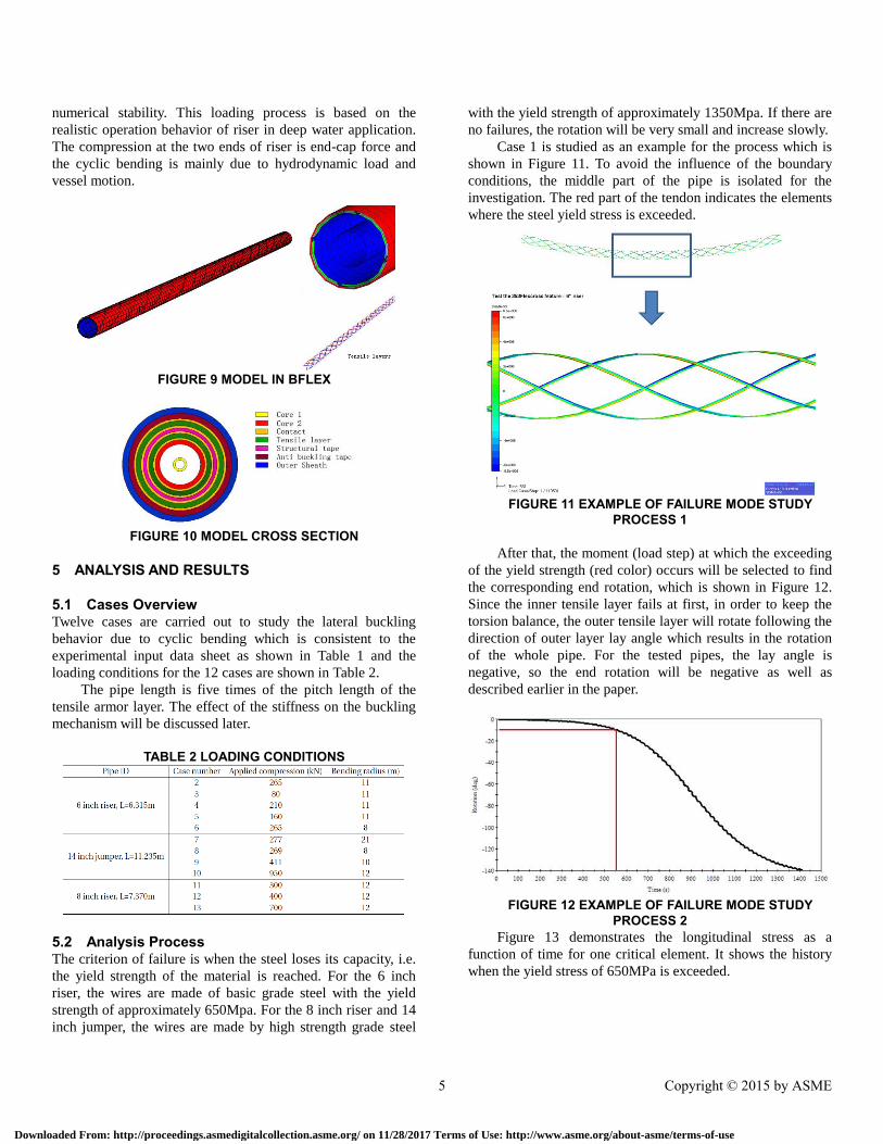
The full model shown in Figure 9 includes two cores, two
tensile layers, one structural tape layer between the two tensile
layers, one anti-buckling layer and one sheath layer. One core
is modeled by elastic pipe element which is used specially for
the loading condition. The other core is used to support the
inner tensile layer and is modeled by the element helix
element. The inner and outer tensile layers are also built by
helix element. Each tensile layer is represented by four helix
tendons. The structural tape, anti-buckling tape and the sheath
are modeled by the HELIX363 element. The friction between
the layers is included and calculated from the contact element
which is modeled by HCONT363 contact element, see [12]
and [13]. Since the contact between the anti-buckling tape and
the sheath will not influence a lot, the two elements are merged
into the same node system, which means there will only be
four contact layers for contacting the two tensile layers. The
cross section is shown in Figure 10. The friction coefficient
between the layers is set to be 0.15.
There are two loads applied on the model: cyclic bending
around the global Y-axis and compression along the global X-
axis as shown in Figure 7. The analysis of the first 10 seconds
is static analysis, and the next 2460 seconds is dynamic
analysis to ensure numerical stability. Firstly, the positive axial
strain along local X-axis is added to the small pipe from 0th
second to 10th second with one load step to establish axial
compression. Then the prescribed curvature around Y-axis is
applied from 10th second to 2460th second, representing by a
ramping function from zero to the specified curvature based on
the data sheet and then back to zero. The ramping function
adopted in BFLEX is a harmonic function.
Each bending cycle lasts 20 seconds and time increment
is 0.005s in dynamic analysis, which is necessary to ensure
4 Copyright © 2015 by ASME
Downloaded From: http://proceedings.asmedigitalcollection.asme.org/ on 11/28/2017 Terms of Use: http://www.asme.org/about-asme/terms-of-use
numerical stability. This loading process is based on the
realistic operation behavior of riser in deep water application.
The compression at the two ends of riser is end-cap force and
the cyclic bending is mainly due to hydrodynamic load and
vessel motion.
FIGURE 9 MODEL IN BFLEX
FIGURE 10 MODEL CROSS SECTION
5 ANALYSIS AND RESULTS
5.1 Cases Overview Twelve cases are carried out to study the lateral buckling
behavior due to cyclic bending which is consistent to the
experimental input data sheet as shown in Table 1 and the
loading conditions for the 12 cases are shown in Table 2.
The pipe length is five times of the pitch length of the
tensile armor layer. The effect of the stiffness on the buckling
mechanism will be discussed later.
TABLE 2 LOADING CONDITIONS
5.2 Analysis Process The criterion of failure is when the steel loses its capacity, i.e.
the yield strength of the material is reached. For the 6 inch
riser, the wires are made of basic grade steel with the yield
strength of approximately 650Mpa. For the 8 inch riser and 14
inch jumper, the wires are made by high strength grade steel
with the yield strength of approximately 1350Mpa. If there are
no failures, the rotation will be very small and increase slowly.
Case 1 is studied as an example for the process which is
shown in Figure 11. To avoid the influence of the boundary
conditions, the middle part of the pipe is isolated for the
investigation. The red part of the tendon indicates the elements
where the steel yield stress is exceeded.
FIGURE 11 EXAMPLE OF FAILURE MODE STUDY
PROCESS 1
After that, the moment (load step) at which the exceeding
of the yield strength (red color) occurs will be selected to find
the corresponding end rotation, which is shown in Figure 12.
Since the inner tensile layer fails at first, in order to keep the
torsion balance, the outer tensile layer will rotate following the
direction of outer layer lay angle which results in the rotation
of the whole pipe. For the tested pipes, the lay angle is
negative, so the end rotation will be negative as well as
described earlier in the paper.
FIGURE 12 EXAMPLE OF FAILURE MODE STUDY
PROCESS 2 Figure 13 demonstrates the longitudinal stress as a
function of time for one critical element. It shows the history
when the yield stress of 650MPa is exceeded.
5 Copyright © 2015 by ASME
Downloaded From: http://proceedings.asmedigitalcollection.asme.org/ on 11/28/2017 Terms of Use: http://www.asme.org/about-asme/terms-of-use
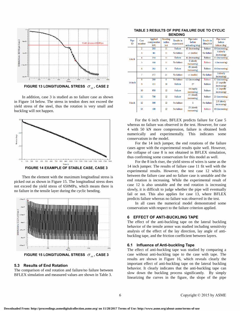
FIGURE 13 LONGITUDINAL STRESS xx , CASE 2
In addition, case 3 is studied as no failure case as shown
in Figure 14 below. The stress in tendon does not exceed the
yield stress of the steel, thus the rotation is very small and
buckling will not happen.
FIGURE 14 EXAMPLE OF STABLE CASE, CASE 3
Then the element with the maximum longitudinal stress is
picked out as shown in Figure 15. The longitudinal stress does
not exceed the yield stress of 650MPa, which means there is
no failure in the tensile layer during the cyclic bending.
FIGURE 15 LONGITUDINAL STRESS xx , CASE 3
5.3 Results of End Rotation The comparison of end rotation and failure/no failure between
BFLEX simulation and measured values are shown in Table 3.
TABLE 3 RESULTS OF PIPE FAILURE DUE TO CYCLIC BENDING
For the 6 inch riser, BFLEX predicts failure for Case 5
whereas no failure was observed in the test. However, for case
4 with 50 kN more compression, failure is obtained both
numerically and experimentally. This indicates some
conservatism in the model.
For the 14 inch jumper, the end rotations of the failure
cases agree with the experimental results quite well. However,
the collapse of case 8 is not obtained in BFLEX simulation,
thus confirming some conservatism for this model as well.
For the 8 inch riser, the yield stress of wires is same as the
14 inch jumper. The results of failure case 11 fit well with the
experimental results. However, the test case 12 which is
between the failure case and no failure case is unstable and the
end rotation is increasing. While the experimental result of
case 12 is also unstable and the end rotation is increasing
slowly, it is difficult to judge whether the pipe will eventually
fail or not. This also applies for case 13, where BFLEX
predicts failure whereas no failure was observed in the test.
In all cases the numerical model demonstrated some
conservatism with respect to the failure criterion applied.
6 EFFECT OF ANTI-BUCKLING TAPE The effect of the anti-buckling tape on the lateral buckling
behavior of the tensile armor was studied including sensitivity
analysis of the effect of the lay direction, lay angle of anti-
buckling tape, and the friction coefficient between layers.
6.1 Influence of Anti-buckling Tape The effect of anti-buckling tape was studied by comparing a
case without anti-buckling tape to the case with tape. The
results are shown in Figure 16, which reveals clearly the
important effect of anti-buckling tape on the lateral buckling
behavior. It clearly indicates that the anti-buckling tape can
slow down the buckling process significantly. By simply
linearizing the curves in the figure, the slope of the pipe
6 Copyright © 2015 by ASME
Downloaded From: http://proceedings.asmedigitalcollection.asme.org/ on 11/28/2017 Terms of Use: http://www.asme.org/about-asme/terms-of-use
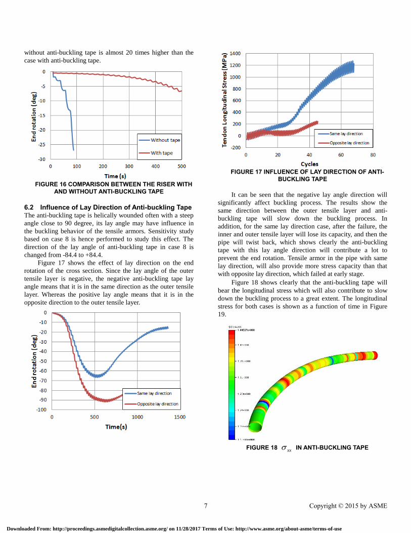
without anti-buckling tape is almost 20 times higher than the
case with anti-buckling tape.
FIGURE 16 COMPARISON BETWEEN THE RISER WITH
AND WITHOUT ANTI-BUCKLING TAPE
6.2 Influence of Lay Direction of Anti-buckling Tape The anti-buckling tape is helically wounded often with a steep
angle close to 90 degree, its lay angle may have influence in
the buckling behavior of the tensile armors. Sensitivity study
based on case 8 is hence performed to study this effect. The
direction of the lay angle of anti-buckling tape in case 8 is
changed from -84.4 to +84.4.
Figure 17 shows the effect of lay direction on the end
rotation of the cross section. Since the lay angle of the outer
tensile layer is negative, the negative anti-buckling tape lay
angle means that it is in the same direction as the outer tensile
layer. Whereas the positive lay angle means that it is in the
opposite direction to the outer tensile layer.
FIGURE 17 INFLUENCE OF LAY DIRECTION OF ANTI-
BUCKLING TAPE
It can be seen that the negative lay angle direction will
significantly affect buckling process. The results show the
same direction between the outer tensile layer and anti-
buckling tape will slow down the buckling process. In
addition, for the same lay direction case, after the failure, the
inner and outer tensile layer will lose its capacity, and then the
pipe will twist back, which shows clearly the anti-buckling
tape with this lay angle direction will contribute a lot to
prevent the end rotation. Tensile armor in the pipe with same
lay direction, will also provide more stress capacity than that
with opposite lay direction, which failed at early stage.
Figure 18 shows clearly that the anti-buckling tape will
bear the longitudinal stress which will also contribute to slow
down the buckling process to a great extent. The longitudinal
stress for both cases is shown as a function of time in Figure
19.
FIGURE 18 xx IN ANTI-BUCKLING TAPE
7 Copyright © 2015 by ASME
Downloaded From: http://proceedings.asmedigitalcollection.asme.org/ on 11/28/2017 Terms of Use: http://www.asme.org/about-asme/terms-of-use
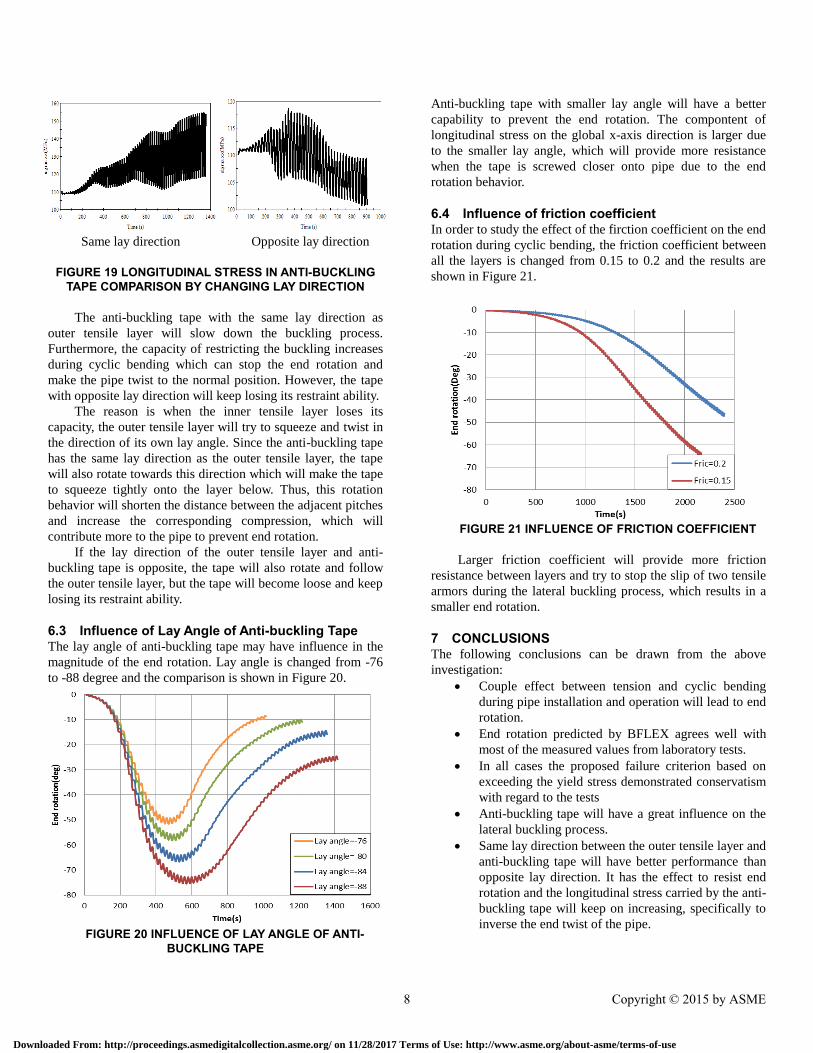
Same lay direction Opposite lay direction
FIGURE 19 LONGITUDINAL STRESS IN ANTI-BUCKLING TAPE COMPARISON BY CHANGING LAY DIRECTION
The anti-buckling tape with the same lay direction as
outer tensile layer will slow down the buckling process.
Furthermore, the capacity of restricting the buckling increases
during cyclic bending which can stop the end rotation and
make the pipe twist to the normal position. However, the tape
with opposite lay direction will keep losing its restraint ability.
The reason is when the inner tensile layer loses its
capacity, the outer tensile layer will try to squeeze and twist in
the direction of its own lay angle. Since the anti-buckling tape
has the same lay direction as the outer tensile layer, the tape
will also rotate towards this direction which will make the tape
to squeeze tightly onto the layer below. Thus, this rotation
behavior will shorten the distance between the adjacent pitches
and increase the corresponding compression, which will
contribute more to the pipe to prevent end rotation.
If the lay direction of the outer tensile layer and anti-
buckling tape is opposite, the tape will also rotate and follow
the outer tensile layer, but the tape will become loose and keep
losing its restraint ability.
6.3 Influence of Lay Angle of Anti-buckling Tape The lay angle of anti-buckling tape may have influence in the
magnitude of the end rotation. Lay angle is changed from -76
to -88 degree and the comparison is shown in Figure 20.
FIGURE 20 INFLUENCE OF LAY ANGLE OF ANTI-
BUCKLING TAPE
Anti-buckling tape with smaller lay angle will have a better
capability to prevent the end rotation. The compontent of
longitudinal stress on the global x-axis direction is larger due
to the smaller lay angle, which will provide more resistance
when the tape is screwed closer onto pipe due to the end
rotation behavior.
6.4 Influence of friction coefficient In order to study the effect of the firction coefficient on the end
rotation during cyclic bending, the friction coefficient between
all the layers is changed from 0.15 to 0.2 and the results are
shown in Figure 21.
FIGURE 21 INFLUENCE OF FRICTION COEFFICIENT
Larger friction coefficient will provide more friction
resistance between layers and try to stop the slip of two tensile
armors during the lateral buckling process, which results in a
smaller end rotation.
7 CONCLUSIONS The following conclusions can be drawn from the above
investigation:
Couple effect between tension and cyclic bending
during pipe installation and operation will lead to end
rotation.
End rotation predicted by BFLEX agrees well with
most of the measured values from laboratory tests.
In all cases the proposed failure criterion based on
exceeding the yield stress demonstrated conservatism
with regard to the tests
Anti-buckling tape will have a great influence on the
lateral buckling process.
Same lay direction between the outer tensile layer and
anti-buckling tape will have better performance than
opposite lay direction. It has the effect to resist end
rotation and the longitudinal stress carried by the anti-
buckling tape will keep on increasing, specifically to
inverse the end twist of the pipe.
8 Copyright © 2015 by ASME
Downloaded From: http://proceedings.asmedigitalcollection.asme.org/ on 11/28/2017 Terms of Use: http://www.asme.org/about-asme/terms-of-use
Smaller lay angle will have better performance than
higher lay angle.
Larger friction coefficient between layers will result
in smaller end rotation.
It is important to notice that the end rotation phenomenon
studied here is based on the assumption that the anti-buckling
tape is strong enough and tensile layer has only one way to go
which will result in lateral buckling. The radial buckling is
assumed not to occur. However, the fact is that if both buckling
modes are considered, the design of anti-buckling tape should
also take both of modes into account. Smaller lay angle of anti-
buckling tape will provide more resistance to lateral buckling,
however, the radial buckling capacity will be reduced. So it is
necessary to consider all these effects for an optimized design.
NOMENCLATURE n number of tensile armor wires
Lp pitch length of the tensile armor wire
le buckling length
l pipe length
ɛ gap between adjacent tensile armor wires
b width of tensile armor wire
α lay angle of the tensile armor wire
R mean radius of the tensile armor layer
Ψ angular coordinate starting from the lower side
of the pipe
Ii moment inertia respect to three axial
β2 the global curvature at the cross-section center
β2c the critical global curvature with maximum
shear force in the tensile wire
ωip dynamic bending, torsion and curvature
component of the wire for i=1,2,3 respectively
κ1 initial torsion
κ2 normal curvature
κ3 transverse curvature
κt cylinder curvature in tendon transverse direction
σxx longitudinal stress in wire
u1 longitudinal relative displacement
u1p longitudinal relative displacement by plane
remain plane assumption
P buckling load
b width of the tendon
t thickness of the tape layer
G shear modulus
E Young's modulus of the material
REFERENCES [1] Niels Højen Østergaard. On lateral buckling of
armoring wires in flexible pipes. PhD thesis,
Aalborg University/NKT-Flexibles, Aalborg East,
Denmark, 2012.
[2] M.P. Braga and P Kaleff. Flexible pipe sensitivity
to bird-caging and armor wire lateral buckling.
Proceedings of OMAE, 2004.
[3] P. Secher, F. Bectarte, and A. Felix-Henry. Lateral
buckling of armor wires in flexible pipes:
researching 3000m water depth. Proceedings of
OMAE, 2011.
[4] N.H. Østergaard, A. Lyckegaard, and J. Andreasen.
Simplified approaches to modeling of lateral wire
buckling in the tensile armor of flexible pipes.
Proceedings of OMAE, 2012.
[5] N.H. Østergaard, A. Lyckegaard, and J. Andreasen.
On lateral buckling failure of armor wires in
flexible pipes. Proceedings of OMAE, 2011.
[6] N.H. Østergaard, A. Lyckegaard, and J. Andreasen.
A method for prediction of the equilibrium state of
a long and slender wire on a frictionless toroid
applied for analysis of flexible pipe structures.
Engineering Structures, Vol. 34, pp. 391-399,2012.
[7] Sævik, S., Theoretical and experimental studies of
stresses in flexible pipes, Computers and Structures
89(2011), pp. 2273-2291.
[8] Chongyao, Zhou; Sævik, S; Naiquan Ye. Effect of
anti-wear tape on behavior of flexible risers
[9] Sævik, S., Thorsen, M.J.: Techniques for
predicting tensile armor buckling and fatigue in
deep water flexible pipes, Proceedings of the 31th
International Conference on Ocean, Offshore and
Arctic Engineering, Brazil.
[10] Sævik, S., Li, H., Shear interaction and transverse
buckling of tensile armors in flexible pipes,
Proceeding of the 32th International Conference on
Ocean, Offshore and Arctic Engineering, 2013,
Nantes, France.
[11] Sævik. S. and Guomin Ji. Differential equation for
evaluation transverse buckling behavior of tensile
armor wires. Proceedings of OMAE, 2014.
[12] Sævik. S. BFLEX2010 – Theory Manual.
MARINTEK, Trondheim, Norway, 2010
[13] Sævik. S. PhD Thesis, On Stresses and Fatigue in
Flexible Pipes, NTH, 1992.
9 Copyright © 2015 by ASME
Downloaded From: http://proceedings.asmedigitalcollection.asme.org/ on 11/28/2017 Terms of Use: http://www.asme.org/about-asme/terms-of-use