Embed Size (px)
Citation preview
NASA Technical Memorandum 87165
Effect of Interference Fits on Roller Bearing Fatigue Life
~
,NASA-TM-87165) EFFECT CN I N ' I E R E E R E N C B PITS N86- 196 16 ibl ROLLER B E A R I N G PAllGUE LIFE ( N A S A ) 24 y
Z A02/flP B O 1 CSCL 1 3 1 Unc las
G3/37 05177
Harold H. Coe and h v i s Research center CkveW,Ohio
c
- 9
January 1986 I_
https://ntrs.nasa.gov/search.jsp?R=19860010145 2018-05-28T03:27:39+00:00Z
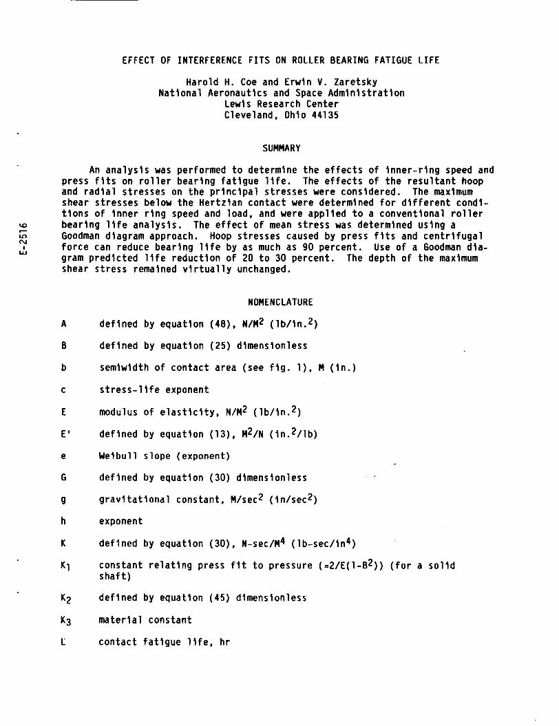
EFFECT OF INTERFERENCE F I T S ON ROLLER BEARING FATIGUE LIFE
Harold H. Coe and Erwin V. Zaretsky Nat iona l Aeronautics and Space Admin is t ra t ion
Lewis Research Center Cleveland, Ohio 44135
SUMMARY
An ana lys i s was performed t o determine the e f f e c t s o f i nne r - r i ng speed and press f i t s on r o l l e r bear ing f a t i g u e l i f e . The e f f e c t s o f t he r e s u l t a n t hoop and r a d i a l stresses on the p r i n c i p a l stresses were considered. The maximum shear stresses below the Her tz ian contact were determined f o r d i f f e r e n t condl- t i o n s o f i nne r r i n g speed and load, and were app l ied t o a convent ional r o l l e r bear ing l i f e ana lys is . Goodman diagram approach. Hoop stresses caused by press f i t s and c e n t r i f u g a l f o r c e can reduce bear ing l i f e by as much as 90 percent. Use o f a Goodman d ia - gram p red ic ted l i f e reduc t ion o f 20 t o 30 percent. The depth o f t he maximum shear s t ress remained v l r t u a l l y unchanged.
The e f f e c t o f mean s t ress was determined us ing a
A
B
b
C
E
E '
e
G
9
h
K
K1
K2
K3
c
NOMENCLATURE
def ined by equat ion (sa) , N/M2 ( l b / i n .2 )
de f ined by equat ion (25 ) dimensionless
semiwidth o f contact area (see f i g . l), M ( i n . )
s t r e s s - l i f e exponent
modulus o f e l a s t i c i t y , N/M2 ( l b / i n .2 )
de f ined by equat ion (13), M2/N ( i n .2 / l b )
Weibul l s lope (exponent)
def ined by equat ion (30) dimensionless
g r a v i t a t i o n a l constant, M/sec2 ( in /sec2)
exponent
de f ined by equat ion (30), N-sec/M4 ( lb-sec/ in4)
constant r e l a t i n g press f i t t o pressure (=2/E(1-B2)) ( f o r a s o l i d s h a f t )
de f ined by equat ion (45) dimensionless
m a t e r i a l constant
con tac t f a t i g u e l i f e , h r
LR
a
m
p i
PO 9
p;
R
R '
R r
r
Y
Y Y
Y
Ymax
2
l i f e r a t i o , def ined by equat ion (52)
l eng th o f contact area ( f i g . l), M ( i n . )
def ined by equat ion (48), N/M2 ( l b / i n . 2 )
pressure on
pressure on ro, N/M2 ( lb / in .2)
r o l l e r load, N ( l b )
rad ius o f curvature, M ( i n . )
r a t i o , def ined by equat ion ( 4 4 ) dimensionless
rad ius o f r o l l e r ( f i g . 3), M ( i n . )
rad ius t o element ( f i g . 3), M ( I n . )
r i n g i nne r rad ius ( f i g . 3), M ( i n . )
r i n g ou te r rad ius ( f i g . 3) , M ( i n . )
Her tz s t ress a t center o f contact , N/M2 ( l b / i n . 2 )
u l t i m a t e s t reng th o f ma te r ia l , N/mZ ( l b / i n .2 )
p r i n c i p a l s t ress i n t h e
p r i n c i p a l s t ress i n the
r i , due t o press f i t , N/M2 ( l b A n . 2 )
Y-d i rect ion (eq. (34)) , N/M2 ( l b / i n . 2 )
2 -d i rec t i on (eq. (33)), N/M2 ( l b / i n .2 )
s i m p l i f y i n g term ( = V I t u2)
dimensionless depth below surface (=Z/b)
stressed volume, M3 ( i n .3 )
a x i s perpendicular t o r o l l i n g d i r e c t i o n
p r i n c i p a l s t ress, X-direct ion, Her tz loading only (eq. ( 4 ) ) , N/M2 ( 1 b / i n .2)
a x i s i n d i r e c t i o n o f r o l l i n g
p r i n c i p a l s t ress, Y-direct ion, Her tz loading only (eq. ( 5 ) ) , N/M2 ( l b / i n . 2 )
def ined by eq. (25) dimensionless *
value o f y a t Tmax dimensionless
d is tance below Her tz contact surface ( f i g . l), M ( i n . ) o r a x i s i n d i r e c t i o n o f Her t z ian loading
2
zo
ZZ
Y
A
d
e
A
U
.*
ZP
a
T
Ta
l m
Tmax
0
value of depth t o maximum shear ing s t ress, M ( In . )
p r i n c i p a l s t ress, Z-d i rect ion, Her tz load ing on ly (eq. ( 6 ) ) . N/M2 ( l b / i n .2 )
dens i t y o f ma te r ia l , N/M3 ( l b / h 3 )
press f i t on rad ius, M ( i n . )
Poisson's r a t i o ( a l s o U ) dimensionless
de f ined by eq. ( l o ) , N/M2 ( i n . z / l b )
de f ined by eq. (15) , M3/N ( k 3 / l b )
Poisson's r a t i o ( a l s o 6 ) dimensionless
P i (=3.14159)
curva ture sum (=l/Ra t l /Rb), l/M ( l / i n . )
s t ress, N/M2 ( lb / in .2 )
maximurn shear s t ress , N/M2 ( l b / i n .2 )
amp1 i tude o f T , N/M2 ( 1 b / ln . 2,
e f f e c t i v e maxlmum shear s t ress,
mean value o f T, N/M2 ( l b / i n .2 )
maximum value o f T , N/M2 ( l b / i n .2 )
i nne r r i n g speed, rad/sec
N/M2 ( l b / i n .2 )
Subscr ip ts
a body a
b body b
CF
H
h hoop- o r Y-d i rec t ion
due t o i nne r r i n g speed
based on Her tz load ing on ly
. PF
T
r rad1 a1 - o r 2-di rec t i on
due t o press f i t on i nne r r i n g
based on press f i t and r i n g speed and Her tz load ing
3
INTRODUCTION
With advancements in turbomachinery, rolling-element bearing operating speeds and temperatures have been steadily increasing. loading on the bearing inner ring-shaft interface, and differential tempera- tures, the inner ring expands or grows relative to the shaft. This can result, even in a highly loaded bearing application, in the inner ring "walking" around the shaft. The most benign effect of this phenomenon is replacement of the bearing at overhaul and plating and regrinding of the shaft at the bearing position due to wear. However, in the most extreme cases, the wear of the shaft can either act as a stress raiser to cause fatigue or fracture of the shaft or in the case of hollow shafts actually wear through the shaft. In these cases, catastrophic or secondary damage can occur.
Because of centrifugal
In order to prevent motion of the inner ring around a shaft, designers have been specifying very tight interference fit between the inner ring and shaft where it is not practical to provide for a keyway or locknut arrangement. The interference fit is usually based upon the anticipated growth of the shaft and bearing under the most severe operating conditions. These conditions some- times only exist for short time periods in the machine's operating cycle. Nevertheless, it is a very important design consideration for both safety of operation as well as maintainability. In recent years it has been noticed by some engineers that bearings which have higher than usual interference or press fits may have field lives which are shorter than those which were anticipated or calculated. The failure mechanlsm j s usually classlcal rolling-element (subsurface) fatigue. There has been no public documentation of the phenomenon.
Residual compressive stresses near the surface of a rolling element increases the rolling-element fatigue life of the surface under rolling con- tact loading (refs. 1 to 4). These compressive residual stresses can be devel- oped for a number of processing operations such as grinding and shot peening (ref. 4). Tensile residual stresses while not common can negatively affect fatigue life. These tensile residual stresses would be analogous to those hoop tensile stresses which may be induced due to press fits and ring growth due to thermal and centrifugal effects. If residual stress can affect the fatigue life, then these other stresses which can be present may also alter the criti- cal subsurface shearing stress and affect rolling-element fatigue life of the bearing inner race.
Czyzewski (ref. 5 ) first postulated that tensile stresses in a cylindri- cal race imposed on a lubricated Hertzian contact would affect shearing stresses and, hence, rolling-element fatigue life. He performed an analysis and rolling-element fatigue tests of 45-mm bore roller bearing inner-races subjected to mechanically induced tensile stress. approximately 700 MN/m2 (102x103 psi). ninth ower stress-life relation.
ring fracture. rolling-element fatigue.
Maximum Hertzian stress was There is a suggestion of an inverse
At a hoop tensile stress of 80 MN/m2 (12x10 !ii psi) failure appears to be by a surface fatigue spa11 accompanied by
At the lower hoop stresses, the failure mode was by classical
The research reported herein was undertaken to investigate the effects of inner-ring press fits and centrifugal force on roller bearlng life. tives were (a) develop an equation to account for the effect of hoop stresses
The objec-
4
on maximum shearing stress of a Hertzian contact and (b) determine the magni- tude of the effects of press fit and centrifugal force on roller bearing life.
ANALYSIS
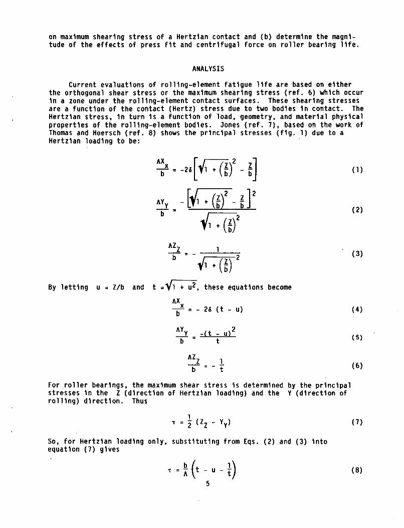
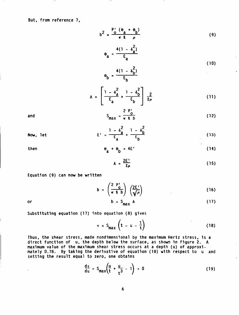
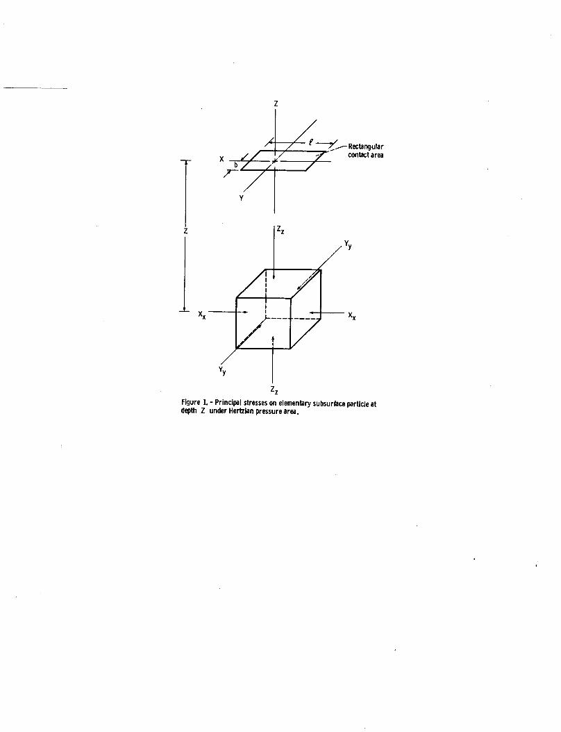
Current evaluations of rolling-element fatigue life are based on either the orthogonal shear stress or the maximum shearing stress (ref. 6) whlch occur in a zone under the rolling-element contact surfaces. These shearing stresses are a function of the contact (Hertz) stress due to two bodles in contact. The Hertzian stress, in turn is a function of load, geometry, and material physical properties of the rolling-element bodies. Jones (ref. 7), based on the work of Thomas and Hoersch (ref. 8) shows the principal stresses (fig. 1) due to a Hertzian loading to be:
1 L - = -
d*2 By letting u = Z/b and t = q s , these equations become
( 4 ) AXX - = - 26 (t - u) b
2 - - AyY -(t - u) b - t
1 t - = - - AZZ
b
( 3 )
For roller bearings, the maximum shear stress is determined b.y the principal stresses in the Z (direction of Hertzian loading) and the Y (direction of rolling) direction. Thus
1 T = 2 (ZZ - Yy)
So, for Hertzian loading only, substituting from Eqs. ( 2 ) and (3) into equation (7) gives
T = (t - u - $)
( 7 )
5
But, f rom reference 7,
P I ( e t eb)
r e P o a b2 = ( 9 )
and
Now, l e t
then
A =
2 P;, - -
'max - w a b
e t eb = 4 ~ ' a
Equation (9) can now be w r i t t e n
2 P '
b = (*) (F) A
= 'max o r
S u b s t i t u t i n g equat ion (17) i n t o equation (8 ) gives
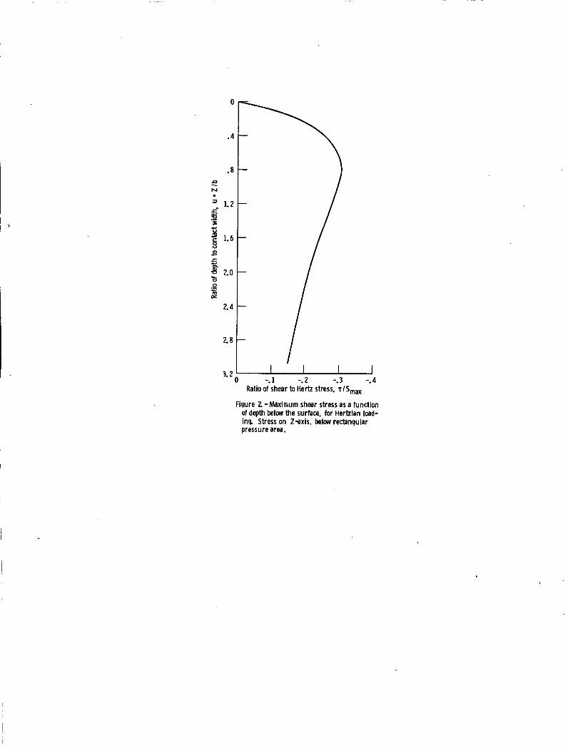
Thus, t h e shear s t ress, made nondimensional by t h e maximum Hertz s t ress, i s a d i r e c t f u n c t i o n o f u, t h e depth below t h e surface, as shown i n f i g u r e 2. A maximum value o f t h e maximum shear s t ress occurs a t a depth (u ) o f approxi- mately 0.78. By t a k i n g the d e r i v a t i v e o f equat ion (18) w i t h respect t o u and s e t t i n g the r e s u l t equal t o zero, one obta ins
- - d r
6
The s o l u t i o n t o equat ion (19) i s u = 0.78b152, and t h e corresponding equat ion f o r t he maximum shear s t ress becomes
Tmax = - 0.30028 Smax (20)
Equations (18) and (20) account f o r t he subsurface s t resses due on ly t o the Her tz lan contac t and do no t account f o r t he e f f e c t s o f press f i t t i n g an Inner r l n g on a s h a f t o r f o r t h e e f f e c t s o f I nne r - r l ng speed. These e f f e c t s can be accounted f o r , us ing the method o f superposi t ion, by determin ing the values o f subsurface s t ress I n the Z and Y d i r e c t i o n as a f u n c t i o n o f depth below the sur face t o correspond w i t h equations ( 5 ) and ( 6 ) .
Stress Due t o Press F i t
From reference 9 we can w r i t e , f o r t he hoop s t ress
Note t h a t Po = 0 and t h a t P i i s due t o a press f i t o f t he r i n g on a shaf t , t h a t i s ,
A pi = r, K~
Equation (21) can be w r i t t e n
2
PF = ro 2 - ri 2 [, t ($1 S i m i l a r l y , we can w r i t e , f o r t he r a d i a l s t r e s s
I f we l e t i r r - = I 3 and - = y r O r O
Equatlons (23) and (24) become
7
Pi B2 (ar) PF - - 1 - B 2 (1 -))
Stresses Due to Inner Ring Speed
From reference 9 we can write, for the hoop stress,
2
(ah) = 8(1 - - 2u v ) ($) 1: t r: t (F) - r2 (l I E:)] (28) CF
Similarly, for the radial stress
('r) = r o - r i - r - 8(1 - U ) 3 - 2 u CF
1 et
and using equation ( 2 5 ) , equations (28) and (29) become
(ah) = Kw2r2 0 CF
2 2 b - B 2 s-y2] - Y2
(ar) = KW ro CF
Combined Stresses
By the method of superposition, the principal stresses in the Z and Y directions become
and the maximum shear stress is
( 3 5 ) 1
1 = 5 ( S Z - SY)
To utilize these equations, however, one must determine the relation between u and y so that the stresses can all be determined at the same location.
8
o r
From geometry, ( f i g s . (1) and (3))
r = ro - Z = r - ub 0
and
S u b s t i t u t i n g equat ion (17) g ives
ub = l - - = y r - rO rO
r u =r(l 0 - y)
From f i g u r e ( 3 )
R + ro r - 1 1 + - -
ro Rr roRr Ep = -
S u b s t i t u t i n g equat ion (40) i n t o equat ion (15) gives
2E ' roRr
ro + Rr A =
Using equat lon (41) i n equat ion (39) l e t s us w r i t e
o r
where
For s i m p l i c i t y , l e t
then
R ' + 1 2SmaxE' (' - y, u =
r
Rr 0 R ' = -
R ' t 1 - K2 - 2SmaxE'
u = K2 (1 - y)
(36)
(37)
(43)
(44)
(45)
(46)
9
Proper substitution of equations (33) and (34) into equation (35) using equations ( 5 ) , ( 6 ) , (26), (27), (31), and (32) along with equation (17) leads to the following expression for the maximum shear stress as a function of depth below a Hertzian contact, accounting for both rlng press fit and ring speed.
where, for simplicity
Pi B2 2 m =
1 - 6
2 2 A = KU ro
Again, taking the derivative of equation (47) with respect to y and setting the result equal to zero leads to the value of y where the shear stress is a maximum. Using the chain rule that ds/dy - ds/du du/dy,
(49 ) - dr K [ a + $ - l ] + 2(m + + A(G - 1 ) y = 0 Y3 dY = - Smax 2
Using the Lundberg-Palmgren (ref. 10) analysis where
L =
1 /e
ma x
where from equation (49) and T~~ is its value from equation (47). the effect of the press fits and centrifugal force on inner race life can be determined. The effects of press fit would not, however, affect the life-of the outer race. However, centrifugal loading of the rollers on the outer race does affect the outer race life which can be readily determined. Knowing the life of the inner and outer raceways, the life of the bearing can be determined from Lundberg- Palmgren (ref. 10) as follows:
Zo is the depth to the maxllnum value of L e maximum shearing stress
1 + - 1 - - - - 1
Le L; L;
RESULTS AND DISCUSSION
Inner-Race Life
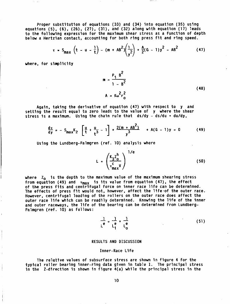
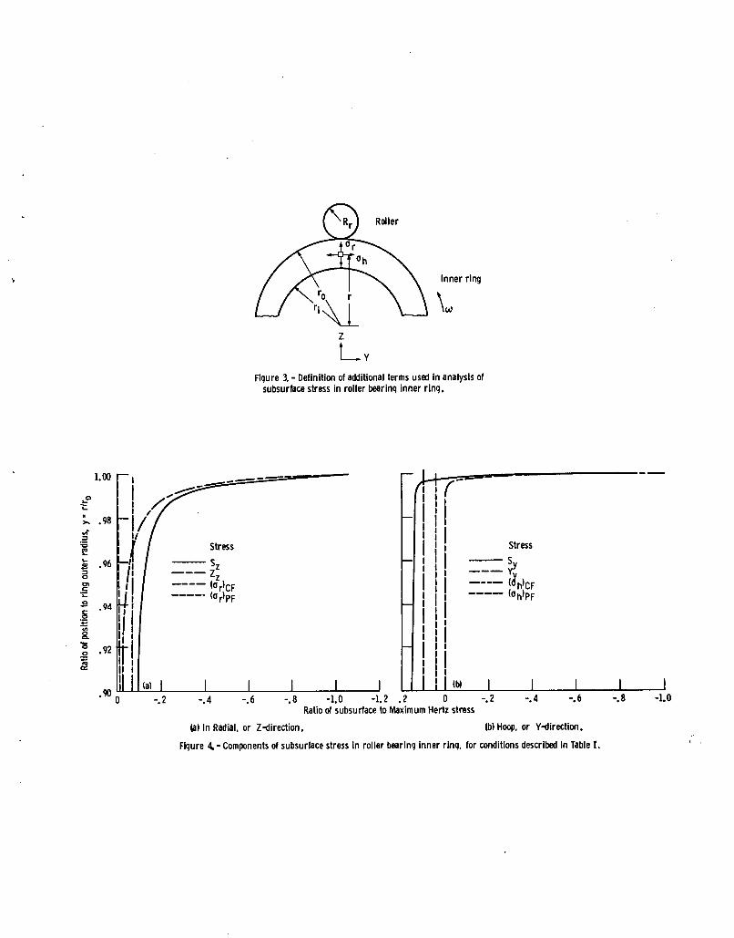
The relative values of subsurface stress are shown in figure 4 for the typical roller bearing inner-ring data given in table I. in the 2-direction is shown in figure 4(a) while the principal stress in the
The principal stress
10
Y-d i rec t ion i s shown i n f i g u r e 4(b). The s t ress values have been nondimen- s iona l i zed by t h e Her tz s t ress (Smax). Note t h a t y = 0.90 i s t h e inner rad ius and y = 1 i s t he ou ter rad ius o f t h e r i n g .
I n f i g u r e 4(a), t he s t ress due t o r i n g speed i s t he l a r g e s t component a t t h e i nne r surface, b u t t he subsurface compressive s t ress due t o the Her tz ian load ing becomes dominant as the outer (con tac t ) sur face i s approached. I n f i g u r e 4(b), t h e s t ress due t o r i n g speed i s again the l a r g e s t a t t he inner sur face and t h e s t ress f rom the press f i t i s I n f l u e n t i a l . speed i s h igh i n the example problem and t h a t t he pressure assumed f o r the press f i t i s probably moderate. However, t he compressive s t ress due t o the Her tz ian load ing becomes dominant as the ou ter sur face i s approached. The p r i n c i p a l s t ress Sy does remain t e n s i l e ( p o s i t i v e ) u n t i l about y = 0.995, which w i l l i n f l u e n c e the maximum shear s t ress .
Note t h a t t he r i n g
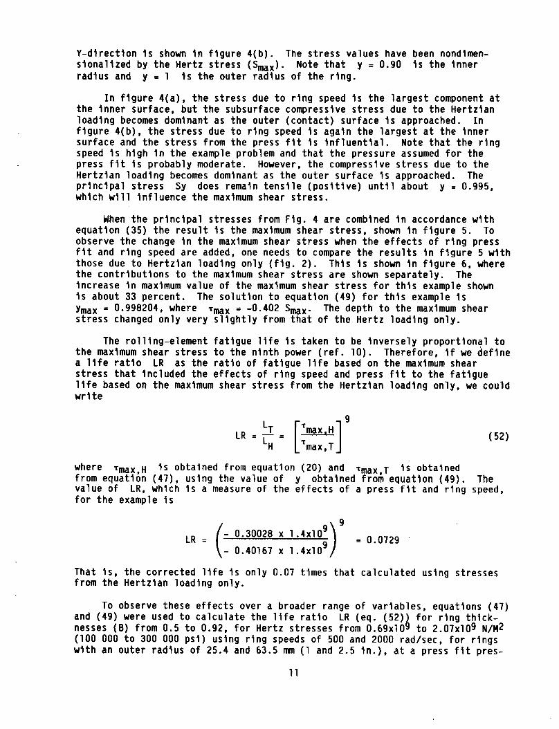
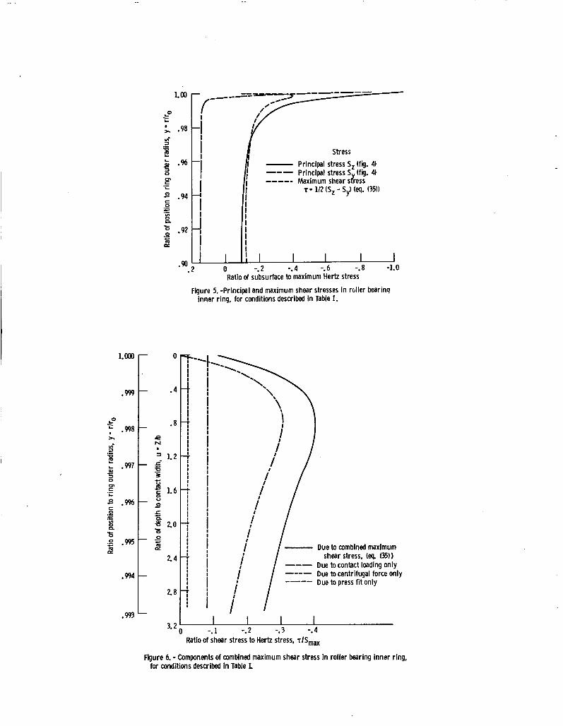
When the p r i n c i p a l stresses from F ig . 4 a re combined i n accordance w i t h equat ion (35) t h e r e s u l t i s t he maximum shear s t ress, shown i n f i g u r e 5. To observe t h e change i n the maximum shear s t ress when t h e e f f e c t s o f r i n g press f i t and r i n g speed a re added, one needs t o compare t h e r e s u l t s i n f i g u r e 5 w i t h those due t o Her tz ian load ing on ly ( f i g . 2). This i s shown i n f i g u r e 6, where the c o n t r i b u t i o n s t o t h e maximum shear s t ress a re shown separate ly . increase i n maximum value o f t he maximum shear s t ress f o r t h i s example shown i s about 33 percent. ymax = 0.996204, where s t ress changed on ly very s l i g h t l y f r o m t h a t o f t he Her tz load ing only.
The
The s o l u t i o n t o equat ion (49) f o r t h i s example i s Tmax = -0.402 Smax. The depth t o t h e maximum shear
The ro l l ing-e lement f a t i g u e l i f e i s taken t o be i n v e r s e l y p ropor t i ona l t o t h e maximum shear s t ress t o the n i n t h power ( r e f . 10). Therefore, i f we d e f i n e a l i f e r a t i o LR as the r a t i o o f f a t i g u e l i f e based on t h e maximum shear s t ress t h a t inc luded the e f f e c t s o f r i n g speed and press f i t t o the f a t i g u e l i f e based on t h e maximum shear s t ress f rom the Her tz ian load ing only, we could w r i t e
9 LT LR = - = LH max,T
where Tmax,~ i s obtalned from equat ion (20) and Tmax,~ I s obtalned from equat ion ( 4 7 ) , using the value o f y obtained f rom equat ion (49). The value o f f o r t h e example i s
LR, which i s a measure o f t he e f f e c t s of a press f l t and r i n g speed,
= 0.0729 - 0.30026 x 1 .4x109 L R = ( 9 - 0.40167 x 1 . 4 ~ 1 0
That i s , t h e cor rec ted l i f e i s on ly 0.07 times t h a t ca l cu la ted us ing stresses from the Her tz ian load ing only .
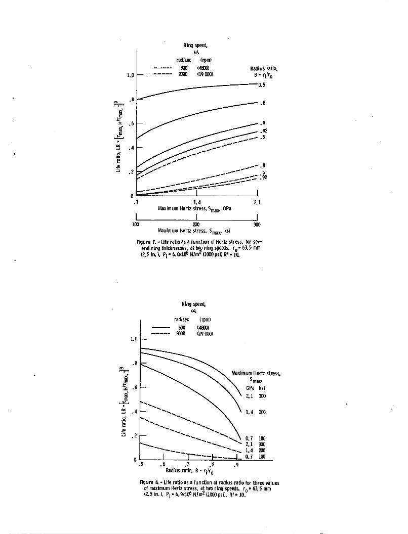
To observe these e f f e c t s over a broader range o f var iab les , equations (47) and (49) were used t o c a l c u l a t e the l i f e r a t i o LR (eq. (52) f o r r i n g t h i c k -
(100 000 t o 300 000 p s i ) us ing r i n g speeds o f 500 and 2000 rad/sec, f o r r i n g s w i t h an ou ter rad ius o f 25.4 and 63.5 mn ( 1 and 2.5 in . ) , a t a press f i t pres-
nesses (8 ) f rom 0.5 t o 0.92, f o r Her tz stresses from 0 .69~10 B t o 2.07~109 N/M2
11
sure o f 6 .9~106 N/M2 (1000 p s i ) , and w i t h a rad ius r a t i o R ' 10. The r e s u l t s a r e shown i n f i gu res 7 t o 10.
o f both 5 and
F igure 7, f o r a r i n g w i t h an ou ter rad ius o f 63.5 m (2.5 In . ) shows t h a t t he r e l a t i v e i n f l uence o f press f i t and r i n g speed on f a t i g u e l i f e diminishes as the Her tz s t ress i s increased, o r as the r i n g becomes th i cke r , o r as the r i n g speed i s decreased. F igure 8 shows the same data p l o t t e d aga ins t rad ius r a t i o . Several ca l cu la t i ons f o r the cond i t ions o f f i g u r e 7 were made w i t h R ' = 5 and t h e l i f e r a t i o r e s u l t s were the same. Increas ing the press f i t pressure would lower the values o f LR. The pressure used i n f i g u r e s 7 and 8 represent an i n te r fe rence f i t o f about 0.051 mn (0.002 in . ) on the diameter.
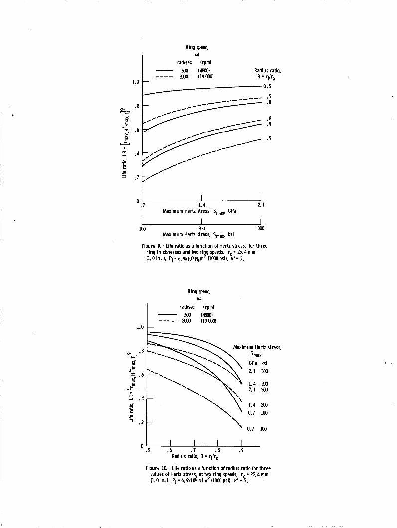
Figures 9 and 10 show the r e s u l t s obtained f o r an outer rad ius o f 25.4 mn
A comparison o f f i gu res 7 and 9 shows t h a t the l i f e r a t i o s w i t h the (1.0 i n . ) and an R ' o f 5. The l i f e r a t i o r e s u l t s w i t h an R ' o f 10 were the same. smal ler ou ter rad ius were genera l l y h igher than f o r t he corresponding l a r g e r r i ng , and were n o t so in f luenced by r i n g speed.
Since the re are many values o f LR o f 0.5 o r less, i t may be concluded t h a t t he press f i t and load ing due t o r i n g speed can have a s i g n i f i c a n t e f f e c t on the f a t i g u e l i f e ca lcu la ted f o r an i nne r - r i ng contact .
R o l l e r Bearing L i f e
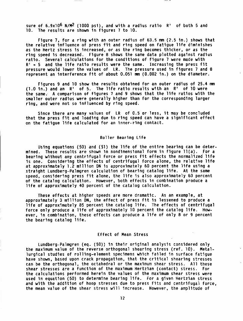
Using equations (50) and (51) the l i f e o f the e n t i r e bear ing can be de ter - mined. These r e s u l t s a re shown i n nondimensional form i n f i g u r e l l ( a ) . For a bear ing w i thou t any c e n t r i f u g a l f o rce o r press f i t e f f e c t s the normalized' l i f e i s one. Considering the e f f e c t s o f c e n t r i f u g a l f o rce alone, the r e l a t i v e l i f e a t approximately 1 .2 m i l l i o n DN I s approximately 60 percent the l i f e us ing a s t r a i g h t Lundberg-Palmgren c a l c u l a t i o n o f bear ing ca ta log l i f e . A t the same speed, consider ing press f i t alone, t he l i f e i s a l so approximately 60 percent o f t he ca ta log c a l c u l a t i o n . However, both e f f e c t s i n combination produce a l i f e o f approximately 40 percent o f the ca ta log ca l cu la t i on .
These e f f e c t s a t h igher speeds are more dramat ic. As an example, a t
The e f f e c t s o f c e n t r i f u g a l approximately 3 m i l l i o n DN, the e f f e c t o f press f i t i s lessened t o produce a l i f e o f approximately 85 percent the ca ta log l i f e . f o r c e on ly produce a l i f e o f approximately 10 percent the ca ta log l i f e . How- ever, i n combination, these e f f e c t s can produce a l i f e o f on ly 8 o r 9 percent t he bear ing ca ta log l i f e .
E f f e c t o f Mean S t r e s s
Lundberg-Palmgren (eq. (50 ) ) i n t h e i r o r i g i n a l ana lys is considered on ly the maximum value o f the reverse orthogonal shear ing s t r e s s ( r e f . 10). Metal- l u r g i c a l s tud ies o f ro l l ing-e lement specimens which f a i l e d i n surface f a t i g u e have shown, based upon crack propagation, t h a t t he c r i t i c a l shear ing stresses can be the orthogonal , the octahedral o r the maximum shear s t ress . A l l these shear stresses a re a func t i on of the maximum Her tz ian (contac t ) s t ress . For the ca l cu la t i ons performed here in the values o f the maximum shear s t ress were used i n equat ion (50) t o determine bear ing l i f e . For a given Her tz ian s t r e s s and w i t h the a d d i t i o n of hoop stresses due t o press f i t s and c e n t r i f u g a l force, the mean value o f the shear s t ress w i l l increase. However, the ampl i tude o f
12
t he maximum shear s t ress w i l l remain unchanged. For a g iven opera t ing condi- t i o n , the hoop stresses impose a steady o r s t a t i c s t ress . The steady o r s t a t i c s t ress d e f i n e t h e minimum shear s t ress. The maximum value o f shear s t ress equals the ampl i tude o f t he maximum shear s t ress p lus the s t a t i c s t ress . The mean s t ress can be de f ined as the average o f these two values.
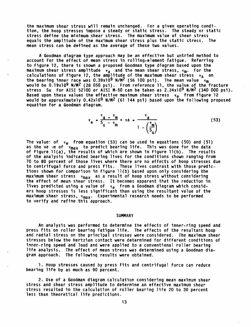
A Goodman diagram type approach may be an e f f e c t i v e bu t u n t r i e d method t o account f o r t h e e f f e c t o f mean s t ress i n ro l l ing-e lement fa t i gue . Re fe r r i ng t o f i g u r e 12, t he re i s shown a proposed Goodman type diagram based upon the maximum shear s t ress ampl l tude f a and t h e mean shear s t ress, Tm. For t h e ca l cu la t i ons o f f i g u r e 12, t he ampl i tude o f t he maximum shear s t ress the bear ing i nne r race was 0.39~109 N/M2 (56 100 p s i ) . would be 0.19~109 N/M2 (28 050 p s i ) . s t ress Su f o r A I S I 52100 o r A I S I M-50 can be taken as 2.34~109 N/M2 (340 000 p s i ) . Based upon these values the e f f e c t i v e maximum shear s t ress would be approximately 0 .42~109 N/M2 (61 144 p s i ) based upon the f o l l o w i n g proposed equat ion f o r a Goodman diagram.
f a on The mean value Tm
From reference 11, t h e value o f t he f r a c t u r e
f e from f i g u r e 12
The valuer o f as the va l e o f fmaX t o p r e d i c t bear ing l i f e . This was done f o r t he data o f f i g u r e l l ( a ) , t he r e s u l t s o f which a r e shown i n f i g u r e l l ( b ) . The r e s u l t s o f t he ana lys i s i nd i ca ted bear ing l i v e s f o r the cond i t ions shown ranging from 70 t o 80 percent o f those l i v e s where the re are no e f f e c t s o f hoop stresses due t o c e n t r i f u g a l f o rce and press f i t s . These l i v e s con t ras t w i t h those pred ic - t i o n s shown f o r comparison i n f i g u r e l l ( b ) based upon on ly consider ing the maximum shear s t ress as a r e s u l t o f hoop s t ress w i thou t cons ider ing the e f f e c t o f mean shear s t ress . I t becomes apparent t h a t t he reduc t ion i n l i v e s p red ic ted us lng a value o f Te f rom a Goodman diagram which consid- ers hoop stresses i s less s i g n i f i c a n t than us ing the r e s u l t a n t value o f t he maximum shear s t ress, fmax. t o v e r i f y and r e f i n e t h i s approach.
Te from equat ion (53) can be used i n equations (50) and (51)
fmax
Experimental research needs t o be performed
SUMMARY
An ana lys i s was performed t o determine the e f f e c t s o f I n n e r - r i n g speed and press f i t s on r o l l e r bear ing f a t i g u e l i f e . and r a d i a l s t ress on the p r i n c i p a l stresses were considered. The maximum shear stresses below the Her tz ian contact were determined f o r d i f f e . ren t cond i t ions o f i nne r - r i ng speed and load and were app l ied t o a convent ional r o l l e r bear ing l i f e ana lys is . gram approach. The f o l l o w i n g r e s u l t s were obtained.
The e f f e c t s o f t he r e s u l t a n t hoop
The e f f e c t o f mean s t ress was determined us ing a Goodman d ia -
1. Hoop stresses caused by press f i t s and c e n t r i f u g a l f o rce can reduce bear ing l i f e by as much as 90 percent.
2. Use o f a Goodman diagram c a l c u l a t i o n conslder ing mean maximum shear s t ress and shear s t ress ampl i tude t o determine an e f f e c t i v e maximum shear s t ress resu l ted i n the c a l c u l a t i o n o f r o l l e r bear ing l i f e 20 t o 30 percent less than t h e o r e t i c a l l i f e p red ic t i ons .
13
3. The depth t o t h e maximum shear s t ress remains r e l a t i v e l y unchanged by speed and press f i t , over t h e range ca lcu lated, f rom t h a t estab l ished by convent ional theory.
REFERENCES
1.
2.
3.
4.
5 .
6.
7.
8.
9.
10.
11.
Scott , R.L.; Kepple, R.K., and M i l l e r , M.H., "The E f f e c t o f Processing- induced Near-surface Residual Stress on B a l l Bearing Fatigue,@' Rolllng Contact Phenomena, J.B. B idwel l , Ed., E lsev ier , 1962, pp. 301-316.
Zaretsky, E.V., Parker, R.J., Anderson, W.J., and M i l l e r , S.T., " E f f e c t o f Component D i f f e r e n t i a l Hardnesses on Residual Stress and Rol l ing-Contact Fatigue," NASA TN-0-2664, 1965.
Alman, J.O.: E f f e c t s o f Residual Stress on R o l l i n g Bodies. R o l l i n g Contact Phenomena, J.B. B idwel l , Ed. E l sev ie r , 1962, pp. 400-424.
Townsend, D.P., and Zaretsky, E.V., " E f f e c t o f Shot Peening on Surface Fat igue L i f e o f Carburized and Hardened A I S 1 9310 Spur Gears," NASA TP-2047, AUg. 1982.
Czyzewski, T., I ' Inf luence o f a Tension Stress F i e l d Introduced i n t h e Elastohydrodynamic Contact Zone on Rol l ing-Contact Fatigue," Wear, Vol. 34, pp. 201-214, 1975.
Har r i s , T.A., R o l l i n g Bearing Analyses, John Wiley and Sons, Second Ed i t i on , NY, 1984.
Jones, A.B., "Analysis o f Stress and Def lect ions," Vol. I , New Departure Div., General Motors Corp, 1946.
Thomas, H.R., and Hoersch, V.A., Stresses due t o t h e Pressure o f One Elas- t i c S o l i d on Another," B u l l e t i n o f Engineering Experiment S t a t i o n No. 212, U n i v e r s i t y o f I l l i n o i s , 1930.
Faupel, J.H.: Engineering Design. John Wiley and Sons, Inc. 1964.
Lundberg, G.; and Palmgren, A., "Dynamic Capacity o f R o l l i n g Bearings,11 Acta Polytech. Scand, Mech. Engr. Ser., Vol. 1, no. 3, 1947.
Sachs, G., S e l l , R., and Brown, W.F., Jr., "Tension, Compression, and Fat igue Proper t ies o f Several Steels f o r A i r c r a f t Bearing Appl icat ions, Trans. ASTM, 1959, pp. 1-23.
1 4
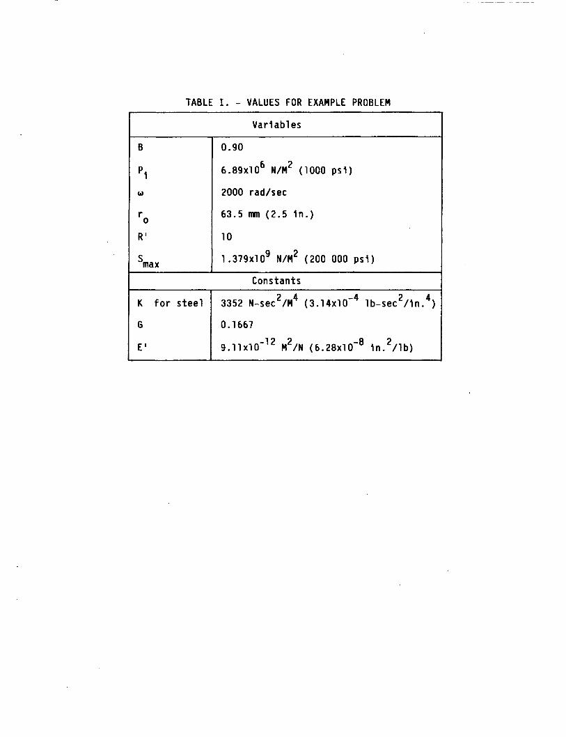
TABLE I . - VALUES FOR EXAMPLE PROBLEM
Var i ab1 es
B
pi
w
r
R '
0
0.90
6 . 8 9 ~ 1 0 ~ N/M2 (1000 p s i )
2000 rad/sec
63.5 M (2 .5 i n . )
10
1 .379x109 N/M2 (200 000 p s i )
Cons tan t s
K f o r s t e e l
G
E '
2 4 2 4 3352 N-sec /M
0.1667
( 3 . 1 4 ~ 1 0 - ~ lb-sec / I n . )
-12 2 2 1 9 . 1 1 ~ 1 0 M /N ( 6 . 2 8 ~ 1 0 - ~ i n . / l b )
Z
*.-Rectangular contact area X
zz Figure 1. - Principal stresses on elementary subsurface particle at depth Z under Hertzian pressure area.
,
Ratio of shear to Hertz stress, T / S , , , ~ ~
Fiqure 2 -Maximum shear stress as a function of depth below the surface, for Hertzian load- inq. Stress on Z-axis, below rectanqular pressure area.
1.00
L .9b 3 0
ol c .- L
s .94 0
VI 0 CL
.- .- c
.90
Inner ring
Fiqure 3. - Definition of additional terms used in analysis of subsurface stress in roller bearinq inner rinq.
I I I 0 -. 2 -. 4 -. 6 -. 8 -1.0 -1.2 . 2 0 -. 2 -. 4 -. 6 -. 8 -1.0
I
Ratio of subsurface to Maximum Hertz stress
b) In Radial, or Zdirection. (b) Hoap, or Ydirection.
Fiqure 4 - Components of subsurface stress in roller bearing inner rinq. for conditions described in Table I.
1.00
P - L
; .98 I,-- a
e e .96
P s .94
.- ‘CI
0
.- L
c 0
v) 0 eL
.- .- c c
.92 .- c 2
.90
i i i
-( --_-_- - - - - ------- I
-I I
I
I
I I I I
Stress
I
- Principal stress S , (rQ. 4) --- Principal stress S (fg. 4) Maximum shear s&ess i T = 112 6, - sy’ (eq. (35))
4
I I 1 I I I I
I
i 1 ! j i I j
1
I
i
Due to combined maximum shear stress, (eq, (35))
Due to contact loading only Due to centrifugal force Only Due to press f i t only
Ratio of shear stress to Hertz stress. i /Smax
Figure 6. - Components of combined maximum shear stress in roller bearing inner ring, for conditions described in Table L
4 0-
.E
.- E .- J
.7 1.4 Maximum Hertz stress. Smax, GPa
100 200 300 Maximum Hertz stress, Sma, ksi
Figure 7. - Life ratio as a function of Hertz stress, for sev- eral ring thidtnesses. a t two r ing speeds. ro 63.5 mm (25 in. 1, Pi - 6&14 Nlm2 (loo0 PSI) R' - 10,
Ring speed, a.
radlsec (rpml 500 Moo) ----- 2ooo (19000)
1. o I- GPa ksi 21 300
5 .4 1.4 200
.5 .6 .7 .a .9 Radius ratio, B - q / ro
Fqure 8 - Life ratio as a function of radius ratio for three values of maximum Hertz stress, at two r ing speeds. r O = 63.5 mm ( 2 5 in. h Pi = 6.9x10⁶ N\m2 (1000 psi). R' = 10.
1.0
Ring speed, w.
radlsec (rpm) - 500 ~48M)) Radius ratio, ---- 2Mx) (19000) B q/ r0 1 x- t 5 .6
x- m
CE. er A .4 0-
8
.- E A .2 .-
0.5
01 C.
0
! 1.4 21 0
.7 Maximum Hertz stress, Smax, GPa
100 200 300 Maximum Hertz stress, Smax. ksi
Fiqure 9. - Life ratio as a function of Hertz stress, for three r inq thicknesses and hvo r inq speeds. ro - 25.4 mrn (1.0 in. 1, Pi = 6.~106 N/m2 ~1000 psi). R' 5.
1.0
+$= .* J 2
t 5 .6 J
& I
4 .4 0-
e .- c
Ring speed, w.
radlsec (rpm) xx) (4x0) ---- 2ooo (19000) 1
Maximum Hertz stress,
-
'\ 0.7 100
0 .5 .6 .7 - 8 .9
Radius ratio, B - ri/ro
Fiqure la - Life ratio as a function of radius ratio for three values of Hertz stress, at two ring speeds. r = 25.4 mm (1.0 in. 1, Pi 6.9~106 N/m2 (loo0 psi), R' - 3.
'.Oo r Without corrections
.20
5ect of press f i t \ correction only
- I I I
c al 5 1.00 (a) Effect based on maximum shear stress, T~~~
Without corrections r
I- \ '.
0 5 10 15 20 25 3O~ld Inner r i ng speed, rpm
(b) Effect of both press f i t and r ing speed life corrections based on T~ and T ~ ~ .
Figure 1L - Effect of hoop stresses on the fatigue l i fe of 118-mm bore roller bearing. Rad al load 8900 N (2ooo Ib). Interference f i t pressure 6.89~1 J Nlm2 (lo00 psi). Maxi um Hertz stress at maximum loaded roller 1290 N l m P (187 o00 psi).
SU Mean stress,^,,,
fatigue life predictions to account for effects of hoop stresses.
Figure 12 - Proposed Goodman diagram for rolling-element
12. Government Accession No. I 3. Recipient's Catalog No. 1. Report No.
E f f e c t o f I n te r fe rence F i t s on R o l l e r Bearing Fat igue L i f e
7. Author@)
NASA TM-87165 5. Report Date 4. Title and Subtitle
January 1986 6. Performing Organization Code
505-33-7C 8. Performing Organization Report No.
9. Performing Organization Name and Address
Nat iona l Aeronautics and Space Admin is t ra t ion Lewis Research Center
2. Sponsoring Agency Name and Address
Cleveland, Ohio 44135
Harold H. Coe and Erwin V. Zaretsky IO. Work Unit No.
11. Contract or Grant No.
13. Type of Report and Period Covered
Tec hn i ca 1 Memorand um
I E-2516
Nat iona l Aeronautics and Space Admin is t ra t ion Washington, D.C. 20546
14. Sponsoring Agency Code
17. Key Words (Suggested by Author@))
6. Abstract
An ana lys i s was performed t o determine the e f f e c t s o f i nne r - r i ng speed and press f i t s on r o l l e r bear ing f a t i g u e l i f e . r a d i a l s t resses on the p r i n c i p a l stresses were considered. The maximum shear stresses below the Her tz ian contact were determined f o r d i f f e r e n t cond i t ions o f i n n e r - r i n g speed and load, and were app l ied t o a convent ional r o l l e r bear ing l i f e ana lys is . approach. Hoop stresses caused by press f i t s and c e n t r i f u g a l f o rce can reduce bear ing l i f e by as much as 90 percent. Use o f a Goodman diagram pred ic ted l i f e reduct ions o f 20 t o 30 percent. The depth o f the maximum shear s t ress remained v i r t u a l l y unchanged.
The e f f e c t s o f the r e s u l t a n t hoop and
The e f f e c t o f mean s t ress was determlned us ing a Goodman diagram
18. Distribution Statement
9. Security Ciasslf. (of this report) 20. Security Classif. (of this page) 21. No. of pages
Unc 1 ass i f i ed Unc lass i f i ed
Fat igue; R o l l l n g bearings; Stress analys is ; L i f e ana lys is
22. Price'
Unc lass i f i ed - un l lm l ted STAR Category 37
'For sale by the National Technical Information Service, Springfield, Virginia 221 61