Embed Size (px)
Citation preview

Effect of Infill Wall on the Seismic Behaviour of Steel
Framed Structures
Ashraf Muftah Lehweaj Milad
Submitted to the
Institute of Graduate Studies and Research
in Partial Fulfillment of the Requirements for the degree of
Master of Science
in
Civil Engineering
Eastern Mediterranean University
October 2015
Gazimağusa, North Cyprus

Approval of the Institute of Graduate Studies and Research
Prof. Dr. Cem Tanova
Acting Director
I certify that this thesis satisfies the requirements as a thesis for the degree of Master
of Science in Civil Engineering.
Prof. Özgür Eren
Chair, Department of Civil Engineering
We certify that we have read this thesis and that in our opinion it is fully adequate in
scope and quality as a thesis for the degree of Master of Science in Civil
Engineering.
Asst. Prof. Dr. Mürüde Çelikağ
Supervisor
Examining Committee
1. Asst. Prof. Dr.Tülin Akçaoğlu
2. Asst. Prof. Dr. Mürüde Çelikağ
3. Asst. Prof. Dr. Giray Özay
iii
ABSTRACT
Most of the structural steel frame design is carried out with the assumption that the
frame is bare and ignores the possible contribution of partition wall to the lateral load
resisting system. Whilst presence of partition walls can strengthen the frame against
lateral loads on the other hand it can make the frame stiff, which may reduce its
ductility. This may be more important for the braced frames where bracings are
designed to react freely to lateral loads and hence presence of partition walls may
hinder this action. There is very limited work in the literature on this important
subject. This thesis presents an experimental study on the behaviour of braced and
moment frames with and without infill walls when subject to lateral loads. For this
purpose, eight half-scale frame specimens were constructed by using two steel
columns and one beam members. Equal leg angles were used as cross bracing for the
braced frames only. To ascertain the impact of each specification, global drift
proportions are taken into account for each test frame and are compared with each
other. Test results showed that infill walls built of masonry blocks increase the rigidness of
structural frames, resist lateral loads and limit frame deflections. Experimental test results
reveal that the test frames having infilled walls had less damage than either the moment
frame or braced frame without infill walls.This attributed to the increased stiffness of frames
with infill walls.
Keywords: Lateral loads; Infill partition wall; Braced steel frame; Cross Bracing
systems; Moment frame

iv
ÖZ
Birçok yapısal çelik çerçeve tasarım esnasında çerçevenin içinin boş olduğu
varsayımıyla tasarlanır ve bölme duvarların yatay yük taşıma sistemine olası etkileri
gözönüne alınmaz. Bir yandan bölme duvarlar çelik çerçeveyi yatay yüklere karşı
daha güçlü yaparken diğer yandan da daha sert yaptığından sünekliğini azaltabilir.
Bölme duvarların çarprazlı çerçevelerde daha çok önemli olabilir, serbestçe hareket
ettiği varsayılan çarprazların hareketine engel olabilir. Bu önemli konu üzerine
yapılmış çok kısıtlı araştırmalar vardır. Bu tezde bölme duvarlı ve duvarsız, çarprazlı
ve rijit çerçevelerin yatay yükler altında davranışını deneysel olarak incelenmiş ve
sonuçları paylaşılmıştır. Bu gerekçeyle sekiz adet yarı ölçek çerçeve örneği iki adet
çelik kolon ve bir adet çelik kiriş kullanılarak imal edilmiştir. Eşit kenar köşebent
çarprazlarlı çerçevede kullanılmıştır. Her örneğin yatay yüklere karşı davranışının
etkisini görmek için global yatay yer değiştirme oranları biribiriyle karşılaştırılmıştır.
Sonuçlar bölme duvar kullanılan çerçevelerin daha rijit davrandığını ve yatay yüklere
karşı çerçeve yatay yer değitirmelerini kısıtladığını göstermiştir. Deney sonuçları rijit
veya çarprazlı bölme duvar içeren çerçevelerin yatay yük altında bölme duvarı
olmayan çerçevelere göre daha az hasar gördüğünü göstermiştir. Bölme duvarın çelik
çerçevelerin katılığını arttırdığından dolayı bu sonucun elde edildiği
düşünülmektedir.
Keywords: Yatay yükler; Bölme duvarlar; Çarprazlı çelik çerçeveler; Çarpraz
bağlantı sistemleri; Rijit çerçeveler

v
DEDICATION
I dedicate my study to my family and friends. A special feeling of gratitude to my
late loving mother, Mabrooka Mohammed and loving father Muftah Lehweaj whose
words of encouragement and precious advice ring in my ears. My sisters, who have
never left my side and are very special to me. I also dedicate this study to my friends
and extended family, who have supported me throughout the process of success. I
will always remember and appreciate all that they have done. I also dedicate this
work and special thanks to my brother Benmadi Milad, who has supported and
encouraged me throughout the entire master program. It is with the help of family
that I was able to make it here today.

vi
ACKNOWLEDGEMENT
Successfully finishing this thesis has only been possible with the help of Allah whom
has blissfully provided me with guidance. I thank Allah immensely for making it
possible for me to complete this project.
Secondly, I would like to accord my thanks to my supervisor Asst. Prof. Dr. Murude
Celikag for her immeasurable contribution to my academic knowledge and her
support academically.
I also wish to thank the staff of the Structural Engineering Laboratory at Eastern
Mediterranean University of Civil Engineering Department, especially Mr.Ogün
Kılıç for his professional assistance before and during the experiment, yet also for
the pleasant informal conversations during the breaks. I also would like to thank the
technicians at Güneş Metal Sanayi for their patience and hard work during the
fabrication of test frames.
Finally, and most importantly, I would like to thank my family, for their support,
encouragement, and patience. I thank them for listening to me and encouraging me in
difficult times without their patience and understanding, as well as financial support,
this thesis would not have been possible.

vii
TABLE OF CONTENTS
ABSTRACT ................................................................................................................ iii
ÖZ ............................................................................................................................... iv
DEDICATION ............................................................................................................. v
ACKNOWLEDGEMENT .......................................................................................... vi
LIST OF TABLES ...................................................................................................... xi
LIST OF FIGURES .................................................................................................. xiii
LIST OF SYMBOLS AND ABBREVIATIONS ..................................................... xvi
1 INTRODUCTION .................................................................................................... 1
1.1 Introduction ........................................................................................................ 1
1.2 Causes of Earthquakes ........................................................................................ 2
1.3 The Seismicity of the World............................................................................... 2
1.4 Significance of this Research ............................................................................. 4
1.5 Objective of this Study ....................................................................................... 4
1.6 Organization of the Thesis ................................................................................. 5
2 LITERATURE REVIEW.......................................................................................... 7
2.1 Introduction ........................................................................................................ 7
2.2 Background ........................................................................................................ 7
2.3 Lateral Load ....................................................................................................... 8
2.3.1 Earthquake Loads ........................................................................................ 8
2.3.2 Wind Loads .................................................................................................. 8
2.3.3 Story Drift .................................................................................................... 9
2.3.4 Story Displacement ...................................................................................... 9
2.4 Structural Design .............................................................................................. 10
viii
2.5 Moment Frames ................................................................................................ 10
2.6 Braced Frames .................................................................................................. 12
2.6.1 Concentrically Braced Frames ................................................................... 14
2.6.2 Ordinary Concentric Braced Frames ......................................................... 15
2.6.3 Special Concentric Braced Frames ............................................................ 16
2.6.4 K-Bracing................................................................................................... 16
2.6.5 Chevron Bracing ........................................................................................ 17
2.6.6 Eccentrically Braced Frames ..................................................................... 17
2.7 Seismic Performance of Concentrically Braced Frames (CBFs) ..................... 19
2.8 Frame with Infill Wall ...................................................................................... 20
2.9 Structural System of Masonry Infill Wall ........................................................ 21
2.10 Behavior of Masonry Infilled Steel Frames ................................................... 21
2.11 Possible Modes of Failure of Infill Walls ...................................................... 24
3 TESTING PROGRAM ........................................................................................... 26
3.1 Introduction ...................................................................................................... 26
3.2 Modelling, Analysis and Design of Test Frames ............................................. 26
3.3 Load Cases ....................................................................................................... 28
3.4 Analysis and Design of Test Frames ................................................................ 28
3.5 Material Properties and Steel Sections Used .................................................... 29
3.6 Experimental set-up .......................................................................................... 31
3.7 Instrumentation for Frame Tests ...................................................................... 32
3.8 Test Procedure .................................................................................................. 35
3.9 Connection Design of Test Frames .................................................................. 36
i. Pinned Connections for Moment Frame (major axis) ..................................... 36
ii. Flexible End Plate Connections for Moment Frame (minor axis).................. 36

ix
iii. Fin Plates Connection of Bracing Frame (major axis) .................................. 37
iv. Fin Plates Connection of Bracing Frame (minor axis) .................................. 37
v. Column Bases ................................................................................................. 38
3.9.1 Structural Bolts .......................................................................................... 40
4 EXPERIMENTAL RESULTS AND DISCUSSIONS ........................................... 42
4.1 Introduction ...................................................................................................... 42
4.2 Mechanical Properties of Steel Sections Used for Test Frames ....................... 43
4.3 Minor Axis Frame Tests ................................................................................... 45
4.3.1 Moment Frame without Infill Wall (MIN-MF1) ....................................... 46
4.3.2 Moment Frame with Infill Wall (MIN-MFIN2) ........................................ 49
4.3.3 Braced Frame without Infill Wall (MIN-BR3) .......................................... 52
4.3.4 Braced Frame with Infill Wall (MIN-BRIN4) ........................................... 55
4.4 Major Axis Frame Tests ................................................................................... 59
4.4. Moment Frame without Infill Wall (MAJ-MF5) ......................................... 60
4.4.2 Moment Frame with Infill Wall (MAJ-MFIN6) ........................................ 62
4.4.3 Braced Frame without Infill Wall (MAJ-BF7) .......................................... 65
4.4.4 Braced Frame with Infill Wall (MAJ-BFIN8) ........................................... 68
4.5 Discussion of Test Results ............................................................................... 71
4.5.1 Effect of Column Orientation on the Frame Action .................................. 71
4.5.1.1 Test Frames MAJ-MF5 and MIN-MF1 .................................................. 71
4.5.1.2 Test Frames MAJ-MFIN6 and MIN-MFIN2 ......................................... 72
4.5.1.3 Test Frames MIN-BR3 and MAJ-BF7 ................................................... 73
4.5.1.4 Test Frame MIN-BRIN4 and MAJ-BFIN8 ............................................ 74
4.5.2 Effect of Infill Wall on the Frame Action.................................................. 75
5 CONCLUSION AND RECOMMEDDATIONS .................................................... 78
x
5.1 Conclusion ........................................................................................................ 78
5.2 Recommendations ............................................................................................ 80
REFERENCES ........................................................................................................... 82
APPENDICES ........................................................................................................... 88
Appendix A: Details of Test Frames ...................................................................... 89
Appendix B: Frame Loading and the Support Frames ........................................... 97

xi
LIST OF TABLES
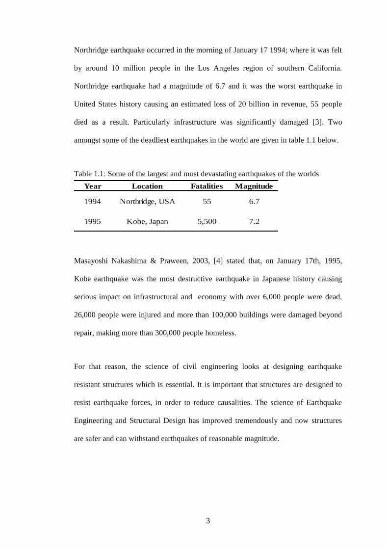
Table 1.1: Some of the largest and most devastating earthquakes of the worlds......... 3
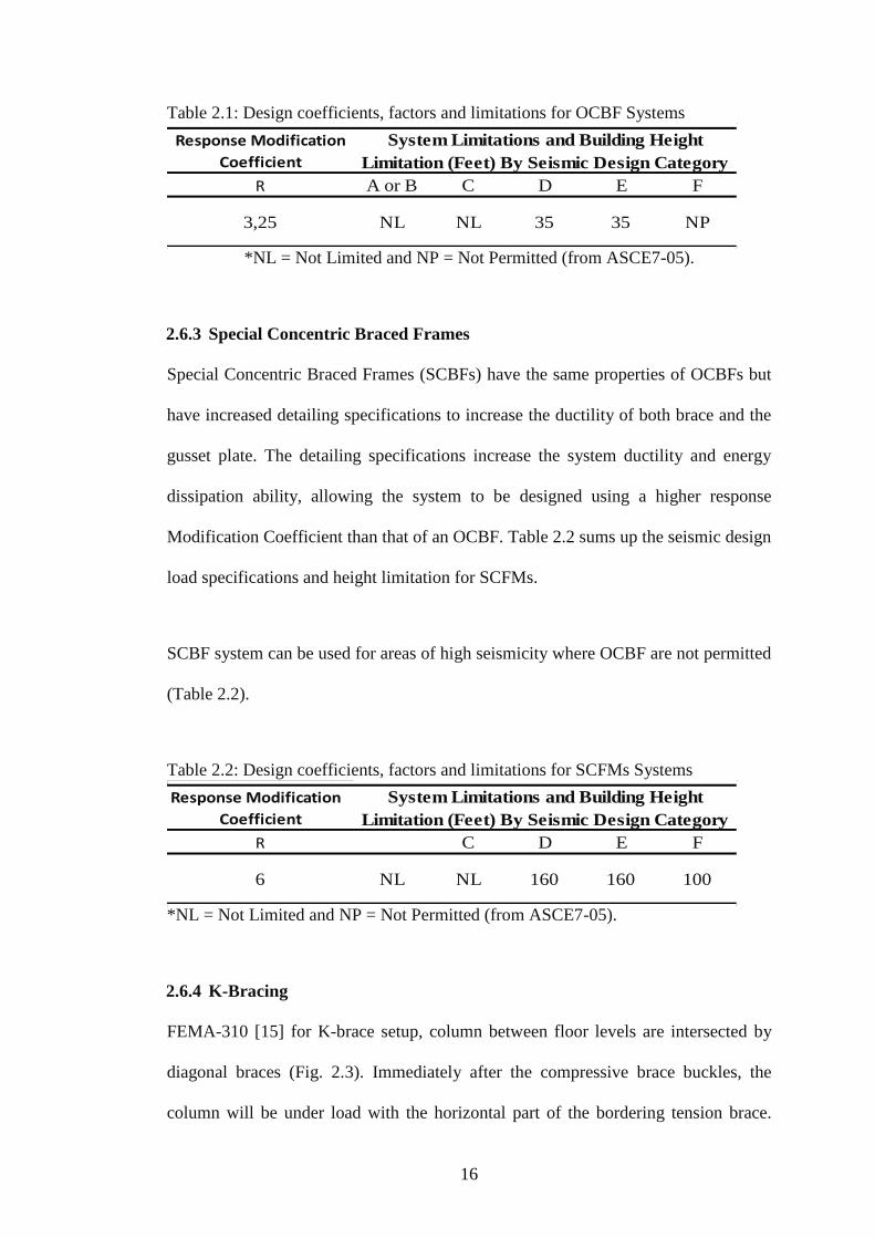
Table 2.1: Design coefficients, factors and limitations for OCBF Systems .............. 16
Table 2.2: Design coefficients, factors and limitations for SCFMs Systems............. 16
Table 3.1: Nominal values of the yield strength and the ultimate tensile strength
according to BS EN 10025:1993 ............................................................................... 29
Table 3.2: Steel section properties ............................................................................. 30
Table 3.3: Sections dimension of system frame......................................................... 30
Table 3.4: Bolt and nut dimensions [5]. ..................................................................... 41
Table 4.1: Key for the steel frame test numbers ........................................................ 43
Table 4.2: Mechanical properties of the tested steel sections .................................... 44
Table 4.3: Sections properties used in the test frame ................................................. 45
Table 4.4: Displacements and rotations measured at various locations for the moment
frame without infill wall (MIN-MF1) ........................................................................ 47
Table 4.5: Displacements and rotations measured at various locations for the moment
frame with infill wall (MIN-MFIN2) ......................................................................... 50
Table 4.6: Displacements and rotations measured at various locations for the braced
frame without infill wall (MIN-BR3) ........................................................................ 53
Table 4.7: Displacements and rotations measured at various locations for the braced
frame with infill wall MIN-BRIN4 ............................................................................ 56
Table 4.8: Displacements and rotations measured at various locations for the moment
frame without infill wall (MAJ-MF5) ........................................................................ 60
Table 4.9: Displacements and rotations measured at various locations for the
moment frame with infill wall (MAJ-MFIN6)........................................................... 63

xii
Table 4.10: Displacements and rotations measured at various locations for the braced
frame without infill wall (MAJ-BF7) ......................................................................... 66
Table 4.11: Displacements and rotations measured at various locations for the braced
frame with infill wall (MAJ-BFIN8) ......................................................................... 69

xiii
LIST OF FIGURES
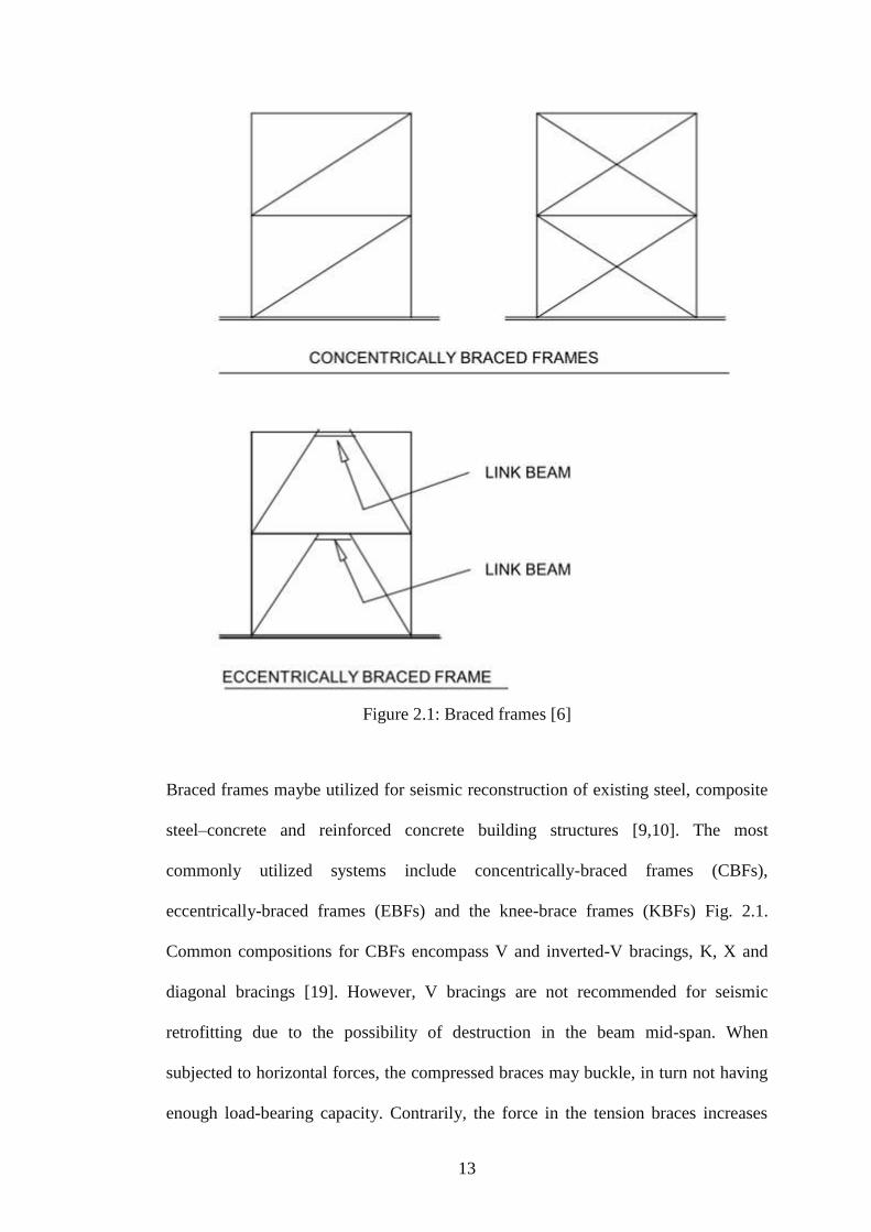
Figure 2.1: Braced frames [6] .................................................................................... 13
Figure 2.2: Typical braced frame configurations ....................................................... 15
Figure 2.3: Bracing Types .......................................................................................... 17
Figure 2.4: Eccentrically Braced Frames ................................................................... 18
Figure 2.5: Typical concentric bracing configurations .............................................. 20
Figure 2.6: Effect of masonry infill on the behavior of steel frame (results of
numerical analysis from (Zovkic, Sigmund, and Guljas 2013)) ................................ 23
Figure 2.7: Comparison of experimental results between solid infill wall and walls
with different types of window openings [31] ........................................................... 24
Figure 2.8: Diagonal strut model [32] ....................................................................... 25
Figure 3.1: Moment and braced frames without infill wall. ...................................... 28
Figure 3.2: Moment and braced frames with infill wall............................................. 28
Figure 3.3: Column, beam, and bracing dimension details of s ection for frame
system ......................................................................................................................... 30
Figure 3.4: Dimensions of BIMs block. ..................................................................... 31
Figure 3.5: Test frame set-up for major and minor axis (without infill wall). ........... 32
Figure 3.6: Test frame set-up for major and minor axis (with infill wall). ................ 32
Figure 3.7: Locations of LVDTs and load the major or minor axis for Moment
Frame without infill wall (MAJ-MF5, MIN-MF1). ................................................... 33
Figure 3.8: Locations of LVDTs and Load the major or minor axis for Moment
Frame with infill wall (MAJ-MFIN6, MIN-MFIN2). ................................................ 34
Figure 3.9: Locations of LVDTs and Load Cell on the major or minor axis for
Braced Frame (MAJ-BF7, MIN-BR3). ...................................................................... 34
xiv
Figure 3.10: Locations of LVDTs and Load Cell on the major or minor axis for
Braced Frame infill wall (MAJ-BFIN8, MIN-BRIN4). ............................................. 35
Figure 3.11: Geometric variables for major and minor axis of moment framed
connection .................................................................................................................. 37
Figure 3.12: Geometric variables for major and minor axis braced framed
connections. ................................................................................................................ 38
Figure 3.13: Moment frame column base plate design for major-minor (all dimension
are mm). ..................................................................................................................... 39
Figure 3.14: Braced Frame column base plate design for major-minor axis (all
dimension are mm). .................................................................................................... 40
Figure 3.15: Hexagon head structural bolts used in experimental tests. .................... 41
Figure 4.1: Minor axis frame and load direction for HE120B column section. ........ 45
Figure 4.4.2: Lateral load versus lateral displacement for test frame MIN-MF1. ..... 48
Figure A.1: Stiffener, plate and base plate detail. ...................................................... 89
Figure A. 2: (Cont.) ................................................................................................... 90
Figure A. 3: (Cont.) .................................................................................................... 91
Figure A. 4: Dimensions and holes detail of column, beam and bracing. ................. 92
Figure A. 5: Moment frame system, beam and column connection details. .............. 93
Figure A. 6: Braced frame system, beam, column and bracing connection details. .. 94
Figure A. 7: Moment frame system, base plate and column connection details. ....... 95
Figure A. 8: Braced frame system, base plate and column connection details. ......... 96
Figure B. 9: Set up of hydraulic jack with a capacity of 1000 kN. ........................... 97
Figure B. 10: Set up of test frame LVDTs. ................................................................ 98
Figure B.11 Set up of test frame MIN-MF1. ............................................................. 98
Figure B. 12: Set up of test frameMIN-MFIN2. ........................................................ 99

xv
Figure B. 13: Set up of test frame MAJ-MF5. ........................................................... 99
Figure B. 14: Set up of test frame MAJ-BF7. .......................................................... 100
Figure B. 15: Set up of test frame MIN-MFIN2. ..................................................... 100
xvi
LIST OF SYMBOLS AND ABBREVIATIONS
A is the Cross-section area of the section
B is the width of the section
H is the depth of section
hi is the length of the web
Iy is the moment of Inertia about Y-axis
Iz is the moment of Inertia about Z-axis
Lo is the initial lent of specimen before tensile test
Lf is the final length of specimen after the tensile test
L1 is legs of the angle
L2 is legs of the angle
M is the diameter of bolts
MIN-MF1 minor axis column moment frame without infill wall
MIN-MFIN2 minor axis column moment frame with infill wall
MIN-BR3 minor axis column braced frame without infill wall
MIN-BRIN4 minor axis column braced frame with infill wall
MAJ-MF5 major axis column moment frame without infill wall
MAJ-MFIN6 major axis column moment frame with infill wall
MAJ-BF7 major axis column braced frame without infill wall
MAJ-BFIN8 major axis column braced frame with infill wall
r is the root radius of section
tf is the web thickness
WpIy is the elastic modulus of the section about Y-axis
WpIz is the elastic modulus of the section about Z-axis

1
Chapter 1
1. INTRODUCTION
1.1 Introduction
Annually, there are many casualties due to earthquakes in different parts of the
world. Lateral stability is noted as one of the important problems of steel structures
specifically in the regions with high seismic hazard. Steel structures often face
difficulties in providing adequate strength and stiffness against such loading [1]. The
Kobe earthquake in Japan and the Northridge earthquake in USA were two examples
where there were damages to steel structures. Inadequate ductility level in steel
members and connections and lateral instability were among the main reasons of
structural failure. Therefore, during the last two decades there had been more intense
research into the ductility levels of frames, particularly when they are subjected to
lateral loads.
Jagadis and Doshi [2] stated that the major concern in the design of multistoried steel
building is the provision of an efficient lateral load resisting system along with a
good gravity load carrying system. They investigated the effect of using different
types of bracing systems on the lateral load resisting capacity of multi storied steel
buildings. For this purpose they uses Ground+15 stories steel building models with
same configuration but different bracing systems, such as Single-Diagonal, X
bracing, Double X bracing, K bracing, V bracing. A commercial software package

2
STAAD.Pro V8i was used for the analysis of steel buildings and different parameters
were compared.
Since bracing system is not the only method for lateral load resistance this research
was aimed at looking into the behaviour and ductility levels of half scale test frames
that have cross bracing, moment frame, with and without infill walls.
1.2 Causes of Earthquakes
Earthquake is the ground motion or movement caused by a sudden release of energy
in the earth’s crust called the lithosphere. It arises from stresses built up during
tectonic processes of plate movements. The earth's outermost layer, the lithosphere,
consists of several large and fairly stable slabs called plates, which have a depth of
80 km. Moving plates of the earth's surface account for most of the seismic activity
of the world. The boundaries of the lithospheric plates coincide with the geographical
zones, which experience frequent earthquakes. However, while the simple plate-
tectonic theory is an important one for a general understanding of earthquakes, it
does not explain all seismicity in detail, since devastating earthquakes sometimes
occur away from these boundaries [3].
1.3 The Seismicity of the World
It is estimated that approximately 6,000 earthquakes are detected annually
throughout the world. The number of minor earthquakes sensed by humans, without
infrastructure damage or injury, is approximately 450. An estimate of 15 events
yearly can be extremely damaging and deadly. Earthquakes in Northridge-California,
1994 and Kobe-Japan, 1995 were among the largest earthquakes that are particularly
important due to extensive damages to steel framed buildings [3].
3
Northridge earthquake occurred in the morning of January 17 1994; where it was felt
by around 10 million people in the Los Angeles region of southern California.
Northridge earthquake had a magnitude of 6.7 and it was the worst earthquake in
United States history causing an estimated loss of 20 billion in revenue, 55 people
died as a result. Particularly infrastructure was significantly damaged [3]. Two
amongst some of the deadliest earthquakes in the world are given in table 1.1 below.
Table 1.1: Some of the largest and most devastating earthquakes of the worlds
Year Location Fatalities Magnitude
1994 Northridge, USA 55 6.7
1995 Kobe, Japan 5,500 7.2
Masayoshi Nakashima & Praween, 2003, [4] stated that, on January 17th, 1995,
Kobe earthquake was the most destructive earthquake in Japanese history causing
serious impact on infrastructural and economy with over 6,000 people were dead,
26,000 people were injured and more than 100,000 buildings were damaged beyond
repair, making more than 300,000 people homeless.
For that reason, the science of civil engineering looks at designing earthquake
resistant structures which is essential. It is important that structures are designed to
resist earthquake forces, in order to reduce causalities. The science of Earthquake
Engineering and Structural Design has improved tremendously and now structures
are safer and can withstand earthquakes of reasonable magnitude.
4
1.4 Significance of this Research
Possible weaknesses of the strength and resistance of buildings are often against
wind and earthquake loads, which are mainly lateral loads. Therefore, researchers are
continuously working on the improvement of building resistance against such loads.
Over the years there had been many researches on the behavior of various types of
structural frames against lateral loads [5]. Another excellent approach towards
strengthening and stiffening buildings for lateral loads is bracing systems [5].
However, there are very limited researches on the effect of infill walls on the
behavior of frames [6].
Results from previous experiments reveal that these two components of building
which are in-filled walls and the shear wall increase the stiffness and strength of the
structure [7]. Majority of the research carried out were concentrated on the reinforced
concrete walls rather than brick, aerated blocks, concrete blocks, etc, [8].
The most common structural framing methods for steel framed buildings are moment
framed and braced framed. Often infill walls are also used for braced frames and
there is very limited research on the effect of infill wall on the behavior of bracings
and hence braced frames.
1.5 Objective of this Study
The main objective of this study is to investigate the contribution of BIMs block
infill walls on the structural behavior of steel cross-bracings and the structural frame
when it is subject to lateral loads. For this purpose an experimental test program is
scheduled to investigate this behaviour. After careful consideration of the past
literature on the subject the objective of this study was formed. Accordingly a typical

5
2-D frame model was selected, which represents a half model of a real size building
frame. [9] ETABS (Computers and Structures, 2002) a commercial computer
program for the analysis of structures, was used to analyse and design the frame.
Then eight frame tests were carried out to find out the behaviour of these frames
when subject to gravity and lateral loads.
1.6 Organization of the Thesis
The following outline gives the general content of the thesis and a rational
arrangement by which the objectives stated in the previous section are fulfilled,
investigated and presented.
Chapter 1 provides a general introduction on the Nature of earthquake ground
motions in Kobe and Northbridge, and significance and hence the objective of study
is also presented.
Chapter 2 provides an overview of engineering literature and research on moment
frame and braced frames, and the behaviour of infill walls on steel frame.
Chapter 3 provides an overview of the design process through experimental data.
This chapter will include calculations, models, analysis and design, test specimens
and the load cases that this thesis will be dealing with.
In Chapter 4, there is discussion and analysis of the results obtained from
experimental tests which will be shown in more detail. The influence of BIMs block
infill walls, effect of major and minor axis stiffer and their relative impact on lateral
load behavior are examined by the investigation of two models.

6
Lastly, conclusion and recommendations for future studies are presented in chapter 5.

7
Chapter 2
2. LITERATURE REVIEW
2.1 Introduction
Over the years, failure and collapse of buildings in earthquake zones has been
studied by engineers. Therefore, there is need to find a feasible solution towards
increasing the strength and ductility of buildings in such areas. This research was
done so as to highlight the effect of infill walls on the behaviour of steel braced and
moment frames, in particular, lateral displacement and ductility of such frames when
subjected to horizontal wind or earthquake loading. For this reason, moment and
braced 2-dimensional frames were used with and without infill walls and beams
framing into columns flange and web to find the effect of infill wall on such frames.
2.2 Background
This chapter presents a literature review about resistance of various structural steel
framing systems to earthquake loads and the contribution of infill walls to such
systems in resisting earthquake loads.
With advances in science and technology, steel framed structures are becoming
crucial in modern architecture. Some of the advantages of using steel framing for
structures include: high strength, long spans, ductility, light weight, etc. Steel framed
structure are considered as one of the most resistant materials in seismic conditions is
believed to be a steel frame. Nevertheless over a 100 building steel structure frames
in the Northridge that occurred in United States and Kobe earthquake in Japan

8
suffered major damage and this drew attention from experts worldwide to study this
phenomenon. Accordingly, the importance on research of the seismic performance of
steel frame has significantly increased. A serious study was undertaken of a two-
story steel frame model with ANSYS Software, and the analysis of the steel frame in
different earthquake response. The result show that the steel frame structure has good
seismic performance [10].
2.3 Lateral Load
According Kapse and Shinde [11], the lateral loads closely resemble live loads,
who’s main horizontal force component is acting on different members of structure.
Analysis of lateral force effects due to wind and earthquake loads is usually done as
an equivalent static load in a lot of forms of high rise buildings.
2.3.1 Earthquake Loads
Every year storms case many structural damages and loss of life. In some regions
earthquakes occur more frequently. It is an instantaneous lateral movement in the
ground under a structure that may shift in any direction and the horizontal
components of this movement creates a wave action which usually transferred
vertically to the structure. Earthquake loads have more consistence than the wind
load. The stiffness, mass of the structure, and the motion of the earth surface causes
changes in the magnitude of an earthquake because of seismic forces. Modifying
location of building, importance factor, type of soil, and achieving good construction
practices may help in resisting these lateral forces [11].
2.3.2 Wind Loads
Wind loads are the most common lateral loads. Magnitude of force is directly
proportional with the overall height and shape of the structure and it also acts
externally but creates internal pressure or suction. The design of the structure should
9
be in such a way that the effective surface area subjected to wind must effectively be
minimized. Wind generates positive pressure on the windward side and a negative
pressure on the leeward side when there is resistance from the building. Factors that
affect the wind load include the geographical conditions, height, surface area of
exposure, nearby structures, building shape and size, winds direction, wind velocity
and pressures associated with architectural design. It should be noted that the wind
loads, as well as the pressure applied on the wall and roof elements, should be static
and uniform [11].
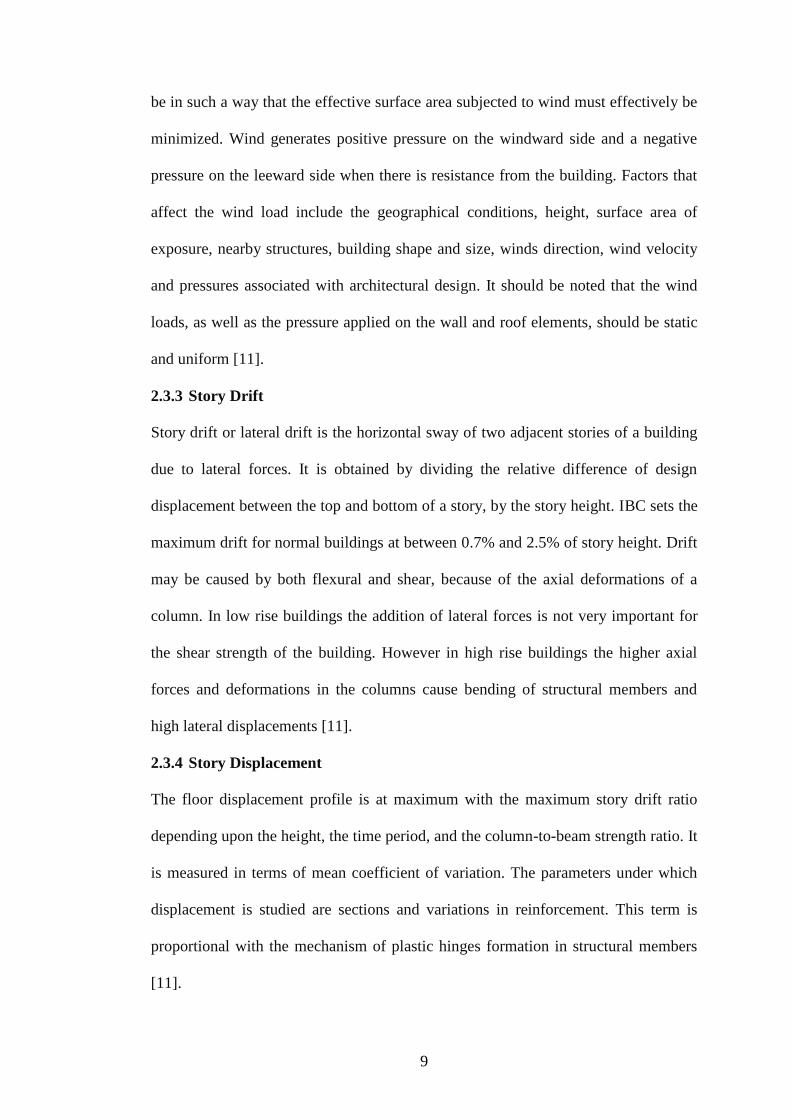
2.3.3 Story Drift
Story drift or lateral drift is the horizontal sway of two adjacent stories of a building
due to lateral forces. It is obtained by dividing the relative difference of design
displacement between the top and bottom of a story, by the story height. IBC sets the
maximum drift for normal buildings at between 0.7% and 2.5% of story height. Drift
may be caused by both flexural and shear, because of the axial deformations of a
column. In low rise buildings the addition of lateral forces is not very important for
the shear strength of the building. However in high rise buildings the higher axial
forces and deformations in the columns cause bending of structural members and
high lateral displacements [11].
2.3.4 Story Displacement
The floor displacement profile is at maximum with the maximum story drift ratio
depending upon the height, the time period, and the column-to-beam strength ratio. It
is measured in terms of mean coefficient of variation. The parameters under which
displacement is studied are sections and variations in reinforcement. This term is
proportional with the mechanism of plastic hinges formation in structural members
[11].
10
2.4 Structural Design
The determination of the structural design of a high rise building would ideally
include the extensive selection and arrangement of the structural elements to
efficiently counteract the different combinations of gravity and horizontal loading.
Factors that have to be considered in determining the structural form comprise of the
internal planning, the material, method of construction, the nature and magnitude of
horizontal loading [12].
Use of steel frame has been extensive in the United States for mid- to high-rise
structures. Majority of systems constructed before 1994 included steel moment
resisting frames that provided lateral resistance during an earthquake. Northridge
Earthquake of 1994 and Hyogoken–Nanbu Kobe Earthquake led to unanticipated
damage to most of these systems because of fracture of welded beam-to- column
connections that led to undesirable large lateral displacements [13].
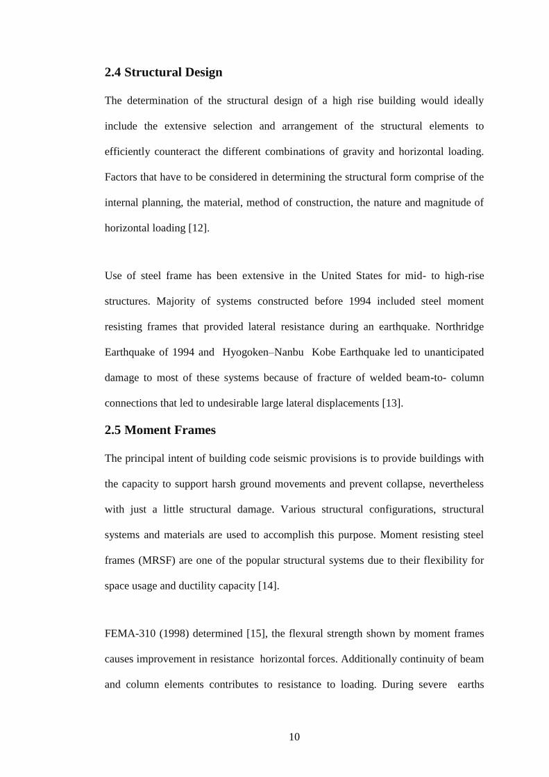
2.5 Moment Frames
The principal intent of building code seismic provisions is to provide buildings with
the capacity to support harsh ground movements and prevent collapse, nevertheless
with just a little structural damage. Various structural configurations, structural
systems and materials are used to accomplish this purpose. Moment resisting steel
frames (MRSF) are one of the popular structural systems due to their flexibility for
space usage and ductility capacity [14].
FEMA-310 (1998) determined [15], the flexural strength shown by moment frames
causes improvement in resistance horizontal forces. Additionally continuity of beam
and column elements contributes to resistance to loading. During severe earths
11
movement, a structural system that possess appropriate dimensions/ specifications
energizes plastic hinges which accommodate the implied force there by equipper the
overall system to tolerate the displacement. The serial loads aren’t always anticipated
during design and calculation. Present day moment frames, the locations of
maximum seismic moment are at the ends of beams and columns and this design
allows inelastic characteristics that are related to plastic hinging when considered in
a successive manner of layers and reversible loads. "Special moment frames" whose
details are configured to ductile sensitivity. Frames that do not have particular
seismic capacity extract support from the redundant strength incorporate in the
system. For ordinary moment frames, a sudden brittle mechanism will cause failure,
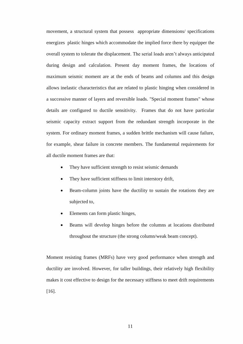
for example, shear failure in concrete members. The fundamental requirements for
all ductile moment frames are that:
They have sufficient strength to resist seismic demands
They have sufficient stiffness to limit interstory drift,
Beam-column joints have the ductility to sustain the rotations they are
subjected to,
Elements can form plastic hinges,
Beams will develop hinges before the columns at locations distributed
throughout the structure (the strong column/weak beam concept).
Moment resisting frames (MRFs) have very good performance when strength and
ductility are involved. However, for taller buildings, their relatively high flexibility
makes it cost effective to design for the necessary stiffness to meet drift requirements
[16].

12
2.6 Braced Frames
According, Tafheem & Khusru [17] advocated that Steel braced frame is one of the
structural systems used to resist lateral loads in multistory buildings. Among the
advantages of steel bracing are economical, easy to erect, occupies less space and has
flexibility to design to satisfy the required strength and stiffness. Braced frames are
commonly meant to resist lateral loads but braces can interfere with architectural
features. The steel braces commonly installed vertically aligned spans. This system
allows obtaining a large increase of stiffness with a minimal added weight.
Therefore, it is very effective for existing structure for which the poor lateral
stiffness is the main problem. To increase stiffness and stability of the structure
generally bracings are used to resist lateral loading and displacement, significantly.
13
Figure 2.1: Braced frames [6]
Braced frames maybe utilized for seismic reconstruction of existing steel, composite
steel–concrete and reinforced concrete building structures [9,10]. The most
commonly utilized systems include concentrically-braced frames (CBFs),
eccentrically-braced frames (EBFs) and the knee-brace frames (KBFs) Fig. 2.1.
Common compositions for CBFs encompass V and inverted-V bracings, K, X and
diagonal bracings [19]. However, V bracings are not recommended for seismic
retrofitting due to the possibility of destruction in the beam mid-span. When
subjected to horizontal forces, the compressed braces may buckle, in turn not having
enough load-bearing capacity. Contrarily, the force in the tension braces increases

14
constantly approaching yield strength and eventually strain-hardening. The net result
is an unbalanced force concentrated at the brace-to-beam connection [20]. The
effects on the beam, e.g. additional bending and shear, should be added to those due
to gravity loads [21]. Alternatively, the unbalanced force in the beams may be
eliminated through ad hoc bracing configurations, such as macro-bracings, e.g. two,
three stores X-bracings or V-bracings with a zipper columns [22].
2.6.1 Concentrically Braced Frames
Concentric bracing is known to increase lateral drift and reduce the frame stiffness
[17]. Although increase in the stiffness may attract a larger inertia force due to
earthquake. Furthermore, while the bracings decrease the bending moments and
shear forces in columns, they tend to increase the axial compression in the
columns to which they are connected.
Concentrically braced structures continue to be used as lateral load resisting systems.
As new systems and design approaches are developed there is anticipation of
increase in their use. Structural damages during the past earthquakes suggest that
braced systems may perform poorly due to their limited ductility and energy
dissipation. Even though there has been an increase in the use of braced frame
systems, failure of the connection between the braces and the frame can cause
unbalanced behavior of the brace in tension and compression, [23].
Concentrically braced frames (CBF) withstand displacement and lateral forces
mostly through the stiffness and axial strength of the brace members [24]. In CBF’s,
the neutral axis of the columns, beams and braces relate to common point known as a
work point. CBF’s have different arrangements, some of which are shown in Figure
2.2.

15
There are two types of concentrically braced frame systems: Ordinary Concentric
Braced Frames (OCBFs) and Special Concentric Braced Frames (SCBFs).
Figure 2.2: Typical braced frame configurations.
2.6.2 Ordinary Concentric Braced Frames
Ordinary Concentric Braced Frames (OCBFs) are expected to give little inelastic
deformation and are designed using higher seismic forces to counter their limited
ductility. They are suitable for small buildings in areas without much seismicity, due
to their simple design and detailing requirements. ASCE Minimum Design Loads for
Buildings and Other structures (ASCE 7-02) specifies the seismic design load
requirements and height limitations for OCBF which is summarized in Table 2.1.
16
Table 2.1: Design coefficients, factors and limitations for OCBF Systems
Response Modification
Coefficient
R A or B C D E F
3,25 NL NL 35 35 NP
System Limitations and Building Height
Limitation (Feet) By Seismic Design Category
*NL = Not Limited and NP = Not Permitted (from ASCE7-05).
2.6.3 Special Concentric Braced Frames
Special Concentric Braced Frames (SCBFs) have the same properties of OCBFs but
have increased detailing specifications to increase the ductility of both brace and the
gusset plate. The detailing specifications increase the system ductility and energy
dissipation ability, allowing the system to be designed using a higher response
Modification Coefficient than that of an OCBF. Table 2.2 sums up the seismic design
load specifications and height limitation for SCFMs.
SCBF system can be used for areas of high seismicity where OCBF are not permitted
(Table 2.2).
Table 2.2: Design coefficients, factors and limitations for SCFMs Systems
Response Modification
Coefficient
R C D E F
6 NL NL 160 160 100
System Limitations and Building Height
Limitation (Feet) By Seismic Design Category
*NL = Not Limited and NP = Not Permitted (from ASCE7-05).
2.6.4 K-Bracing
FEMA-310 [15] for K-brace setup, column between floor levels are intersected by
diagonal braces (Fig. 2.3). Immediately after the compressive brace buckles, the
column will be under load with the horizontal part of the bordering tension brace.

17
Large mid height requires which might compromise the balance of the column and
vertical reinforcement of the building will be induced.
Generally columns are not modelled to fight against this force. The danger to the
vertical support modelling creates unwanted bracing setting.
Figure 2.3: Bracing Types
2.6.5 Chevron Bracing
Figure 2.3 shown the chevron braces and are one of the most economical in terms of
fabrication and erection costs versus structural effectiveness, and the most
accommodating in terms of flexibility for locating door and window openings was
derived by Bubela, 2000 [25].
2.6.6 Eccentrically Braced Frames
Eccentrically braced frames are intentionally located away from joints and their
connections cause shear and flexure on the system. It is modelled to force a
concentration of inelastic movement at expected position which inturn regulate the
nature of the framework. Nowadays eccentrically braced frames are modelled with
stern control on the system dimensions and important out-of-plane bracing at the
links to make sure the frame operates like planned. The eccentrically braced frame is
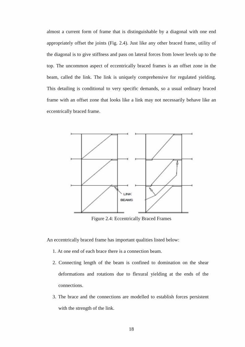
18
almost a current form of frame that is distinguishable by a diagonal with one end
appropriately offset the joints (Fig. 2.4). Just like any other braced frame, utility of
the diagonal is to give stiffness and pass on lateral forces from lower levels up to the
top. The uncommon aspect of eccentrically braced frames is an offset zone in the
beam, called the link. The link is uniquely comprehensive for regulated yielding.
This detailing is conditional to very specific demands, so a usual ordinary braced
frame with an offset zone that looks like a link may not necessarily behave like an
eccentrically braced frame.
Figure 2.4: Eccentrically Braced Frames
An eccentrically braced frame has important qualities listed below:
1. At one end of each brace there is a connection beam.
2. Connecting length of the beam is confined to domination on the shear
deformations and rotations due to flexural yielding at the ends of the
connections.
3. The brace and the connections are modelled to establish forces persistent
with the strength of the link.

19
4. Lateral bracing is given to avoid out-of-plane beam rearrangement that
would disturb the expected result.
Frequently when frames comprise the whole lateral force opposing modelling
eccentrically braced frames are utilized. A few high rise buildings, eccentrically
braced frames are added as stiffening members to assist regulate drift in moment
resisting steel frames.
2.7 Seismic Performance of Concentrically Braced Frames (CBFs)
Lateral load resisting systems are needed in most buildings to withstand horizontal
forces, static or dynamic, due to wind pressure or seismic accelerations [25]. For
steel structures there are two very popular systems, moment resisting frames (MRFs)
and CBFs are, each with their own associated costs and benefits.
MRFs work better in terms of strength and ductility. However, for high rise
structures, their relatively high flexibility makes it costly to design for the necessary
stiffness to reach drift requirements have been proposed by Mazzolani, F.M et al
[16]. Adding on, moment connections are more expensive than simple connections in
braced frames because of the particular detailing needed for high ductility as well as
the substantial amount of welding involved. Welded connections, especially those
done on-site, are likely to fracture because of irregularities in the welds. Due to their
exceptional energy absorbing qualities MRFs were the framing system selected in the
United States in high-risk seismic zones. The overall damage to welded MRF
connections during the 1994 Northridge earthquake in California seriously destroyed
this belief, which resulted in an extensive research and development project to fix the
design, detailing, fabrication and inspection of these connections (SAC, 1995).

20
When compared to other systems, CBFs have very good strength and stiffness and
effortlessly reach rigidity requirements, however, have less ductility than MRFs [25].
CBFs are widely utilized in low-medium- and high-rise construction and can be
designed in a number of bracing configurations, including cross (X-) bracing,
diagonal bracing, K-bracing, V-bracing and chevron (inverted V-) bracing (Figure
2.5).
Figure 2.5: Typical concentric bracing configurations
2.8 Frame with Infill Wall
Infill wall means partition wall that consists of a kind of masonry. Infill walls have
different varieties, such as brick masonry infill wall, concrete infill wall, timber
framed infill walls, light steel framed infill walls. The infill material is intended not
to take part in transmission of any overcoming loads to the structural system. But the
research and analysis results showed that the use of masonry infill walls constructed
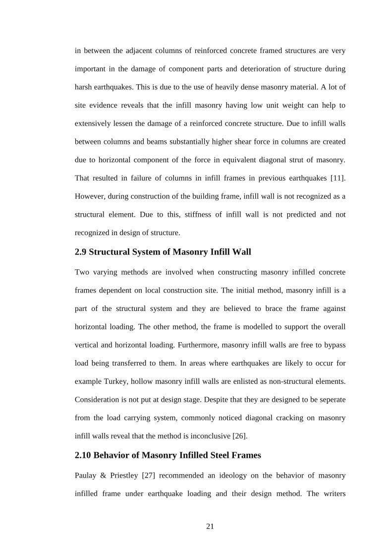
21
in between the adjacent columns of reinforced concrete framed structures are very
important in the damage of component parts and deterioration of structure during
harsh earthquakes. This is due to the use of heavily dense masonry material. A lot of
site evidence reveals that the infill masonry having low unit weight can help to
extensively lessen the damage of a reinforced concrete structure. Due to infill walls
between columns and beams substantially higher shear force in columns are created
due to horizontal component of the force in equivalent diagonal strut of masonry.
That resulted in failure of columns in infill frames in previous earthquakes [11].
However, during construction of the building frame, infill wall is not recognized as a
structural element. Due to this, stiffness of infill wall is not predicted and not
recognized in design of structure.
2.9 Structural System of Masonry Infill Wall
Two varying methods are involved when constructing masonry infilled concrete
frames dependent on local construction site. The initial method, masonry infill is a
part of the structural system and they are believed to brace the frame against
horizontal loading. The other method, the frame is modelled to support the overall
vertical and horizontal loading. Furthermore, masonry infill walls are free to bypass
load being transferred to them. In areas where earthquakes are likely to occur for
example Turkey, hollow masonry infill walls are enlisted as non-structural elements.
Consideration is not put at design stage. Despite that they are designed to be seperate
from the load carrying system, commonly noticed diagonal cracking on masonry
infill walls reveal that the method is inconclusive [26].
2.10 Behavior of Masonry Infilled Steel Frames
Paulay & Priestley [27] recommended an ideology on the behavior of masonry
infilled frame under earthquake loading and their design method. The writers
22
mentioned despite the fact that overall lateral load capacity may be increased this
will change the structural reaction and attract unwanted forces to various parts of the
structure with an unbalanced arrangement. This in effect will lead to masonry infill
wall causing structural deficiencies. However, from the recommendations of other
studies [28], investigations of the behavior of masonry infilled wall date back to over
50 years but there is no clear approach to design these structures as with other
common structural types. In case of large horizontal loads it has been observed that
infill wall had poor behavior especially under seismic loads.
A typical example of the masonry infill walls influence on the behaviour of one-bay
steel frame can be seen in Fig. 2.6. The masonry infill panel was modelled by linear
and nonlinear equivalent compression strut models and nonlinearity was included by
appropriate spring models. Results of the push-over analysis indicated the infill walls
suitable influence at small drifts increasing the structural stiffness and strength.
However, after the peak value was reached there was damage to the masonry and the
panel frame became weaker as clearly shown in the graph below. The consequences
were significant degradation of stiffness and strength and only low- to medium
displacement ductility’s could be achieved. The bare steel frame, on the other hand,
had high possible ductility. The behaviour modes, of infilled and bare steel frames
are different under horizontal loading.
According, Liu & Manes [29] mostly mansory walls are used to infill concrete or
steel frames optionally as walls to divide open space interior of the structure or as a
cover for the building outside. But, a shortage of scientific data on the actual amount
of infill wall-frame synergy is observed. As a result a design procedure where
masonry infills are frequently seen as non-structural elements and bounding frames

23
are intended for both gravity and lateral loading [1]. The idea rooted on this method
might end up expensive. However, if masonry infill walls were constructed with the
objective to take part in the load sharing with the bounding frame, not considering
the input of the infill wall to the stiffness and strength of the frame then this system
may cause an unsafe design. Infill walls extremely stiffen the frame system, which
can be destructive to lateral stability of the frame by attracting larger forces [30].
Figure 2.6: Effect of masonry infill on the behavior of steel frame (results of
numerical analysis from (Zovkic, Sigmund, and Guljas 2013)).
According, Maheri, Kousari, and Razazan (2003) [31] confirmed that, the frame has
been investigated with and without openings. The frame with brick masonry infill
wall and having modulus values ranging between 500MPa to 8000MPa were
analyzed. The material density and possion’s ratio used for RC members, masonry
and link are (2500 Kg/m3, 0.20), (1920Kg/m3, 0.18) and (zero*, 0.2) respectively.
Three combinations have been compared according to their stiffness i.e., solid infill,
1D2W and 1D1W. It was seen that there was decrease in the stiffness (i.e., up to

24
49%). For the condition of 1DW2 and 1D1W, for all the moduluses, there was a
decrease in stiffness of an average of 50% and 18% respectively. Similarly, the
comparison was done between the solid infill, 1DW2 and 1D1W as in Fig 2.7.
Figure 2.7: Comparison of experimental results between solid infill wall and walls
with different types of window openings [31].
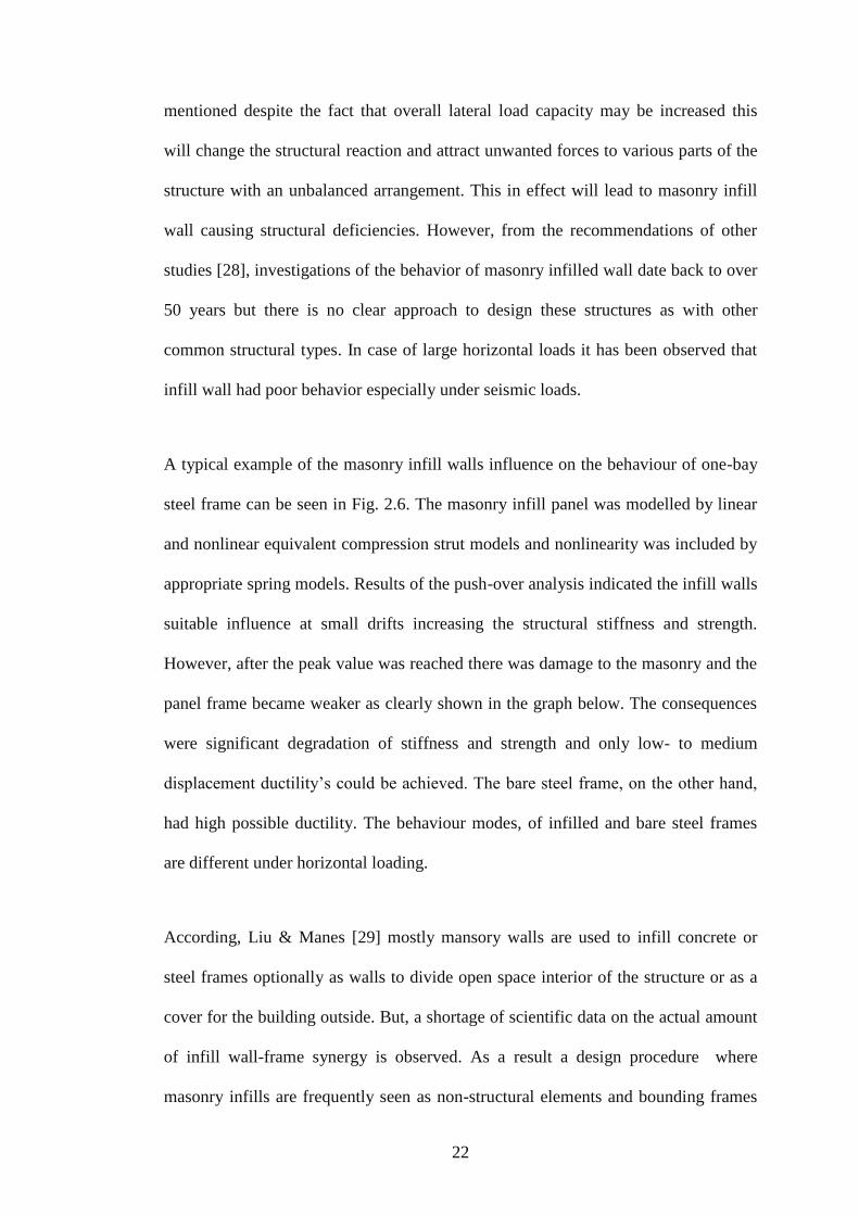
2.11 Possible Modes of Failure of Infill Walls
Ozturk [26] Proposed a design method on diagonally braced frame principle for
infilled frame. There were three possible ways of failure for infill walls where the
first one was crushing of corner of infill, shear along masonry, and diagonal cracking
through masonry. An assumption was made for theadequate width of diagonal
compression strut as the same as one-tenth of the diagonal length of the infill panel
as shown in the diagram below. The adequate width will be assumed as 𝑤 =1
10𝑑
(Fig. 2.8). At the first design phase, the frame has to be modelled on the basis of the
gravity loading.
25
Figure 2.8: Diagonal strut model [32].

26
Chapter 3
3. TESTING PROGRAM
3.1 Introduction
This research was focused on the experimental investigation of the behavior of steel
moment and braced frame with and without infill walls that are subject to lateral
load, for example, earthquake and wind loads.
This chapter includes modeling, analysis and design of test frame in sections 3.2 to
3.4. These sections also give details on material properties and steel sections.
Experimental set up is given in section 3.5 and test procedure is presented in section
3.7. The connections design for the test frames are given in section 3.8.
3.2 Modelling, Analysis and Design of Test Frames
The test frames are half scale models extracted from a full scale one-story office
building with plan dimensions of 4m x 3m. The lateral stability of the building was
assumed to be provided by either using Moment Frame (MF) or Braced Frame (BF).
Lateral stability was again possible earthquake or wind loading. The test frames were
modeled and subjected to lateral load which was increased until one of the members
reached failure and the corresponding lateral displacement was also recorded. The
steel sections used for the test frame model, analyzed and designed for lateral loading
were chosen to build the test specimens.

27
Test frames with different bracing systems were designed to assess which bracing
system has the most efficient behavior. The choice of test frame steel sections and
their geometry are very important for this study, since they effect the results of frame
inelastic behaviour [2,3] and economical aspects [4,5]. Thus, some of the aspects of
the frame geometry were chosen from a previous experimental work [34]. The X
bracing has been chosen because it is widely used in the area specified in the
background to study. The Kobe and Northridge area also have extensive use of the X
bracings due to their simplicity and high performance when it comes to attributes
such as strength and ease of installation.
For this study, the experimental work involved the half-scale testing of eight frames.
Four of them were moment frame with beams connected to the flange of the columns
(major axis, with and without infill walls and the other four were braced frames with
beams connected to the web of the columns (minor axis) with and without infill
walls. Dimensions of the test specimens are given in Figures 3.1 and 3.2. Steel
section dimensions for columns, beams and bracings are shown in Figures 3.3 and
3.4. Four of these test frames had walls built in the frame, where BIMs blocks (Fig.
3.4) were used for this purpose. Comparison of results, the lateral load resisted by
the frames and the corresponding lateral displacement, for test frames with and
without infill walls are expected to give information on the effect of using infill wall
on the lateral load resisting capacity and the ductility of moment and braced frames.

28
Figure 3.1: Moment and braced frames without infill wall.
Figure 3.2: Moment and braced frames with infill wall.
3.3 Load Cases
A lateral load resisting system has to give the building adequate strength and
stiffness to resist lateral loads mainly caused by wind or earthquake [35]. Lateral
load was applied at the top of frame center of intersection point for column and
beam. The procedure of lateral load application can be found in section 3.7.
3.4 Analysis and Design of Test Frames
In general, there are three main methods for determining the ultimate capacity of a
member in a steel framed structure subject to lateral loads. These are analytical,
experimental and numerical methods. Two of these methods are used in this study,
analytical and experimental. The analytical method is important for simulation of the

29
results obtained from the experimental work, and estimating the lateral displacement
and vertical deflection values (∆V) for the columns and the beam member. Eurocode
EN 3-1993 was used to analyze and design the test frames.
ETABS is a general purpose analysis and design program developed specifically for
building systems. ETABS Version 13.2.0 was used for test frame analysis and
design.
3.5 Material Properties and Steel Sections Used
The mechanical properties of the materials used in the experiments were obtained
through material tests. Two material groups were obtained: steel sections which are
beam, column and bracing and BIMs blocks. According to BS EN 10025:1993 the
Yield and Tensile strengths of steel sections are shown in Table 3.1. Structural steel
grades of S275 and S235 were used for the test frames, the former was used for the
beams, columns, bracings and connections and the latter was used for all the
stiffeners.
Table 3.1: Nominal values of the yield strength and the ultimate tensile strength
according to BS EN 10025:1993
S235 235 225 215 340-470
S275 275 265 255 410-560
Material
Yield Strength
N/mm2
Tensile
strength
N/mm2
t ≤16mm 16> t ≤40mm 40> t ≤63mm 3≥ t ≤100mm
The frames consisted of HE120B column section, IPE120 beam section and
L60x60x6 for bracings. The dimensional details of frame sections are shown in

30
Figure 3.3. Therefore, the properties of sections are provided in Table 3.2. Further
details on these tables are presented in Appendix A of this thesis.
Table 3.2: Steel section properties
Section A (mm2) Iy (mm
4) IZ (mm
2) WpIy (mm
3) WpIz (mm
3)
HE120B 10.96x10²
864.4x10⁴
317.5x10⁴
165.2x10³
80.97x10³
IPE120 6.31x10²
318x104
27.7x10⁴
60.7x10³
13.6x10³
L60X60X6 6.91x10²
22.8x10⁴
22.8x10⁴
5.29x10³
5.29x10³
Figure 3.3: Column, Beam, and Bracing Dimension Details of Section for Frame
System
Table 3.3: Sections dimension of the test frames
h b tw tf R hi
HE120B 120 120 6.5 11 12 98
IPE120 120 64 4.4 6.3 7 107.4
L60X60X6 60 60 8 8 52
SectionDimensions of section (mm)

31
Considering Cyprus, the common materials for infill walls are; masonry, clay bricks,
aerated blocks, BIMs blocks, concrete blocks or dry gypsum board walls. Therefore,
BIMs blocks, which were used for the infill walls of test frames. Plastering was also
used on the boundary of the wall to increase the strength by reducing the gaps
between the frame and the wall (BIMs block). BIMS blocks are rectangular shape
and usually 390 mm by 120 mm by 200 mm as specified in the order length x width
x height (Fig. 3.4).
Figure 3.4: Dimensions of BIMs block.
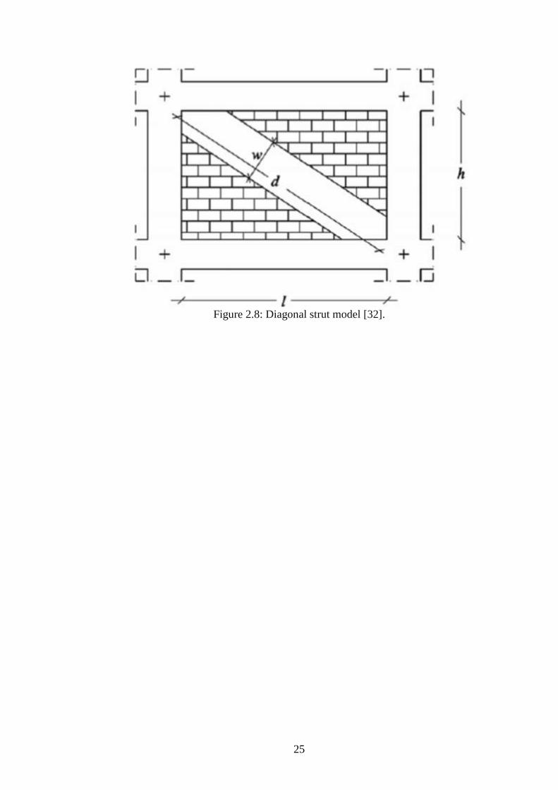
3.6 Experimental set-up
A self-equilibrating test set-up, as illustrated in Figs. 3.5 and 3.6, were used to test
moment frame without and with masonry infilled wall. These frames were subjected
to lateral loading applied at the frame’s beam to column connection level. The
hydraulic jack loading arrangement was supported off the reinforced concrete 1250
mm thick reaction wall. The moment frame specimens with and without infill wall
were made up of HE120B steel column and IPE120 steel beam and then via the
columns base plates they were connected to the steel supports which were also
connected to 1400 mm thick reinforced concrete strong floor. Lateral load was
applied by a hydraulic jack (1000 kN capacity) to the mid height of the top beam,
IPE 120 beam, and it was measured by a load cell having a capacity of (1000 kN).
32
Figure 3.5: Test frame set-up for major and minor axis (without infill wall).
Figure 3.6: Test frame set-up for major and minor axis (with infill wall).
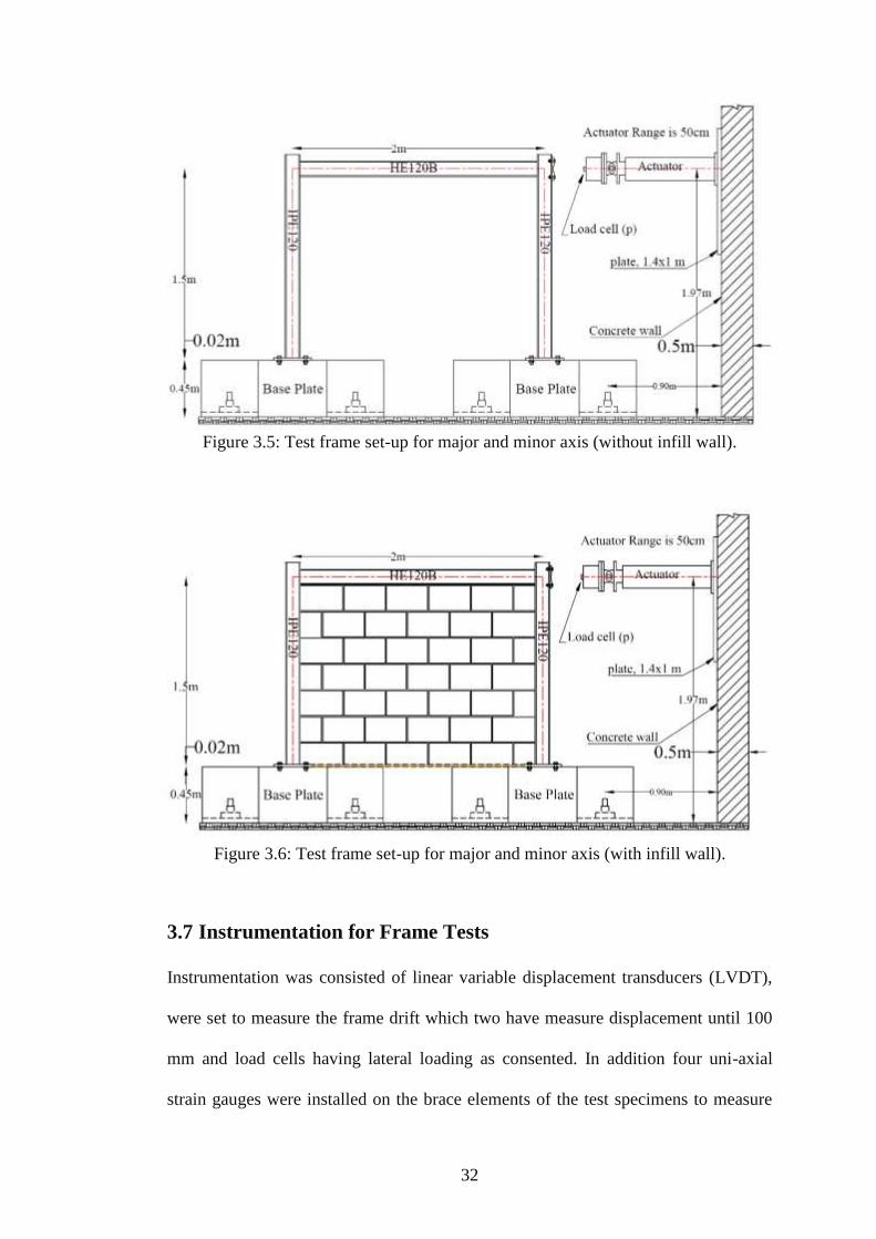
3.7 Instrumentation for Frame Tests
Instrumentation was consisted of linear variable displacement transducers (LVDT),
were set to measure the frame drift which two have measure displacement until 100
mm and load cells having lateral loading as consented. In addition four uni-axial
strain gauges were installed on the brace elements of the test specimens to measure
33
strains parallel to the main axes of the braces (SG1 to SG4 in Figs. 3.7 and 3.8). The
strain gauges on brace elements can measure both axial and out-of-plane bending
strains.
The lateral loading system made it possible to apply loads proportional to top of
beam level. Attachment detail of LVDTs’ and cell lateral loads’ on steel frames were
used with and without infill walls is shown in Figures 3.5, 3.6, 3.7 and 3.8.
Figure 3.7: Locations of LVDTs and Load the major or minor axis for Moment
Frame without infill wall (MAJ-MF5, MIN-MF1).

34
Figure 3.8: Locations of LVDTs and Load the major or minor axis for Moment
Frame with infill wall (MAJ-MFIN6, MIN-MFIN2).
Figure 3.9: Locations of LVDTs and Load Cell on the major or minor axis for
Braced Frame (MAJ-BF7, MIN-BR3).

35
Figure 3.10: Locations of LVDTs and Load Cell on the major or minor axis for
Braced Frame infill wall (MAJ-BFIN8, MIN-BRIN4).
3.8 Test Procedure
Firstly, the specimen was positioned in the test frame before any test was conducted
and it was aligned properly for both in-plane and out of plane direction. LVDTs were
placed at their specified areas and all readings were checked to make sure that they
functioned properly before the test began. Lateral load was applied constantly at
approximately a rate of 5 kN per minute up to the point where the specimen
fractured. The failure was expected to happen when the specimen showed a
permanent decline in the load. Load cell and LVDT readings were observed and
recorded with an interval of 0.1 s overall for each test using an electronic data
acquisition system. Amid each test, displacement, the crack pattern corresponding to
the, ultimate load were recorded.

36
3.9 Connection Design of Test Frames
In this part, two types of semi-rigid connections were used. These two types of
connections are stiffened extended end plate and stiffened fin plate connections.
They are used for moment and braced frames, respectively. The connection was
designed as Simple connections are clear in section (i) to (v). The connection design
are carried out according to British Steel Design Code BS 5950-2000.
i. Pinned Connections for Moment Frame (major axis)
Distinctive flexible end plate connections are shown in figure 3.11 (a). These are
assumed to transmit end shear only and to have ineffective resistance to rotation.
Hence, they do not transfer substantial moments at the ultimate limit state. This
explanation underlies the design of multi-storey braced frames in Britain designed as
'simple construction' in which the beams are designed as simply-supported and the
columns are designed for axial load and the small moments induced by the end
reactions from the beams [36].
ii. Flexible End Plate Connections for Moment Frame (minor axis)
Typical flexible end plate connections are shown in Figure 3.11 (b); it is assumed to
transmit end shear only and to have resistance to rotation. The end plate is welded to
the end of beam at the fabrication shop.

37
Figure 3.11: Geometric variables for major and minor axis of moment framed
connection
iii. Fin Plates Connection of Bracing Frame (major axis)
Typical Fin Plate Connections are shown in figure 3.12 (a). Fin plate connections
allow the use of minimum resources to fabricate and simple to erect lessening cost.
These connections are widely used because of their advantages of cost and ease to
erect. A fin plate connection is simply connection include, Beam-to-beam and beam-
to-column connections.
A fin plate connection has a piece of plate welded during manufacturing to the
supporting member, and the supported beam web and bracing is bolted on site the
figure below illustrates.
iv. Fin Plates Connection of Bracing Frame (minor axis)
Typical fin plate connections are shown in Figure 3.12 (b). A fin plate connection is
simple connection and includes beam-to-beam and beam-to-column web
connections.

38
Bracing systems are assumed that all forces intersect on member centerlines to
overpass the effects of any significant eccentricity. However, realizing this
assumption during the connection design may result in a connection with a very large
gusset plate, as given in Fig. 3.12.
Figure 3.12: Geometric variables for major and minor axis braced framed
connections.
v. Column Bases
Column bases are shown in figures 3.13 and 3.14. They comprised of one plate fillet
welded to the end of the column and connected to very stiff steel bases via four bolts
that are in turn connected to 1.4 m thick strong floor.
Bracing arrangements may involve the bracing members working in tension alone,
or in both tension and compression. The bracing member is connected by bolting to a
gusset plate, which is welded to the column, and to the base plate as shown in the
Figure 3.12.

39
Figure 3.13: Moment frame column base plate design for major-minor (all dimension
are mm).

40
Figure 3.14: Braced Frame column base plate design for major-minor axis (all
dimension are mm).
3.9.1 Structural Bolts
In this section, the background of standard hexagonal bolts is presented (Fig. 3.13).
Bolt grade of 10.9 was used and the strength of the structural bolts was as per the
British standards, BS 5950-2000. In this case study specifies requirements to used
M12, M16, and M20 as shown in figure 3.12. To determine the length of bolts, one
can follow Table 3.2, as per DIN 7990.

41
Figure 3.15: Hexagon head structural bolts used in experimental tests.
Table 3.4: Bolt and nut dimensions [5] (all dimenstion are mm).
42
Chapter 4
4. EXPERIMENTAL RESULTS AND DISCUSSIONS
4.1 Introduction
Included in this chapter are the results of eight half scale steel framed tests with and
without infill walls. The test set up details are given in chapter 3 where all the
locations of LVDTs that were used for measuring displacements and the locations for
strain gauges that were used to eventually calculate the axial forces in the cross
bracings are given. The readings taken from these LVDTs, strain gauges and the load
cell were used to produce the tables and graphs given in this chapter. The main aim
was to understand the behavioral changes between steel moment framed and braced
framed structures and the effect of infilling them with walls.
Steel beam was connected to steel columns either via the column flange (major axis)
or column web (minor axis). So the eight tests were divided as moment or braced
frame with minor or major axis and with or without infill walls. This created the
eight specimens which were identified by the following test numbers: MIN-MF1,
MIN-MFIN2, MIN-BR3, MIN-BRIN4, MAJ-MF5, MAJ-MFIN6, MAJ-BF7 and
MAJ-BFIN8 (Table 4.1). Two base supports, 1000 mm long 450 mm wide and 500
mm high were used to securely connect the column base plates. There was a
cumulative horizontal load applied at the top right hand corner of the beam. Lateral
load was applied gradually at an approximate rate of 5 to 8 kN per second until the
failure of the specimen. The failure was considered to have occurred when the

43
applied load was noticed to have an irreversible decrease. Also, the magnitudes of
displacements at the top left corner (LVDT2) of the panel were recorded.
Table 4.1: Key for the steel frame test numbers.
Test No. AxisFraming
Method
With/Without
Infill Wall
MIN-MF1 Minor Moment
MIN-MF-IN2 Minor Moment Infill Wall
MIN-BR3 Minor Braced
MIN-BRIN4 Minor Braced Infill Wall
MAJ-MF5 Major Moment
MAJ-MF-IN6 Major Moment Infill Wall
MAJ-BF7 Major Braced
MAJ-BFIN8 Major Braced Infill Wall
4.2 Mechanical Properties of Steel Sections Used for Test Frames
Tensile tests provided mechanical properties of the steel sections, beams, columns
and equal leg angles, used for the tests (Table 4.2). Three specimen were taken from
the flanges and web of the beam (FL1, FL2, WE3) flanges and web of the column
(FL3, FL4, WE5) and two legs of the angle (L1, L2). The specimens had higher yield
stresses ranging from 306.5 MPa to 399.3 MPa than the nominal yield stress of 275
MPa. The ultimate stress of the specimens was approximately ranging from 462.1 to
590.8 MPa which was within the range of the nominal stress of 340 MPa to 560
MPa. The actual dimensions of these steel sections are given in Table 4.3.

44
Table 4.2: Mechanical properties of the tested steel sections.
Thickness with Lo Lf Area
(mm) (mm) (mm) (mm) (mm2) (N/mm
2) (N/mm
2) %
FL1 9.47 25.00 200.00 258.00 236.75 312.60 466.70 29.00
FL2 9.47 25.00 200.00 257.00 236.75 321.00 466.70 28.50
WE3 6.60 25.00 200.00 245.00 165.00 385.50 490.90 22.50
FL3 5.35 25.00 200.00 245.00 133.75 306.50 462.10 22.50
FL4 5.35 25.00 200.00 240.00 133.75 306.50 462.10 20.00
WE5 3.56 25.00 200.00 249.00 89.00 343.80 516.90 24.50
L1 5.85 25.00 200.00 240.00 146.25 396.60 582.60 20.00
L2 5.85 25.00 200.00 244.00 146.25 399.30 590.80 22.00
Coupon dimension of sample testing Yield
stress
Ultimate
stress
Ultimate
strain
HEB120
Steel section Sample No.
IPE120
L60X6

45
Table 4.3: Sections properties used in the test frame
Flange Web Height Width Flange Web Height Width Leg Leg Leg
Thick Thick Thick Thick Thick Lengt
(tf) (tw) (hc) (bc) (tf) (tw) (hc) (bc) (ta) (L1) (L2)
MIN-MF1 10.0 7.0 122 121 6.4 6.5 120 64 60 60
MIN-MFIN2 10.0 6.5 122 121 6.4 6.5 120 64 60 60
MIN-BR3 10.5 7.0 122 121 7.0 6.5 118 64 6 60 60
MIN-BRIN4 10.0 6.5 122 121 6.5 6.5 118 64 6 60 60
MAJ-MF5 10.0 6.5 123 121 7.0 5.6 120 64 60 60
MAJ-MFIN6 10.0 6.5 122 121 7.0 5.5 120 64 60 60
MAJ-BF7 10.0 6.5 122 121 7.0 5.0 119 64 6 60 60
MAJ-BFIN8 10.0 6.5 120 121 7.0 5.5 120 64 6 60 60
Test No
HEB120 (mm) IPE (mm) L 60x60x6 (mm)
4.3 Minor Axis Frame Tests
In this test the beam two ends were connected to column webs, therefore, during the
tests columns were subjected to bending mainly around their minor axis (Fig. 4.1).
Figure 4.1: Minor axis frame and load direction for HE120B column section.
46
4.3.1 Moment Frame without Infill Wall (MIN-MF1)
The test setup consisted of lateral load applied by using a hydraulic jack with a
capacity of 1000 kN. The test set up including the locations of LVDTs and the
hydraulic jack are given in Figure 3.5 and the readings taken from these measuring
devices are given in Table 4.4. It shows the results of LVDT and rotation testing for
(MIN-MF1) under loading applied gradually.

47
Table 4.4: Displacements and rotations measured at various locations for the
moment frame without infill wall (MIN-MF1).
Lateral Load Drift ratio Rotation
P LVDT1 LVDT2 (α) (ø)
(kN) (mm) (mm) (%) (radians)
0.00 0.00 0.00 0.00 0.00
1.33 0.11 0.94 0.02 1.10
4.83 0.70 2.17 0.15 1.95
6.00 0.95 2.91 0.19 2.62
9.66 1.63 4.43 0.30 3.73
12.83 2.30 6.10 0.41 5.07
15.00 2.64 6.87 0.46 5.65
18.00 3.23 8.31 0.55 6.77
20.83 3.83 9.74 0.65 7.88
22.00 4.00 10.15 0.68 8.19
25.00 4.58 11.48 0.77 9.20
27.84 5.16 12.87 0.86 10.27
30.84 5.77 14.24 0.95 11.29
32.34 6.17 15.25 1.02 12.11
34.67 6.69 16.56 1.10 13.15
38.67 7.58 18.39 1.23 14.41
40.01 7.95 19.21 1.28 15.01
42.51 8.69 20.85 1.39 16.21
45.01 9.30 22.04 1.47 16.99
47.17 10.05 23.73 1.58 18.24
50.01 11.29 26.52 1.77 20.30
52.51 12.68 29.49 1.97 22.41
55.01 14.50 33.25 2.22 24.99
57.51 16.80 37.83 2.52 28.04
60.01 19.85 43.90 2.93 32.07
62.51 24.50 53.23 3.55 38.31
65.01 31.35 67.77 4.52 48.57
66.01 35.69 77.29 5.15 55.46
67.01 40.00 86.83 5.79 62.43
67.51 41.48 90.09 6.01 64.81
66.68 41.63 90.39 6.03 65.01
Displacement (∆)
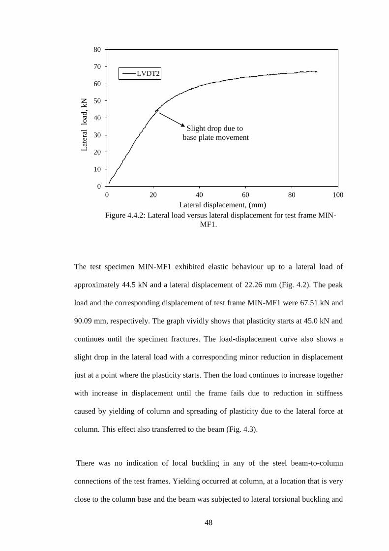
48
Figure 4.4.2: Lateral load versus lateral displacement for test frame MIN-
MF1.
The test specimen MIN-MF1 exhibited elastic behaviour up to a lateral load of
approximately 44.5 kN and a lateral displacement of 22.26 mm (Fig. 4.2). The peak
load and the corresponding displacement of test frame MIN-MF1 were 67.51 kN and
90.09 mm, respectively. The graph vividly shows that plasticity starts at 45.0 kN and
continues until the specimen fractures. The load-displacement curve also shows a
slight drop in the lateral load with a corresponding minor reduction in displacement
just at a point where the plasticity starts. Then the load continues to increase together
with increase in displacement until the frame fails due to reduction in stiffness
caused by yielding of column and spreading of plasticity due to the lateral force at
column. This effect also transferred to the beam (Fig. 4.3).
There was no indication of local buckling in any of the steel beam-to-column
connections of the test frames. Yielding occurred at column, at a location that is very
close to the column base and the beam was subjected to lateral torsional buckling and
0
10
20
30
40
50
60
70
80
0 20 40 60 80 100
Lat
eral
lo
ad, kN
Lateral displacement, (mm)
Slight drop due to
base plate movement
LVDT2
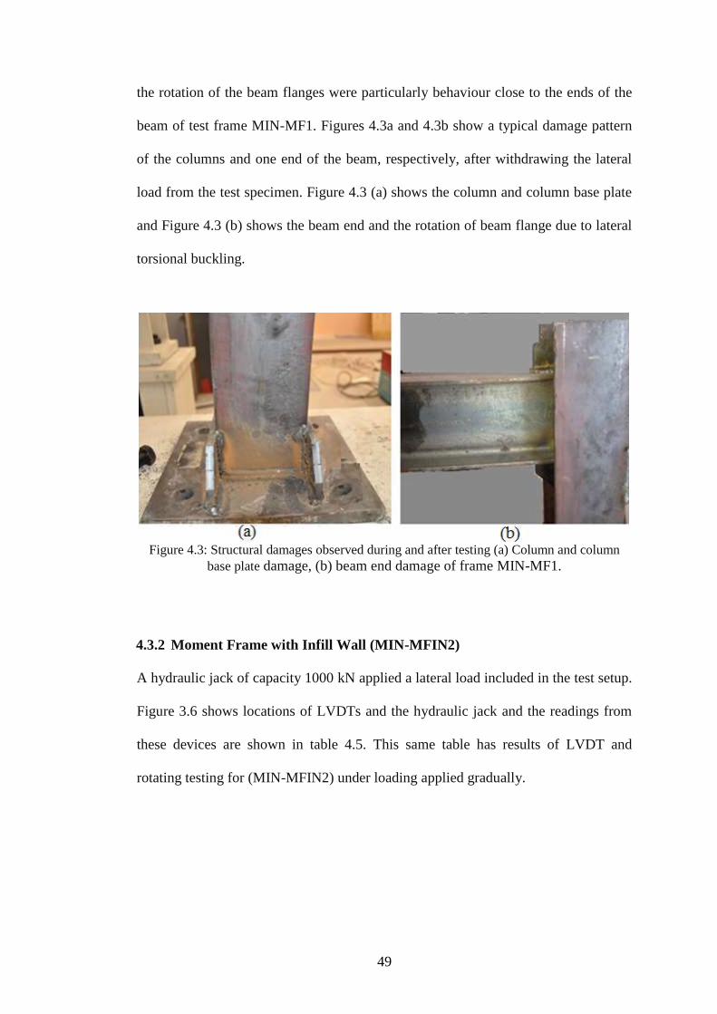
49
the rotation of the beam flanges were particularly behaviour close to the ends of the
beam of test frame MIN-MF1. Figures 4.3a and 4.3b show a typical damage pattern
of the columns and one end of the beam, respectively, after withdrawing the lateral
load from the test specimen. Figure 4.3 (a) shows the column and column base plate
and Figure 4.3 (b) shows the beam end and the rotation of beam flange due to lateral
torsional buckling.
Figure 4.3: Structural damages observed during and after testing (a) Column and column
base plate damage, (b) beam end damage of frame MIN-MF1.
4.3.2 Moment Frame with Infill Wall (MIN-MFIN2)
A hydraulic jack of capacity 1000 kN applied a lateral load included in the test setup.
Figure 3.6 shows locations of LVDTs and the hydraulic jack and the readings from
these devices are shown in table 4.5. This same table has results of LVDT and
rotating testing for (MIN-MFIN2) under loading applied gradually.
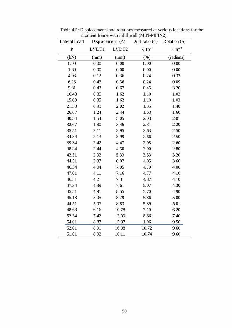
50
Table 4.5: Displacements and rotations measured at various locations for the
moment frame with infill wall (MIN-MFIN2).
Lateral Load Drift ratio (α) Rotation (ѳ)
P LVDT1 LVDT2 × 10-3
× 10-3
(kN) (mm) (mm) (%) (radians)
0.00 0.00 0.00 0.00 0.00
1.60 0.00 0.00 0.00 0.00
4.93 0.12 0.36 0.24 0.32
6.23 0.43 0.36 0.24 0.09
9.81 0.43 0.67 0.45 3.20
16.43 0.85 1.62 1.10 1.03
15.00 0.85 1.62 1.10 1.03
21.30 0.99 2.02 1.35 1.40
26.67 1.24 2.44 1.63 1.60
30.34 1.54 3.05 2.03 2.01
32.67 1.80 3.46 2.31 2.20
35.51 2.11 3.95 2.63 2.50
34.84 2.13 3.99 2.66 2.50
39.34 2.42 4.47 2.98 2.60
38.34 2.44 4.50 3.00 2.80
42.51 2.92 5.33 3.53 3.20
44.51 3.37 6.07 4.05 3.60
46.34 4.04 7.05 4.70 4.00
47.01 4.11 7.16 4.77 4.10
46.51 4.21 7.31 4.87 4.10
47.34 4.39 7.61 5.07 4.30
45.51 4.91 8.55 5.70 4.90
45.18 5.05 8.79 5.86 5.00
44.51 5.07 8.83 5.89 5.01
48.68 6.16 10.78 7.19 6.20
52.34 7.42 12.99 8.66 7.40
54.01 8.87 15.97 1.06 9.50
52.01 8.91 16.08 10.72 9.60
51.01 8.92 16.11 10.74 9.60
Displacement (∆)

51
Fig. 4.4: Lateral load versus lateral displacement for test frame MIN-MFIN2.
The test specimen MIN-MFIN2 exhibited elastic behavior up to approximately 42.5
kN lateral load, which corresponds to a lateral displacement at the top of frame 5.33
mm. The first visible crack was noticed at a lateral load of approximately 47 kN and
a lateral displacement of 7.16mm. Figure 4.4 shows the distribution of the data on the
curve is inconsistent but there was no visible unevenness of the beam. The pattern of
diagonal cracks were in such a way that a single diagonal crack occurred at the end
of first ten loading steps, which corresponds to approximately 15 kN (Fig. 4.5). By
increase the load, the first crack developed into another diagonal crack and few
shorter branching off these main diagonal cracks, as can be seen in Fig. 4.5 (b). Two
diagonal hairline cracks were started to form at the top compression corner of the
infill panel at approximately 45°. This means that diagonal compression strut
mechanism was fully developed as shown in Fig. 4.5 (b). This approach applies to
the mansory infilled frame as a braced frame replaced by mansory infill to resist the
lateral loading equivalent diagonal strut acting in compression [29].
0
10
20
30
40
50
60
0 2.5 5 7.5 10 12.5 15 17.5
Lat
eral
lo
ad (
kN
)
Lateral displacement (mm)
First visible
crack on the wall
LVDT2

52
The peak lateral load applied to the MIN-MFIN2 specimen was 54.01 kN and
15.97mm lateral displacement was achieved. At this point, cracks of infill wall were
diagonal cracks and there was no crushing at the top left and top right corners of the
panel.
Figure 4.5: Diagonal cracks of the infill wall at the location of a compression
diagonal bracing for test frame MIN-MFIN2.
4.3.3 Braced Frame without Infill Wall (MIN-BR3)
A 1000 kN capacity hydraulic jack applies lateral load to the test setup. In this test
setup, locations of LVDTs and hydraulic jack are given in Figure 3.7. The readings
recorded from these measuring devices are displayed in Table 4.6. It displays the
results of LVDT and rotating testing for (MIN-BR3) under gradually applied load.

53
Table 4.6: Displacements and rotations measured at various locations for the
braced frame without infill wall (MIN-BR3).
Lateral Load Drift ratio (α) Rotation (ѳ)
P LVDT1 LVDT2 × 10-3
× 10-3
(kN) (mm) (mm) (%) (radians)
0.00 0.00 0.00 0.00 0.00
7.50 0.11 0.01 0.07 -0.01
10.84 0.30 0.01 0.07 -0.04
15.84 0.51 0.50 3.33 0.00
22.50 0.74 0.98 6.53 0.03
25.67 0.86 1.32 8.80 0.06
30.84 1.13 1.85 12.33 0.10
35.01 1.24 2.13 14.20 0.12
40.01 1.43 2.62 17.47 0.16
45.18 1.63 3.11 20.73 0.19
50.34 1.85 3.63 24.20 0.24
55.18 2.02 4.08 27.20 0.28
60.18 2.24 4.64 30.93 0.32
65.35 2.37 4.99 33.27 0.35
70.35 2.52 5.36 35.73 0.38
75.18 2.65 5.73 38.20 0.41
80.01 2.77 6.02 40.13 0.43
85.18 2.91 6.41 42.73 0.47
90.18 3.09 6.88 45.87 0.51
95.35 3.31 7.41 49.40 0.55
100.35 3.37 7.54 50.27 0.56
105.35 3.59 8.13 54.20 0.61
110.19 3.96 9.20 61.33 0.69
114.02 4.29 10.14 67.60 0.78
113.36 4.55 10.96 73.07 0.86
113.02 4.78 11.66 77.73 0.92
98.69 4.68 11.50 76.67 0.91
104.69 4.82 11.79 78.60 0.93
110.02 5.30 13.15 87.67 1.05
115.52 5.86 14.71 98.07 1.18
120.02 6.26 15.86 105.73 1.28
125.36 6.71 17.13 114.20 1.39
130.03 7.21 18.55 123.67 1.51
135.03 7.80 20.20 134.67 1.65
138.03 8.61 22.46 149.73 1.85
137.36 8.68 22.63 150.87 1.86
135.86 8.73 22.74 151.60 1.87
Displacement (∆)
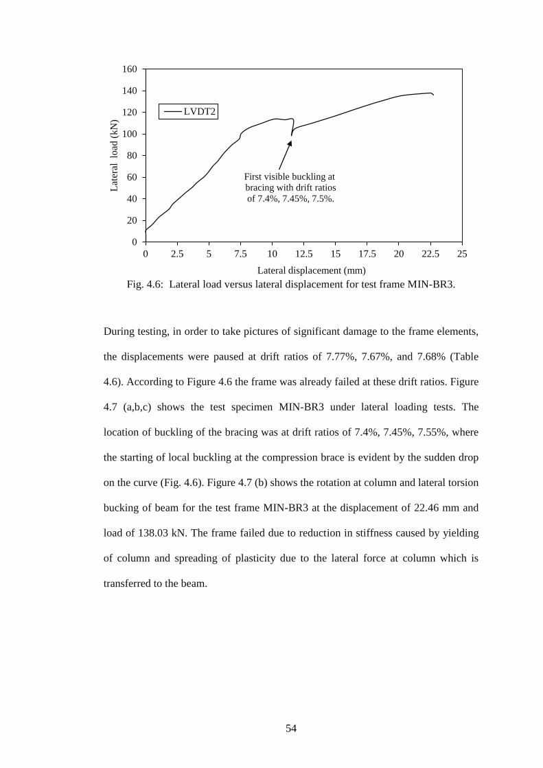
54
Fig. 4.6: Lateral load versus lateral displacement for test frame MIN-BR3.
During testing, in order to take pictures of significant damage to the frame elements,
the displacements were paused at drift ratios of 7.77%, 7.67%, and 7.68% (Table
4.6). According to Figure 4.6 the frame was already failed at these drift ratios. Figure
4.7 (a,b,c) shows the test specimen MIN-BR3 under lateral loading tests. The
location of buckling of the bracing was at drift ratios of 7.4%, 7.45%, 7.55%, where
the starting of local buckling at the compression brace is evident by the sudden drop
on the curve (Fig. 4.6). Figure 4.7 (b) shows the rotation at column and lateral torsion
bucking of beam for the test frame MIN-BR3 at the displacement of 22.46 mm and
load of 138.03 kN. The frame failed due to reduction in stiffness caused by yielding
of column and spreading of plasticity due to the lateral force at column which is
transferred to the beam.
0
20
40
60
80
100
120
140
160
0 2.5 5 7.5 10 12.5 15 17.5 20 22.5 25
Lat
eral
lo
ad (
kN
)
Lateral displacement (mm)
First visible buckling at
bracing with drift ratios
of 7.4%, 7.45%, 7.5%.
LVDT2

55
Figure 4.7: Test specimen MIN-BR3 under lateral loading (a) out-of-plane bending
and local buckling of the compressive member of the cross-bracing, (b) out-of-plane
bending of beam and (c) torsion of column and bucking at bracing.
4.3.4 Braced Frame with Infill Wall (MIN-BRIN4)
Lateral load was applied by a hydraulic jack with 1000KN capacity to the test setup.
Figure 3.8 has locations of the LVDTs and the hydraulic jack. Readings from these
measuring devices are shown in table 4.7. Rotation testing for (MIN-BRIN4) under
gradual loading and LVDT results are shown in table 4.7.

56
Table 4.7: Displacements and rotations measured at various locations for the
braced frame with infill wall MIN-BRIN4.
Lateral Load Drift ratio (α) Rotation (ѳ)
P LVDT1 LVDT2 × 10-2
× 10-2
KN (mm) (mm) % radians
0.00 0.00 0.00 0.00 0.00
1.17 0.02 0.01 0.67 0.00
8.67 0.07 0.09 0.60 0.00
15.67 0.14 0.20 13.33 0.08
22.50 0.23 0.34 22.67 0.15
27.67 0.32 0.49 32.67 0.23
33.01 0.44 0.70 46.67 0.35
37.34 0.63 1.02 68.00 0.53
40.01 0.73 1.22 81.33 0.66
45.34 0.87 1.50 100.00 0.84
50.51 1.03 1.82 121.33 1.06
55.34 1.15 2.07 138.00 1.23
60.18 1.29 2.39 159.33 1.47
65.01 1.42 2.64 176.00 1.63
70.51 1.56 2.93 195.33 1.83
75.68 1.72 3.23 215.33 2.01
80.18 1.88 3.53 235.33 2.21
85.68 2.12 3.98 265.33 2.49
90.18 2.27 4.28 285.33 2.68
95.52 2.54 4.79 319.33 3.01
110.36 3.21 6.11 407.33 3.87
117.52 3.63 7.03 468.67 4.53
125.19 4.04 7.86 524.00 5.10
135.19 4.71 9.26 617.33 6.10
140.19 5.20 10.33 688.67 6.84
150.53 5.85 11.73 782.00 7.84
160.53 6.31 12.74 849.33 8.57
170.53 6.92 14.17 944.67 9.67
180.20 7.38 15.15 1000.00 10.37
187.70 7.84 15.98 1065.33 10.85
193.04 8.23 16.66 1110.67 11.24
199.04 8.52 17.27 1151.33 11.67
197.87 8.62 17.51 1167.33 11.85
199.87 8.71 17.68 1178.67 11.97
195.87 8.99 18.43 1228.67 12.59
193.54 9.13 18.81 1254.00 12.91
190.54 9.29 19.34 1289.33 13.40
Displacement (∆)
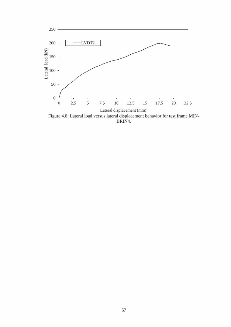
57
Figure 4.8: Lateral load versus lateral displacement behavior for test frame MIN-
BRIN4.
0
50
100
150
200
250
0 2.5 5 7.5 10 12.5 15 17.5 20 22.5
Lat
eral
lo
ad (
kN
)
Lateral displacement (mm)
LVDT2
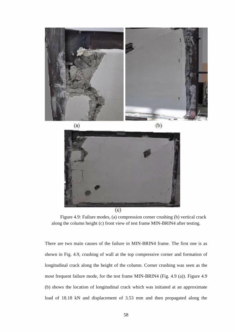
58
Figure 4.9: Failure modes, (a) compression corner crushing (b) vertical crack
along the column height (c) front view of test frame MIN-BRIN4 after testing.
There are two main causes of the failure in MIN-BRIN4 frame. The first one is as
shown in Fig. 4.9, crushing of wall at the top compressive corner and formation of
longitudinal crack along the height of the column. Corner crushing was seen as the
most frequent failure mode, for the test frame MIN-BRIN4 (Fig. 4.9 (a)). Figure 4.9
(b) shows the location of longitudinal crack which was initiated at an approximate
load of 18.18 kN and displacement of 3.53 mm and then propagated along the

59
column height. Second cause of failur, buckling of the bracing angle due to
compressive load and this was observed as a sudden drop on the lateral load-
displacement curve at around 199.87 kN lateral load with a corresponding
displacement of about 17.5 mm (Fig. 4.8). Figure 4.8 shows the data obtained from
the load cell and LVDT 2 as lateral load versus displacement, respectively. The
elastic region stretches up to a lateral load of approximately 135.19 kN and lateral
displacement of 9.26 mm.
4.4 Major Axis Frame Tests
In this test the beam ends were connected to column flanges, therefore, during the
tests columns were subject to bending mainly around their major axis (Figure 4.10).
Figure 4.10: Major axis frame and load direction for HE120B column section

60
4.4.1 Moment Frame without Infill Wall (MAJ-MF5)
The test setup consisted of lateral load from a 1000KN capacity hydraulic jack. In
figure 3.5, location of the LVDTs and hydraulic jack are given and readings obtained
are shown in table 4.8. Table 4.8 shows rotation testing for (MAJ-MF5) under
gradual loading and LVDT results.
Table 4.8: Displacements and rotations measured at various locations for the
moment frame without infill wall (MAJ-MF5).
Lateral Load Drift ratio (α) Rotation (ѳ)
P LVDT1 LVDT2 × 10-3
kN (mm) (mm) % radians
0.00 0.00 0.00 0.00 0.00
1.33 0.20 0.45 0.03 0.34
5.00 0.58 1.32 0.09 0.99
10.17 1.16 2.64 0.18 2.00
16.17 1.70 3.70 0.25 2.67
20.00 2.18 4.75 0.32 3.43
26.01 2.99 6.48 0.43 4.65
30.84 3.69 8.06 0.54 5.83
35.67 4.38 9.47 0.63 6.79
40.01 5.06 10.97 0.73 7.89
45.01 5.82 12.60 0.84 9.04
50.01 6.56 14.18 0.95 10.16
55.18 7.35 15.88 1.06 11.37
60.18 8.02 17.32 1.15 12.40
65.01 8.82 19.07 1.27 13.67
70.18 9.74 21.12 1.41 15.17
75.01 10.68 23.28 1.55 16.81
80.18 11.89 26.11 1.74 18.97
85.01 13.18 29.07 1.94 21.19
90.35 14.96 33.13 2.21 24.23
95.02 16.77 37.08 2.47 27.10
100.19 19.40 42.81 2.85 31.21
105.69 31.57 69.30 4.62 50.31
104.19 31.70 69.61 4.64 50.55
102.85 31.77 69.65 4.64 50.51
Displacement (∆)

61
Fig. 4.11: Lateral load versus lateral displacement for test frame MAJ-MF5.
The test specimen MAJ-MF5 exhibited elastic behaviour up to a lateral load of
approximately 60.18 kN and a lateral displacement of 17.32 mm (Fig. 4.11). The
peak load and the corresponding displacement of test frame MAJ-MF5 were 105.69
kN and 69.3 mm, respectively. The graph vividly shows that plasticity starts at 60.18
kN up until the specimen fractures.
There was indication of lateral torsional buckling along the steel beam (Fig. 4.12 a)
also there was bending at base plate (Fig. 4.12 b) but there was no damage in any of
the steel beam-to-column connections of test frame MAJ-MF5. Yielding occurred at
beam ends, at locations that are very close to the beam-to-column connections.
0
20
40
60
80
100
120
0 10 20 30 40 50 60 70
Lat
eral
lo
ad (
kN
)
Lateral displacement (mm)
LVDT2
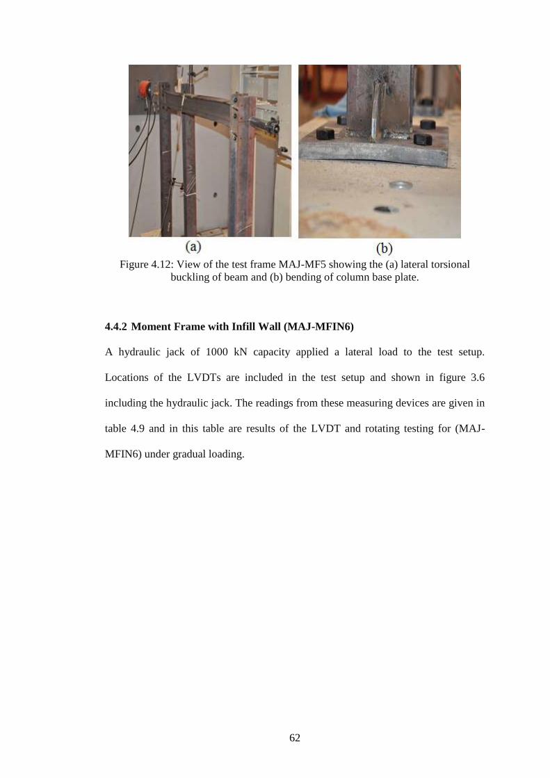
62
Figure 4.12: View of the test frame MAJ-MF5 showing the (a) lateral torsional
buckling of beam and (b) bending of column base plate.
4.4.2 Moment Frame with Infill Wall (MAJ-MFIN6)
A hydraulic jack of 1000 kN capacity applied a lateral load to the test setup.
Locations of the LVDTs are included in the test setup and shown in figure 3.6
including the hydraulic jack. The readings from these measuring devices are given in
table 4.9 and in this table are results of the LVDT and rotating testing for (MAJ-
MFIN6) under gradual loading.

63
Table 4.9: Displacements and rotations measured at various locations for the
moment frame with infill wall (MAJ-MFIN6).
Lateral Load Drift ratio (α) Rotation (ѳ)
P LVDT1 LVDT2 × 10-2
× 10-3
kN (mm) (mm) % radians
0.00 0.00 0.00 0.00 0.00
2.33 0.07 0.00 0.00 -0.09
9.17 0.39 0.00 0.00 -0.51
11.84 0.51 0.16 1.17 -0.47
14.67 0.95 1.13 7.53 0.25
20.34 1.33 1.97 13.13 0.85
25.51 1.64 2.64 17.60 1.33
30.51 2.04 3.52 23.47 1.98
35.17 2.30 4.02 26.80 2.29
40.17 2.58 4.58 30.53 2.67
45.01 3.02 5.43 36.20 3.22
50.18 3.55 6.37 42.47 3.76
54.01 4.02 7.01 46.73 3.99
53.34 4.04 7.06 47.07 4.03
55.51 4.31 7.61 50.73 4.40
58.85 4.62 8.10 54.00 4.65
57.18 4.99 8.49 56.60 4.67
57.84 6.36 10.85 72.33 5.99
59.01 7.05 12.15 81.00 6.81
62.35 7.92 13.89 92.60 7.97
65.68 8.32 14.69 97.93 8.49
67.51 8.66 15.40 102.67 8.99
70.01 8.96 16.09 107.27 9.51
69.85 9.03 16.26 108.40 9.64
75.01 9.54 17.48 116.53 10.59
77.52 10.15 18.82 125.47 11.57
80.18 10.47 19.62 130.80 12.20
85.18 11.07 20.96 139.73 13.19
90.02 13.30 25.97 173.13 16.90
95.02 14.23 27.95 186.33 18.29
93.52 14.27 28.02 186.80 18.33
92.52 14.27 28.00 186.67 18.31
95.85 14.40 28.31 188.73 18.55
100.02 14.88 29.39 195.93 19.35
103.69 15.87 31.83 212.20 21.29
101.69 15.96 32.10 214.00 21.52
99.19 16.01 32.17 214.47 21.55
Displacement (∆)

64
Fig. 4.13 Lateral load versus lateral displacement for test frame MAJ-MFIN6.
The test specimen MAJ-MFIN6 presented elastic behaviour up to approximately
57.18 kN and its corresponding displacement of 8.49 mm. Steel yielding occurred
first in the column, and followed by the yielding of the column and beam. This
behaviour can mainly be attributed to the interaction between the infill wall and the
surrounding frame (Fig. 4.14 (a, b and c)). Figure 4.14 (a) and (b) shows the
formation of diagonal cracking followed by the compressive corner wall crushing.
The test frame stopped resisting the lateral load approximaitly at 103.69 kN with a
corresponding displacement of 31.83 mm. The corner crushing for this test frame
was observed well after the achievement of the ultimate load. While the diagonal
cracking was like a behaviour bracing and the corner crushing was a type of
compression failure of the diagonal bracing. This method treats the masonry infilled
frame as a braced frame with the masonry infill replaced by an to resist the lateral
loading equivalent diagonal strut acting in compression [30].
0
20
40
60
80
100
120
0 5 10 15 20 25 30 35
Lat
eral
lo
ad (K
N)
lateral displacement (mm)
Second visible diagonal
crack at 57.18 kN
LVDT2

65
Figure 4.14: (a) Formation of the diagonal cracks followed by (b) compressive corner
crushing of the infill wall and (b) damage due to infill wall-steel frame interaction for
test frame MIN-MFIN6.
4.4.3 Braced Frame without Infill Wall (MAJ-BF7)
Lateral load was applied in the test setup by a hydraulic jack of 1000KN capacity.
Figure 3.7 shows LVDTs locations and the hydraulic jack as well as readings from
these measuring devices are given in Table 4.10. The results of LVDTs and rotation
testing (MAJ-BF7) under gradually applied loading are shown in Table 4.10.

66
Table 4.10: Displacements and rotations measured at various locations for the
braced frame without infill wall (MAJ-BF7).
Lateral Load Drift ratio (α) Rotation (ѳ)
P LVDT1 LVDT2 × 10-2
× 10-3
kN (mm) (mm) % radians
0.00 0.00 0.00 0.00 0.00
3.17 0.07 0.25 1.67 0.25
8.84 0.24 0.66 4.40 0.57
15.34 0.46 1.18 7.87 0.96
21.84 0.71 1.86 12.40 1.53
28.84 1.15 3.18 21.20 2.71
34.34 1.31 3.49 23.27 2.91
40.17 1.58 4.22 28.13 3.53
45.84 1.78 4.81 32.07 4.05
50.34 1.92 5.16 34.40 4.33
55.18 2.04 5.52 36.80 4.64
60.35 2.17 5.84 38.93 4.89
70.18 2.39 6.38 42.53 5.33
75.85 2.50 6.63 44.20 5.51
80.18 2.57 6.79 45.27 5.63
85.68 2.64 6.95 46.33 5.75
91.02 2.76 7.14 47.60 5.85
97.02 2.84 7.36 49.07 6.03
91.18 2.69 6.92 46.13 5.65
118.52 3.04 7.48 49.87 5.93
125.19 3.08 7.60 50.67 6.03
130.86 3.14 7.78 51.87 6.19
135.53 3.21 7.96 53.07 6.34
140.36 3.27 8.10 54.00 6.45
145.69 3.32 8.18 54.53 6.49
150.03 3.36 8.26 55.07 6.53
155.19 3.42 8.34 55.60 6.56
160.70 3.50 8.43 56.20 6.58
165.53 3.58 8.58 57.20 6.67
170.53 3.70 8.78 58.53 6.78
180.20 3.87 9.05 60.33 6.91
178.70 3.83 8.90 59.33 6.76
175.20 3.76 8.68 57.87 6.57
170.53 3.69 8.50 56.67 6.42
166.70 3.62 8.29 55.27 6.23
Displacement (∆)

67
Figure 4.15 Lateral load versus lateral displacement test frame MAJ-BF7.
Fig. 4.16 (a,b,c) shows the test frame MAJ-BF7 under lateral loading tests. During
the testing, in order to take some pictures of significant damage to the elements
frame and its individual members, the displacements were paused at lateral load of
180.20 kN (Table 4.10) that mean the frame was failure. Figure 4.16 (a and c) shows
the significant rotation of beam-to-column joints at a frame rotation of 6.91×10⁻³ rad
and the lateral torsional buckling of beam, particularly close to the beam to column
connection can be seen in Fig. 4.16 (b). The rotation of the beam-column joint was
the main cause of the displacement and sideways movement of the frame members.
0
50
100
150
200
0 2 4 6 8 10
Lat
eral
lo
ad (
KN
)
Lateral displacement (mm)
sideways movement
at the beam
LVDT2

68
Figure 4.16: Various views of the test frame MAJ-BR7 showing the (a) damage of
the lateral torsional buckling (b) damages at the beam-column connection (c)
damages to bracing, beam, connection and torsion of the column members.
4.4.4 Braced Frame with Infill Wall (MAJ-BFIN8)
A hydraulic jack applied a lateral load to the test setup. The test setup along with
locations of the LVDTs are shown in figure 3.7 as well as the hydraulic jack.
Readings in table 4.11 are from these measuring devices and this table has results of
LVDTs and rotating testing for (MAJ-BFIN8) under loading applied gradually.

69
Table 4.11: Displacements and rotations measured at various locations for the
braced frame with infill wall (MAJ-BFIN8).
Lateral Load Drift ratio (α) Rotation (ѳ)
P LVDT1 LVDT2 × 10-2
× 10-4
kN (mm) (mm) % radians
0.00 0.00 0.00 0.00 0.00
0.17 0.01 0.01 0.07 0.07
6.67 0.10 0.16 1.06 0.80
11.00 0.20 0.30 0.02 1.33
16.00 0.44 0.66 4.40 3.00
21.01 2.15 2.29 15.27 1.87
27.51 3.00 3.12 20.80 1.60
34.01 4.57 4.59 30.60 0.33
40.34 5.18 5.22 34.80 0.53
45.18 5.77 5.83 38.87 0.87
50.84 6.12 6.25 41.67 1.73
55.18 6.17 6.38 42.53 2.87
60.01 6.23 6.49 43.27 3.53
59.35 6.23 6.49 43.27 3.53
65.18 6.30 6.69 44.60 5.27
70.51 6.43 7.03 46.87 8.00
75.18 6.55 7.27 48.47 9.60
80.35 6.64 7.53 50.20 11.93
85.18 6.73 7.81 52.07 14.47
91.02 6.82 8.01 53.40 15.87
100.52 7.03 8.38 55.87 18.00
110.02 7.15 8.64 57.60 19.93
116.36 7.26 8.84 58.93 21.13
125.53 7.37 9.02 60.13 22.00
132.03 7.50 9.20 61.33 22.73
137.36 7.56 9.22 61.47 22.20
145.69 7.65 9.28 61.87 21.80
150.03 7.72 9.39 62.60 22.33
157.20 7.81 9.57 63.80 23.47
165.37 7.95 9.81 65.40 24.80
170.03 8.00 9.88 65.87 25.13
175.04 8.03 9.86 65.73 24.47
180.20 8.01 9.75 65.00 23.27
186.20 8.03 9.89 65.93 24.80
192.21 8.08 9.96 66.40 25.13
202.71 8.12 10.14 67.60 26.93
210.04 8.14 10.19 67.93 27.33
214.04 8.14 10.21 68.07 27.67
217.21 8.11 10.43 69.53 30.93
212.21 8.04 10.33 68.87 30.53
206.71 7.99 10.21 68.07 29.60
Displacement (∆)
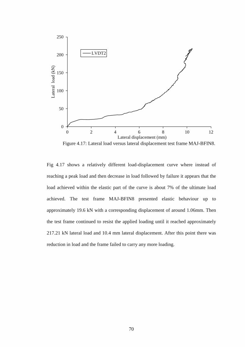
70
Figure 4.17: Lateral load versus lateral displacement test frame MAJ-BFIN8.
Fig 4.17 shows a relatively different load-displacement curve where instead of
reaching a peak load and then decrease in load followed by failure it appears that the
load achieved within the elastic part of the curve is about 7% of the ultimate load
achieved. The test frame MAJ-BFIN8 presented elastic behaviour up to
approximately 19.6 kN with a corresponding displacement of around 1.06mm. Then
the test frame continued to resist the applied loading until it reached approximately
217.21 kN lateral load and 10.4 mm lateral displacement. After this point there was
reduction in load and the frame failed to carry any more loading.
0
50
100
150
200
250
0 2 4 6 8 10 12
Lat
eral
lo
ad (
kN
)
Lateral displacement (mm)
LVDT2

71
Figure 4.18: Failure modes, (a) corner crushing due to compression (b) horizontal
crack along the beam length of test frame MAJ-BFIN8 after testing.
4.5 Discussion of Test Results
The most important aim of this study is to examine the significance of masonry infill
wall to the lateral strength and stiffness of moment and braced steel frame. The
analyses of experimental results were carried out step by step to figure out the effect
of various parameters on the behavior. These specifications are column orientation,
test frames with and without infill wall. The discussions on test results are given in
the following section.
4.5.1 Effect of Column Orientation on the Frame Action
Considering the frame to infill wall stiffness ratio results show that strong axis
orientation of the steel columns resulted in an increase in the ultimate load carrying
capacity of the test frame. Furthermore when the major axis test frame with infill
wall is compared with the one having column orientation in the weak axis, the
ultimate load capacity also higher.
4.5.1.1 Test Frames MAJ-MF5 and MIN-MF1
The effect of column orientation on the behaviour of test frame is further illustrated
in Fig 4.19. As anticipated, the test frame with major axis column orientation

72
exhibited markedly larger initial stiffness than those with minor axis column
orientation but the latter attained greater ultimate displacement and ultimate lateral
load, 20.79% and 38.18% higher, respectively. This indicates that the weaker test
frame with lower ultimate lateral load obtaining greater ductility than the stronger
test frame.
Figure 4.19: Comparison of load versus lateral displacement response for test
frame MAJ-MF5 and MIN-MF1 with different column axis orientation.
4.5.1.2 Test Frames MAJ-MFIN6 and MIN-MFIN2
The test frames with minor axis column orientation had developed diagonal cracks
before reaching the ultimate load. This can also be seen as a sudden drop on the load
versus displacement curve and then followed by a continuing increase in the load
until failure (Fig 4.20).
The effect of the column orientation is further illustrated in Fig 4.20. As expected,
the test frame with infill wall and major axis column orientation exhibited notably
0
20
40
60
80
100
120
0 20 40 60 80 100
Lat
eral
lo
ad (
kN
)
Lateral displacement (mm)
MAJ-MF5
MIN-MF1

73
larger initial stiffness than those with minor axis column orientation. Moreover, the
latter attained 15.86% higher ultimate displacement and 49.68% higher ultimate
lateral load.
Figure 4.20: Comparison of load versus lateral displacement response for test
frames MAJ-MFIN6 and MIN-MFIN2 with different column axis orientation.
4.5.1.3 Test Frames MIN-BR3 and MAJ-BF7
The effect of the column orientation is further illustrated in Fig 4.21. The test frame
with major axis column orientation achieved higher initial stiffness than those with
minor axis column orientation but the latter attained 13.41% higher ultimate
displacement and 42.17% higher ultimate lateral load. This indicates that the weaker
frame achieved less lateral load at ultimate level but on the other hand this was
compensated by achieving higher ductility for the test frame.
0
20
40
60
80
100
120
0 5 10 15 20 25 30 35
Lat
eral
lo
ad (
kN
)
Lateral displacement (mm)
MAJ-MFIN6
MIN-MFIN2

74
Figure 4.21: Comparison of load versus lateral displacement for the test frames
MIN-BR3 and MAJ-BF7 with different column axis orientation.
4.5.1.4 Test Frame MIN-BRIN4 and MAJ-BFIN8
These test frames followed similar initial stiffness trend as in the other test frames in
earlier sections (Fig. 4.22). Hence the frame with major axis column orientation
attained 7.47% higher ultimate displacement and 18.17% higher ultimate lateral load
0
20
40
60
80
100
120
140
160
180
200
0 5 10 15 20 25
Lat
eral
lo
ad (
kN
)
Lateral displacement (mm)
MAJ-
BF7

75
Figure 4.22: Comparison of load versus lateral displacement for test frames MIN-
BRIN4 and MAJ-BFIN8 with different column axis orientation.
4.5.2 Effect of Infill Wall on the Frame Action
In the case of the frame-to-infill stiffness ratio as reflected in the frame systems with
and without BIMs blocks, in this cases will be shown the contribution of BIMs block
on steel frame.
Fig. 4.23 compares the lateral load versus lateral displacement curves of the moment
frame with and without infill walls. It is very clear that the elastic stiffness of test
frame MAJ-MF5 is considerably higher than the other three test frames. The
normalized drift ratio at peak load of test frame MIN-MF1 is about 6.03% higher
than the other three test frames (Table 4.4). The failure load of test frame MAJ-
MFIN6 was 103.69 kN and this was higher than of the other three test frames. The
contribution of infill wall to develop the stiffness of frame to resist the lateral load of
the specimens of minor axis, moment frame tests and major axis frame tests is that
0
50
100
150
200
250
0 5 10 15 20 25
Lat
eral
lo
ad (
kN
)
lateral displacement (mm)
MAJ-BFIN8
MIN-BFIN4

76
when the infill wall is used its shows the highest stiffness that represented, MAJ-
MFIN6, MAJ-MF5, MIN-MF1, and MIN-MFIN2 specimens as shown in Fig. 4.23.
Figure 4.23: Comparison of the behavior (infill wall contribution, elastic stiffness,
stiffness lateral load and stiffness displacement) of moment frame system with and
without infill wall.
Figure 4.24 compares the braced frame with and without infill wall. When lateral
load versus lateral displacement curve test frame is considered the elastic stiffness of
test frame MAJ-MF5 was much higher than the other three test frames. The drift
ratio at the peak load for test frame MIN-BR3 is higher when compared to the other
three specimens, about 149.73×10⁻² %, as listed in Table 4.8. The failure load of test
frame MAJ-MFIN6 was 217.21 kN and this was higher than the other three test
frames. When the stiffness of the frame to resist the lateral load is acting on it with
minor axis frame tests and major axis frame tests it shows the highest stiffness of
frames, MAJ-BRIN8, MIN-BRIN4, MAJ-BR7 and MIN-BR3. Finally, the
contribution of infill wall with braced test frame achieved more lateral load stiffness
0
15
30
45
60
75
90
105
120
0 15 30 45 60 75 90 105
Lat
eral
lo
ad (
kN
)
Lateral displacement (mm)
MIN-MF1
MIN-MFIN2
MAJ-MF5
MAJ-MFIN6
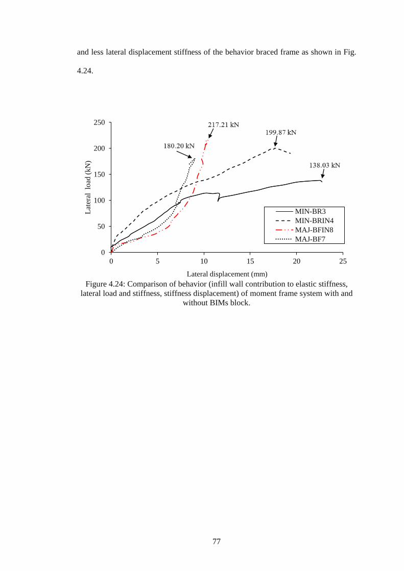
77
and less lateral displacement stiffness of the behavior braced frame as shown in Fig.
4.24.
Figure 4.24: Comparison of behavior (infill wall contribution to elastic stiffness,
lateral load and stiffness, stiffness displacement) of moment frame system with and
without BIMs block.
0
50
100
150
200
250
0 5 10 15 20 25
Lat
eral
lo
ad (
kN
)
Lateral displacement (mm)
MIN-BR3
MIN-BRIN4
MAJ-BFIN8
MAJ-BF7
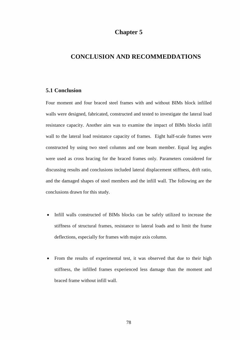
78
Chapter 5
5. CONCLUSION AND RECOMMEDDATIONS
5.1 Conclusion
Four moment and four braced steel frames with and without BIMs block infilled
walls were designed, fabricated, constructed and tested to investigate the lateral load
resistance capacity. Another aim was to examine the impact of BIMs blocks infill
wall to the lateral load resistance capacity of frames. Eight half-scale frames were
constructed by using two steel columns and one beam member. Equal leg angles
were used as cross bracing for the braced frames only. Parameters considered for
discussing results and conclusions included lateral displacement stiffness, drift ratio,
and the damaged shapes of steel members and the infill wall. The following are the
conclusions drawn for this study.
Infill walls constructed of BIMs blocks can be safely utilized to increase the
stiffness of structural frames, resistance to lateral loads and to limit the frame
deflections, especially for frames with major axis column.
From the results of experimental test, it was observed that due to their high
stiffness, the infilled frames experienced less damage than the moment and
braced frame without infill wall.
79
The lateral load versus lateral displacement curves for tested frames with infill
walls showed weaving behavior while graphs of tested frames without infill
walls (ductile systems) show softening or hardening behavior.
The tested moment frames MIN-MFIN2 and MAJ-MFIN6 had diagonal
compression cracks in the infill wall. Therefore, the masonry infill wall acted as
an equivalent compression strut, like a diagonal compression brace to resist the
lateral loading.
Corner crushing due to compression was the dominant failure mode for braced
test frames MIN-BRIN4 and MAJ-BFIN8 with infill wall. The use of infill wall
with braced frame made the bracing more stiff and prolonged its buckling
therefore increased the stiffness of the braced frame agains lateral load.
Overall the bracing frame with infill wall behaves better than the moment frame
with infill wall which is a result of the fact that the bracing frame with infill wall
displays less damage of members and it shows more stiffness when subjected to
lateral load.
Specimens with major axis column orientation exhibited considerably larger
initial stiffness and ultimate lateral load than those with minor axis column
orientation but the latter attained greater ductility.
Furthermore, considering the moment frame, for both major axis and minor axis
without infill wall displayed higher ductility as can be seen on the graphs with
high displacements. As for the braced frames, higher ductility was observed in

80
the column minor axis braced frame without infill wall and the column major
axis braced frame with infill wall.
The lateral displacements of the frames are greatly reduced by the use of
major axis column orientation when compared to minor axis column orientation.
As a result, it can be concluded that use major axis column orientation leads to
reduction in lateral frame displacements when compared to using minor axis
column orientation.
The lateral stiffness of the braced frame with and without infill wall increased
and the lateral displacement decreased significantly when compared to moment
frame with and without infill wall.
The lateral displacements of the frames with and without infill walls are
greatly reduced by the using bracing frame than using moment frame As a
result, it can be concluded that bracing system has more influence on the lateral
displacement. However, the elastic region of the moment frame more higher
than the elastic region of bracing frame.
5.2 Recommendations
Based on the research presented in this thesis, the following are the recommendations
for future work:
In the research, the behavior of moment and braced frame with and without
infilled wall subjected to lateral load has been studied. However, in practice,
81
different types of bracing as V-bracing, Z-bracing, etc. can be used. The
difference in types of bracing is expected to have influence on the overall
frame beahviour. Therefore, similar work can be carried out by using
different types of common bracing systems.
Allowing some gap between the steel frmae and the infill wall is expected to
give more ductile behavior and may be even more stiffness to the frame. This
gap will allow more rotation for the column and beam for frames with infill
walls. So this case can be further investigated to find out possible benefits for
steel frames subjected to lateral loads.
Use of the beam at the bottom as well will increase the stiffness in terms of
behavior in resisting the lateral loading. In particular most construction use a
beam and the top and also the bottom except at the ground level.

82
REFERENCES
[1] Nourbakhsh, S.M. December, (2011.) “Inelastic Behavior of Eccentric Braces
in Steel Structure.”
[2] Jagadish, S., & Doshi, T. Jul, (2013). “A Study On Bracing Systems On High
Rise Steel Structures,” vol. Vol.2 - Is, no. Vol.2 - Issue 7.
[3] K, Stavroula. October, (1999). “Inelastic earthquake response and design of
multistorey torsionally”.
[4] Nakashima, M., & Praween, C. (2003). “A Partial View of Japanese Post-
Kobe Seismic Design and Construction Practices”.
[5] Mohammed, N., & Islam, N. (2013). “Behaviour of Multistorey RCC
Structure with Different Type of Bracing System ( A Software Approach ),”
Int. J. Innov. Res. Sci. Eng. Technol., vol. 2, no. 12, pp. 7465–7478.
[6] LIU, Yu-Shu., & LI, Guo-Qiang. (2004). “Behavior of Steel Frames With and
Without AAC Infilled Walls Subjected to Static and Cyclic Horizontal
Loads,” 13th World Conf. Earthq. Eng., no. 1787, pp. 1–11.
[7] Kapse, M., & Shinde, R. (2015). “Survey Paper on Behaviour of Multi-Storied
R . C . C . FRAME STRUCTURE,” pp. 2319–2163.
83
[8] Ruey Shyang, Ju., Lee, H., Chen, C., & Tao, C. (2012). “Experimental Study
on Separating Reinforced Concrete Infill Walls From Steel Moment Frames,”
J. Constr. Steel Res., vol. 71, pp. 119–128.
[9] Lee, D., Kim, H-G., & Hah, C. (May 2002). “Efficient seismic analysis of
high-rise building structures with the effects of floor slabs,” Eng. Struct., vol.
24, no. 5, pp. 613–623.
[10] Songzhi, X., Jiacheng, L., & Tao, P. Jun, (2013). “Analysis on Seismic
Property of Steel Frame,” Int. Conf. Digit. Manuf. Autom.
[11] Kapse, D., & Shinde, R.. (2015). “Survey Paper on Behaviour of Multi-
Storied R . C . C . Frame Structure.,” IJRET Int. J. Res. Eng. Technol., pp.
2319–2322.
[12] Baikerikar, A., and Kanagali, K. (2014). “Study of Lateral Load Resisting
Systems of Variable Heighis in All Soil Types of High Seismic Zone,” pp.
109–119.
[13] Nakashima, M., Inoue, K., & Tada, M. Apr. (1998). “Classification of damage
to steel buildings observed in the 1995 Hyogoken-Nanbu earthquake,” Eng.
Struct., vol. 20, no. 4–6, pp. 271–281.

84
[14] Reyes-Salazar, A., López-Barraza, A., Rivera-Leyva, O., & R.- Ramírez, J.
Oct , (2008). “Seismic Behavior of Perimeter Moment Resisting Steel
Frames,” 14 th World Conf. Earthq. Eng.
[15] FEMA-310, “Handbook for the Seismic Evaluation of Buildings , 1998,” Fed.
Emerg. Manag. Agency, 1998.
[16] Mazzolani, A., Georgescu, F., & Astaneh. (1995). Remarks on Behaviour of
Concentrically and Eccentrically Braced Steel Frames. CRC Press,
[17] Tafheem, Z., & Khusru., S. (2013). “Structural Behavior of Steel Building
with Concentric and Eccentric Bracing : A comparative study,” vol. 4, no. 1,
pp.
[18] Bartera, F., & Giacchetti., R. “Steel dissipating braces for upgrading existing
building frames,” J. Constr. Steel Res., vol. 60, no. 3–5, pp. 751–769, Mar.
2004.
[19] Di Sarno, L., & Elnashai, A. (2009). “Bracing systems for seismic retrofitting
of steel frames,” J. Constr. Steel Res., vol. 65, no. 2, pp. 452–465.
[20] Fukumoto, Y., & Lee, G. (1992). Stability and Ductility of Steel Structures
under Cyclic Loading. CRC Press.
[21] Rai, D., & Goel, S. Aug, (2003). “Seismic Evaluation and Upgrading of
Chevron Braced Frames,” J. Constr. Steel Res., vol. 59, no. 8, pp. 971–994.

85
[22] Khatib, I., Mahin, SA., Pister, KS. Aug, (1988). “Seismic Behavior of
Concentrically Braced Steel Frame,” Journal of Structural Engineering. vol.
115, no. 8, p. NO. UCB/EERC–8–01.
[23] McCormick, J., DesRoches, R., Fugazza, D., & Auricchio, F. (2007). “Seismic
Assessment of Concentrically Braced Steel Frames with Shape Memory Alloy
Braces,” Journal of Structural Engineering. vol. 133, no. 6, pp. 862–870.
[24] Bateman, S. (2007). “Parametric Design Aids for Concentric Braced Frame
Systems.”
[25] Bubela, K. April, (2000). “An Experimental and Analytica Study of Chevron
Braced Frames with Vertical Slotted Connections,” B.A.Sc, Univ. Br.
Columbia.
[26] ÖZTÜRK, M. December, (2005). “Effects of Masonry Infill Walls on the
Seismic Performance of Buildings,” Middle East Tech. Univ. Civ. Eng. Thesis.
[27] Paulay, T., &Priestley, N. (1992). “Seismic Design of Reinforced Concrete-
and Masonry Buildings.”
[28] Zovkic, J., Sigmund, V., & Guljas, I. (2013). “Cyclic testing of a single bay
reinforced concrete frames with various types of masonry infill,” Eng. Struct.,
vol. 51, no. 8, pp. 267–277.

86
[29] Liu, Y. & Manesh, P. (2012). “Concrete Masonry Infilled Steel Frames
Subjected to Combined In-plane Lateral and Axial Loading - An experimental
study,” Eng. Struct., vol. 52, pp. 331–339.
[30] Liu, Y. & Soon, S. ( 2012). “Experimental Study of Concrete Masonry Infills
Bounded by Steel Frames.”
[31] Maheri, M., Kousari, R., & Razazan, M. (2003). “Pushover Tests on Steel X-
Braced and Knee-Braced RC frames,” Eng. Struct., vol. 25, no. 13, pp. 1697–
1705.
[32] Amato, G., Fossetti, M., Cavaleri, L., & Papia, M. (2009). “An Updated
Model of Equivalent Diagonal Strut for Infill Panels,” Proc. Eurocode, no. pp.
119–128.
[33] Kameshki, E., & Saka, P. (2001). “Genetic Algorithm Based Optimum
Bracing Design of Non-Swaying Tall Plane Frames,” J. Constr. Steel Res.,
vol. 57, no. 10, pp. 1081–1097.
[34] Jazany, A., Hajirasouliha, I., & Farshchi, H. (2013). “Influence of masonry
infill on the seismic performance of concentrically braced frames,” J. Constr.
Steel Res., vol. 88, pp. 150–163.
[35] Teeuwen, P. (2009). Lateral Behavior of Steel Frames with Discretely
Connected.
87
[36] “Simple connections - Steel construction.info.” [Online]. Available:
http://www.steelconstruction.info/Simple_connections.
[37] Liu, Y., & Manesh, P. (2013). “Concrete masonry infilled steel frames
subjected to combined in-plane lateral and axial loading – An experimental
study,” Eng. Struct., vol. 52, pp. 331–339.

88
APPENDICES
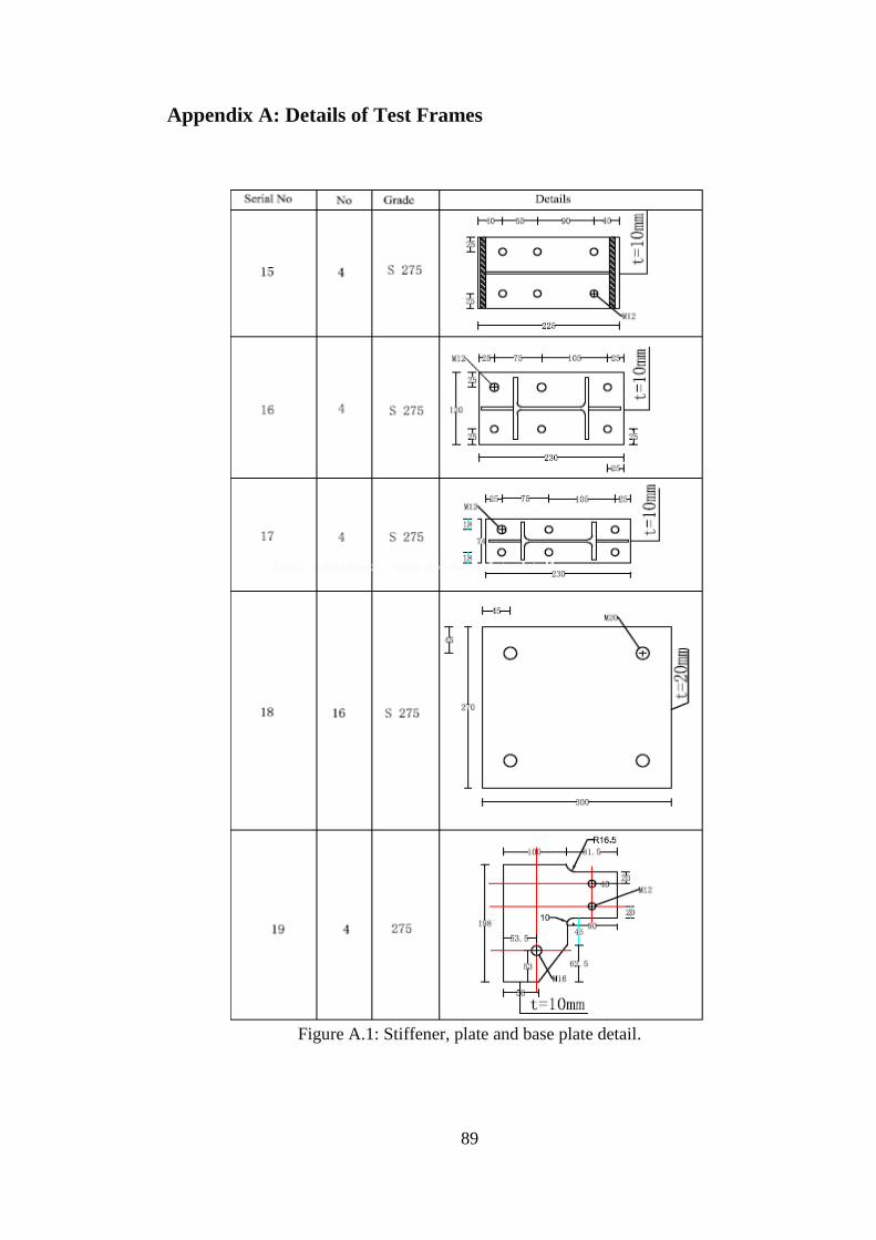
89
Appendix A: Details of Test Frames
Figure A.1: Stiffener, plate and base plate detail.
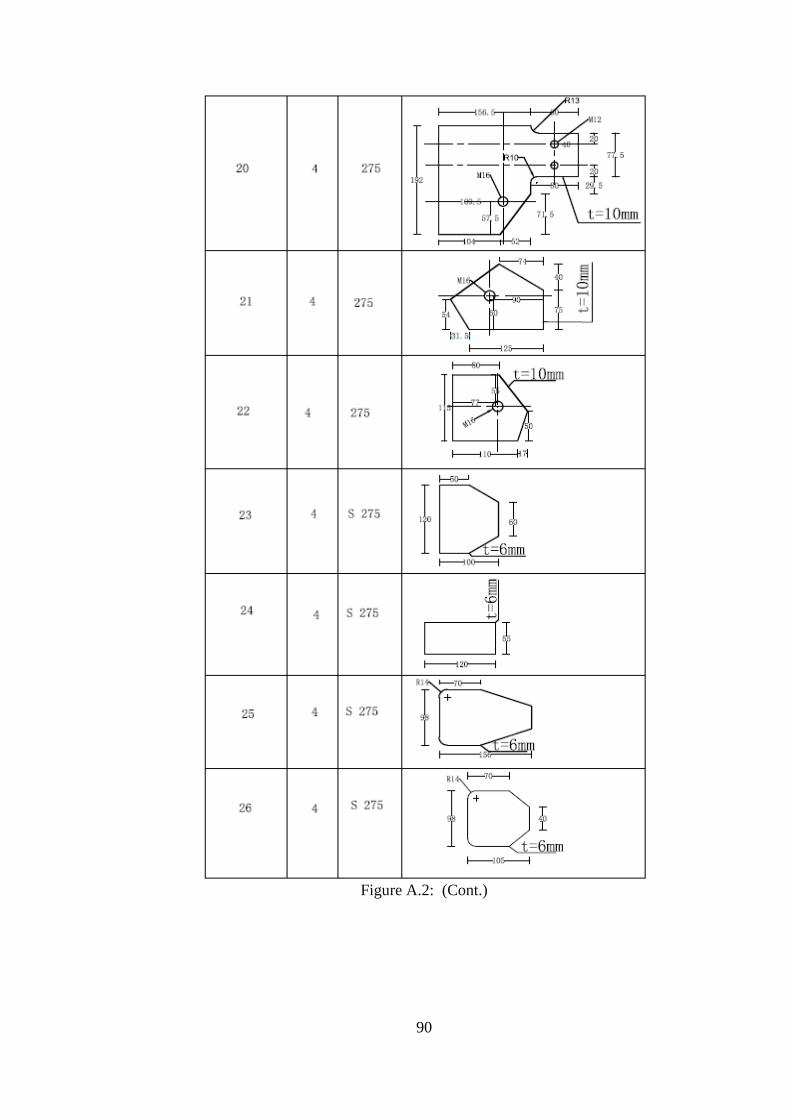
90
Figure A.2: (Cont.)
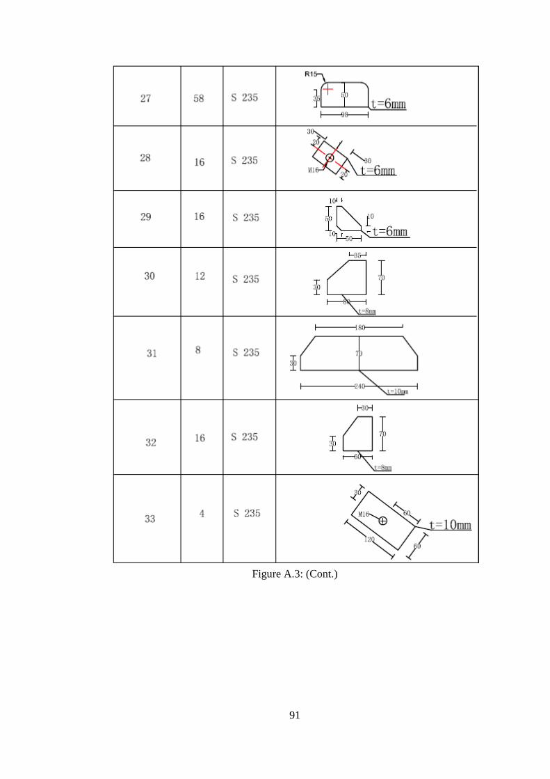
91
Figure A.3: (Cont.)

92
Figure A.4: Dimensions and holes detail of column, beam and bracing.
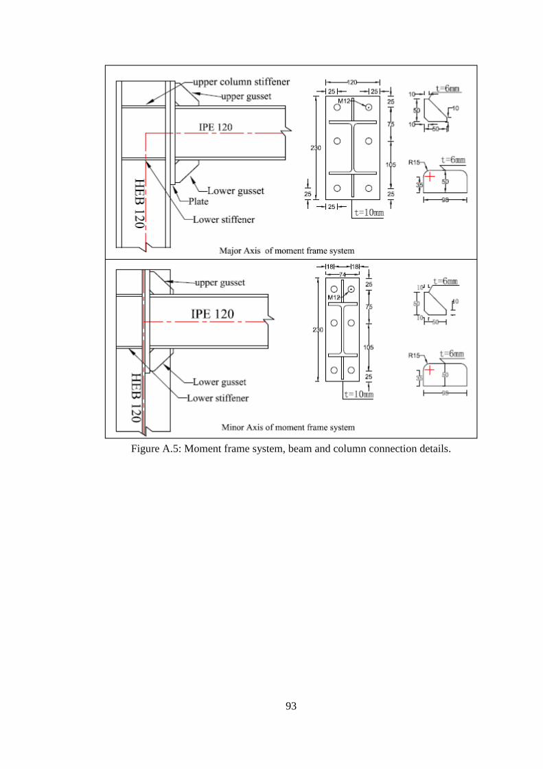
93
Figure A.5: Moment frame system, beam and column connection details.

94
Figure A.6: Braced frame system, beam, column and bracing connection details.
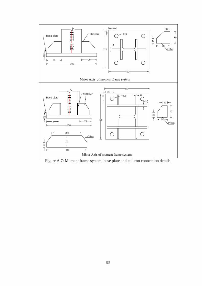
95
Figure A.7: Moment frame system, base plate and column connection details.

96
Figure A.8: Braced frame system, base plate and column connection details.

97
Appendix B: Frame Loading and the Support Frames
Figure B.9: Set up of hydraulic jack with a capacity of 1000 kN.

98
Figure B.10: Set up of test frame LVDTs.
Figure B.11 Set up of test frame MIN-MF1.
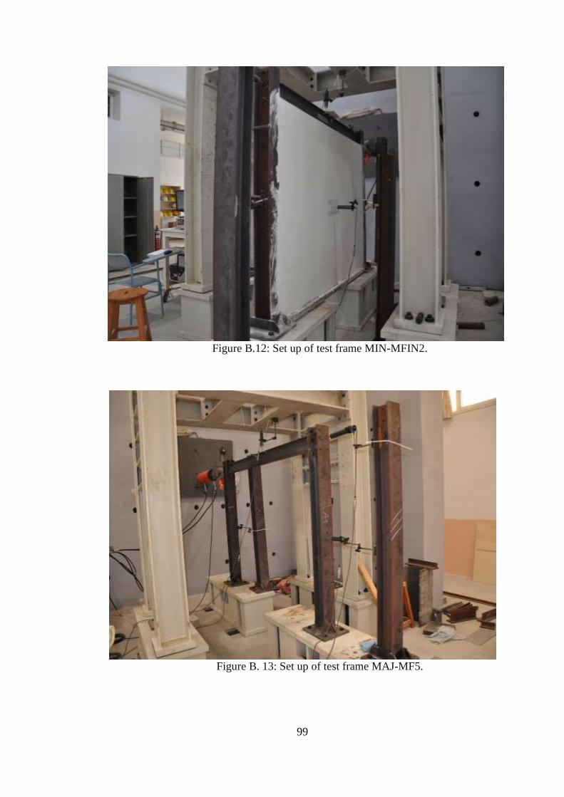
99
Figure B.12: Set up of test frame MIN-MFIN2.
Figure B. 13: Set up of test frame MAJ-MF5.
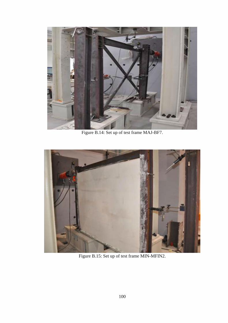
100
Figure B.14: Set up of test frame MAJ-BF7.
Figure B.15: Set up of test frame MIN-MFIN2.