Embed Size (px)
Citation preview

NIST Technical Note 2033
Effect of IF-WS2 Nanolubricant on R134a Boiling on a Reentrant Cavity Surface; Extensive Measurement and
Analysis Details
Mark A. Kedzierski Lingnan Lin
This publication is available free of charge from: https://doi.org/10.6028/NIST.TN.2033

NIST Technical Note 2033
Effect of IF-WS2 Nanolubricant on R134a Boiling on a Reentrant Cavity Surface; Extensive Measurement and
Analysis Details
Mark A. Kedzierski Lingnan Lin
Energy and Environment Division Engineering Laboratory
This publication is available free of charge from: https://doi.org/10.6028/NIST.TN.2033
February 2019
U.S. Department of Commerce Wilbur L. Ross Jr., Secretary
National Institute of Standards and Technology
Walter Copan, NIST Director and Undersecretary of Commerce for Standards and Technology

Certain commercial entities, equipment, or materials may be identified in this document in order to describe an experimental procedure or concept adequately.
Such identification is not intended to imply recommendation or endorsement by the National Institute of Standards and Technology, nor is it intended to imply that the entities, materials, or equipment are necessarily the best available for the purpose.
National Institute of Standards and Technology Technical Note 2033 Natl. Inst. Stand. Technol. Tech. Note 2033, 33 pages (February 2019)
CODEN: NTNOEF
This publication is available free of charge from: https://doi.org/10.6028/NIST.TN.2033
i
Effect of IF-WS2 Nanolubricant on R134a Boiling on a Reentrant
Cavity Surface; Extensive Measurement and Analysis Details
M. A. Kedzierski, and L. Lin National Institute of Standards and Technology
Gaithersburg, MD 20899
ABSTRACT This report quantifies the influence of inorganic fullerene-like tungsten disulfide (IF-WS2) nanoparticles on the pool-boiling performance of R134a/polyolester mixtures on a commercial (Turbo-ESP) boiling surface. Tungsten disulfide nanoparticles, of roughly 150 nm, were used at a 15 % mass fraction in a base polyolester lubricant to produce the test nanolubricant. The nanolubricant was mixed with R134a at a 1 % mass fraction. The study showed that the nanolubricant caused an average 37 % degradation in the boiling heat flux as compared to R134a/neat-lubricant boiling on a reentrant cavity surface at the same superheat. Similarly, boiling with R134a/neat-lubricant caused, on average, a 27 % degradation in the boiling heat flux as compared to pure R134a boiling and the same superheat. An analysis was presented which showed that the nanoparticles were too large and too dense to promote a boiling enhancement. In addition, the fullerene-like structure and the large size encouraged nanoparticle settling, which presumably filled cavities of the boiling surface leading to additional boiling degradations. Keywords: additive, tungsten disulfide, pool boiling, enhanced heat transfer, fullerene, nanolubricant, nanotechnology, refrigerants, refrigerant/lubricant mixtures, structured surface
______________________________________________________________________________________________________ This publication is available free of charge from
: https://doi.org/10.6028/NIST.TN
.2033

ii
TABLE OF CONTENTS ABSTRACT .............................................................................................................................. i TABLE OF CONTENTS ....................................................................................................... ii LIST OF FIGURES ................................................................................................................ ii LIST OF TABLES ................................................................................................................. iii INTRODUCTION................................................................................................................... 1 APPARATUS .......................................................................................................................... 2 TEST FLUIDS ......................................................................................................................... 2 TEST SURFACE .................................................................................................................... 3 MEASUREMENTS AND UNCERTAINTIES .................................................................... 3 EXPERIMENTAL RESULTS ............................................................................................... 4 DISCUSSION .......................................................................................................................... 5 CONCLUSIONS ..................................................................................................................... 7 ACKNOWLEDGEMENTS ................................................................................................... 7 NOMENCLATURE ................................................................................................................ 9 English Symbols ...................................................................................................................... 9 Greek Symbols ........................................................................................................................ 9 English Subscripts ................................................................................................................... 9 REFERENCES ...................................................................................................................... 10 APPENDIX A: UNCERTAINTIES .................................................................................... 26
LIST OF FIGURES Fig. 1 Schematic of test apparatus ...................................................................................... 19 Fig. 2 OFHC copper flat test plate with the Turbo-ESP surface and thermocouple
coordinate system ...................................................................................................... 20 Fig. 3 Photograph of the Turbo-ESP surface .................................................................... 21 Fig. 4 R134a and R134a/RL32 (99/1) mixture boiling curves for the Turbo-ESP surface
..................................................................................................................................... 22 Fig. 5 Boiling heat flux ratio of R134a/RL32 (99/1) for the Turbo-ESP surface ........... 23 Fig. 6 R134a/RL32 and R134a/nanolubricant mixtures boiling curves for the Turbo-
ESP surface ................................................................................................................ 24 Fig. 7 Boiling heat flux ratio of R134a/nanolubricant mixture for the Turbo-ESP
surface ........................................................................................................................ 25 Fig. A.1 Expanded relative uncertainty in the heat flux of the surface at the 95 %
confidence level.......................................................................................................... 26 Fig. A.2 Expanded uncertainty in the temperature of the surface at the 95 % confidence
level ............................................................................................................................. 27
______________________________________________________________________________________________________ This publication is available free of charge from
: https://doi.org/10.6028/NIST.TN
.2033

iii
LIST OF TABLES Table 1 Pool boiling data ..................................................................................................... 12 Table 2 Number of test days and data points .................................................................... 15 Table 3 Estimated parameters for cubic boiling curve fits for Turbo-ESP copper
surface ........................................................................................................................ 16 Table 4 Residual standard deviation of ∆Ts ...................................................................... 17 Table 5 Average magnitude of 95 % multi-use confidence interval for mean ∆Ts ........ 18
______________________________________________________________________________________________________ This publication is available free of charge from
: https://doi.org/10.6028/NIST.TN
.2033

1
INTRODUCTION The National Energy Conservation Policy Act (NECPA, 1978) requires federal agencies to reduce the energy requirements of their buildings. Air conditioning is a significant portion of a large building’s energy consumption (US EIA, 2012). Consequently, a retroactive improvement in the energy efficiency of existing water chillers that cool large buildings would contribute to the effort of federal agencies to meet the goals of the NECPA. One proposed retroactive and cost-effective method for reducing chiller operating costs is to replace the chiller lubricant with a nanolubricant. Nearly all vapor-compression refrigeration systems require a lubricating oil to be charged into the system along with the refrigerant. Although the lubricant is only necessary for the operation of the compressor, it is an unavoidable consequence that it will circulate through the heat exchangers along with the refrigerant and possibly degrade the performance of the system. Nanolubricants offer the opportunity of improving boiling heat transfer. Studies by Henderson et al. (2010), Bi et al. (2007), Peng et al. (2011), Hu (2013), and Kedzierski (2009) have explored the use of nanolubricants as a means for improving efficiencies of air conditioning and refrigeration equipment. For low flow qualities, Henderson et al. (2010) have shown that CuO nanoparticles can improve the flow boiling heat transfer of refrigerant/lubricant mixtures by as much as 76 % and that the lubricant can act as a necessary dispersant. Peng et al. (2010) have shown that diamond nanolubricants can improve refrigerant/lubricant pool boiling by as much as 63 %. Similarly, copper-oxide nanoparticles have also been shown to improve refrigerant/lubricant pool boiling by as much as 245 % (Kedzierski and Gong, 2009). These preceding studies suggest that it is worth investigating the potential benefits of commercially available nanolubricants for large commercial chillers. One of the few commercially available nanolubricants is based on inorganic fullerene-like tungsten disulfide (IF-WS2) nanoparticles. Typically, only organic compounds are fullerene. Fullerene describes the shape of the nanoparticle as being non-spherical and ellipsoidal. Most of the nanolubricant studies for boiling applications have been done with spherical metal oxides. No refrigerant/nanolubricant boiling studies with metal sulfides were found in the current literature. Consequently, the scope of the present investigation was to determine if IF-WS2 nanoparticles are able to improve the boiling performance of R134a/lubricant boiling. Boiling tests of a R134a/nanolubricant mixture were made on the horizontal, flat, copper, finned, Turbo-ESP1 surface. A commercial polyolester lubricant (RL32) with a nominal kinematic viscosity of 31.2 µm2s-1 at 313.15 K was the base lubricant that was mixed with nominally 100 nm – 150 nm diameter IF-WS2 nanoparticles. IF-WS2 nanoparticles have the advantages of a well-established, successful dispersion technology and being extensively used to lubricate engines and other devices with wear parts. The established commercial nature of the IF-WS2 nanolubricants, satisfied a
1 Certain trade names and company products are mentioned in the text or identified in an illustration in order to adequately specify the experimental procedure and equipment used. In no case does such an identification imply recommendation or endorsement by the National Institute of Standards and Technology, nor does it imply that the products are necessarily the best available for the purpose.
______________________________________________________________________________________________________ This publication is available free of charge from
: https://doi.org/10.6028/NIST.TN
.2033

2
primary part of the project scope, which was to determine if a commercially available nanolubricant could be used to enhance chiller performance. APPARATUS Figure 1 shows a schematic of the apparatus that was used to collect the pool boiling data. More specifically, the apparatus was used to measure the liquid saturation temperature (Ts), the average pool-boiling heat flux (q"), and the wall temperature (Tw) of the test surface. The three principal components of the apparatus were a test chamber containing the test surface, the condenser, and the purger. The internal dimensions of the test chamber were 25.4 mm × 257 mm × 1.54 m. The test chamber was charged with approximately 7 kg of refrigerant, giving a liquid height of approximately 80 mm above the test surface. As shown in Fig. 1, the test section was visible through two opposing, flat 150 mm × 200 mm quartz windows. The bottom of the test surface was heated with high velocity (2.5 m/s) water flow. The vapor produced by liquid boiling on the test surface was condensed by the brine-cooled, shell-and-tube condenser and returned as liquid to the pool by gravity. Further details of the test apparatus can be found in Kedzierski (2002) and Kedzierski (2001). TEST FLUIDS The manufacturer used a proprietary surfactant at a mass between 8 % and 9 % of the mass of the IF-WS2 as a dispersant for the RL32/IF-WS2 mixture (nanolubricant). The manufacturer made the mixture such that approximately 15 % of the mass was IF-WS2 particles, which have a nominal density of 7500 kg m-3. For brevity, the RL32/IF-WS2 (85/15) mass fraction nanolubricant in this study is identified as WS2. The number-weighted sizes of the nanoparticles in the nanolubricant were measured with a Dynamic Light Scattering (DLS) technique using a 633 nm wavelength. An index of refraction of 1.33 for tungsten disulfide was used in the Brownian motion-based calculation that was done internally by the DLS instrument for the particle size. The uncertainty of the packaged DLS instrumentation was confirmed with a NIST-metrological-traceable 60 nm ± 2.7 nm nanofluid size-standard. The measured diameter of the size-standard with the DLS system was 64 nm ± 5 nm, which coincides with the range of uncertainty of the standard. The DLS measurements showed that the average equivalent diameters on a number-weighted basis for the IF-WS2 nanoparticles were 154 nm ± 36 nm, which is near the manufacturer’s quoted nominal range of 100 nm to 150 nm. The larger uncertainty of 36 nm is a consequence of the wide variation in nanoparticle size.
______________________________________________________________________________________________________ This publication is available free of charge from
: https://doi.org/10.6028/NIST.TN
.2033

3
TEST SURFACE Figure 2 shows the oxygen-free high-conductivity (OFHC) copper flat test plate used in this study. The test plate was machined out of a single piece of OFHC copper by electric discharge machining (EDM). The internal fins of a commercial 25 mm (outer-diameter) Turbo-ESP tube were removed by EDM. The tube was then cut axially, annealed, flattened, and soldered onto the top of the test plate. Figure 3 shows a photograph of the fin surface. The Turbo-ESP has approximately 1968 fins per meter (fpm) oriented along the short axis of the plate. The overall fin-height and the width of the surface openings at the fin-tips are approximately 0.4 mm and 0.04 mm, respectively. MEASUREMENTS AND UNCERTAINTIES The standard uncertainty is the square root of the estimated variance of the measurement. The individual standard uncertainties are combined to obtain the expanded uncertainty (U), which is calculated from the law of propagation of uncertainty with a coverage factor. All measurement uncertainties are reported at the 95 % confidence level except where specified otherwise. Further details on the heat transfer measurement uncertainties are available in Appendix A. All of the copper-constantan thermocouples and the data acquisition system were calibrated against a glass-rod standard platinum resistance thermometer (SPRT) and a reference voltage to a residual standard deviation of 0.005 K. The reference voltage enabled the correction for any drift in the voltage measurement over time. Considering the fluctuations in the saturation temperature during the test and the standard uncertainties in the calibration, the expanded uncertainty of the average saturation temperature was no greater than 0.04 K. Consequently, it is estimated that the expanded uncertainty of the temperature measurements was less than 0.1 K. Twenty 0.5 mm diameter thermocouples were force-fitted into the wells of the side of the test plate shown in Fig. 2. The heat flux and the wall temperature were obtained by regressing the measured temperature distribution of the block to the governing two-dimensional conduction equation (Laplace equation). In other words, rather than using the boundary conditions to solve for the interior temperatures, the interior temperatures were used to solve for the boundary conditions following a backward stepwise procedure given in Kedzierski (1995). As shown in Fig. 2, the origin of the coordinate system was centered on the surface with respect to the y-direction at the heat transfer surface. Centering the origin in the y-direction reduced the uncertainty of the wall heat flux and temperature calculations by reducing the number of fitted constants involved in these calculations. Fourier's law and the fitted constants from the Laplace equation were used to calculate the average heat flux (q") normal to and evaluated at the heat transfer surface based on its projected area. The average wall temperature (Tw) was calculated by integrating the local wall temperature (T). The wall superheat was calculated from Tw and the measured temperature of the saturated liquid (Ts). Considering this, the relative expanded uncertainty in the heat flux (Uq") was greatest at the lowest heat fluxes, approaching 12 % of the measurement near 10 kWm-2. In general, the Uq" remained between 3 % and 7 % for heat fluxes greater than 20 kWm-2. The average random error in the wall superheat (UTw) remained mainly between 0.06 K and 0.12 K with an average
______________________________________________________________________________________________________ This publication is available free of charge from
: https://doi.org/10.6028/NIST.TN
.2033

4
value of approximately 0.09 K. Plots of Uq" and UTw versus heat flux are available in Appendix A. EXPERIMENTAL RESULTS The heat flux was varied between approximately 10 kWm-2 and 120 kWm-2 to simulate a range of possible operating conditions for R134a chillers. All pool-boiling measurements were made at 277.6 K saturated conditions. The data were recorded consecutively starting at the largest heat flux and descending in intervals of approximately 4 kWm-2. The descending heat flux procedure minimized the possibility of any hysteresis effects on the data, which would have made the data sensitive to the initial operating conditions. Table 1 presents the measured heat flux and wall superheat data. Table 2 summarizes the number of test days and data points for each fluid. A total of 398 measurements were made over 16 days. The test fluid was prepared by charging the test chamber (see Fig. 1) with pure R134a of a known mass. Next, a measured mass of nanolubricant or lubricant was injected with a syringe through a port in the test chamber. The refrigerant/lubricant solution was mixed by flushing pure refrigerant through the same port where the lubricant was injected. All compositions were determined from the masses of the charged components and are given on a mass fraction basis. The maximum uncertainty of the lubricant mass fraction (xb) measurement is approximately 0.02 %, e.g., the range of a 1.0 % mass fraction is between 0.98 % and 1.02 %. The nominal or target mass composition is used in the discussion. For example, the “actual” mass composition of the RL32 in the R134a/RL32 (99/1) mixture was 0.99 % ± 0.02 %. Similarly, the mass composition of WS2 in the R134a/WS2 (99/1) was 0.94 % ± 0.02 %. Figure 4 is a plot of the measured boiling heat flux ( "q ) of the neat R134a and the Rl34a/RL32 (99/1) mixture versus the measured wall superheat (Tw - Ts = ∆Ts) for the Turbo-ESP at a saturation temperature of 277.6 K. The open symbols represent the measured data while the solid line is a cubic best-fit regression or estimated means of the data. Seven days of R134a boiling produced 173 measurements over a period of approximately one week. Eight of the 173 measurements were identified as “outliers” based on having both high influence and high leverage (Belsley et al., 1980) and removed before fitting. The data sets for each test fluid presented in this manuscript exhibited a similar number of outliers and were regressed in the same manner. Table 3 gives the constants for the cubic regression of the superheat versus the heat flux for all of the fluids tested here. The residual standard deviation of the regressions – representing the proximity of the data to the mean – are given in Table 4 and are, on average, approximately 0.09 K. The dashed lines to either side of the mean represent the lower and upper 95 % simultaneous (multiple-use) confidence intervals for the mean and are, for the most part, concealed by the data symbols. From the confidence intervals, the expanded uncertainty of the estimated mean wall superheat was, on average, 0.05 K. Table 5 provides the average magnitude of the 95 % multi-use confidence interval for the fitted wall superheat for all of the test data. The R134a pool boiling measurements of Gorgy (2016) and Kedzierski et al. (2018) for the Turbo-ESP surface are shown as dashed lines on Fig. 4. The Kedzierski et al. (2018) data are within 10 % of most of the present measurements. The Gorgy (2016) measured heat flux is roughly 30 % less than the present measurements. The larger difference between the present measurements and the Gorgy (2016) may be due to slight differences in the surface structure
______________________________________________________________________________________________________ This publication is available free of charge from
: https://doi.org/10.6028/NIST.TN
.2033

5
between tube production runs and because the Gorgy (2016) data were for a round tube while the data for the present study are for a flat plate. The R134a measurements serve as a baseline for comparison to the R134a/RL32 (99/1) measurements. “Break-in” data had to be taken in order to allow sufficient time for the lubricant excess layer to be established on the heat transfer surface. The first three days of boiling measurements were considered break-in data and were not included in the analyzed data set because they differed significantly from the remaining measurements. Figure 4 shows that the 1 % mass addition of lubricant to R134a has caused a roughly 30 % reduction in the heat flux for a given superheat. A more precise illustration of the effect of the lubricant on the boiling heat transfer is given in Fig. 5. Figure 5 plots the ratio of the heat flux for R134a/RL32 (99/1) to the heat flux for R134a (q"RL/q" R) versus the heat flux for R134a (q" R) at the same wall superheat. Figure 5 illustrates the influence of the neat lubricant on the R134a boiling curve with a solid line representing the mean heat flux ratio and dashed lines showing the 95 % multi-use confidence interval for the mean. A heat transfer degradation exists where the heat flux ratio is less than one and the 95 % simultaneous confidence intervals do not include the value one. Figure 5 shows that the lubricant degrades the boiling performance of R134a. The smallest degradation occurred for the smallest heat flux of approximately 14 kWm-2 at a ratio of 0.92 ± 0.15. The largest degradation, 0.56 ± 0.02, occurred for the largest heat fluxes of approximately 98 kWm-2. Averaged over the entire heat flux test range, the degradation was approximately 27 %. Figure 6 shows the boiling curves for R134a/RL32 (99/1) and R134a/WS2 (99/1). The comparison shows that the boiling performance of the R134a/WS2 (99/1) mixture is significantly less than that of R134a/RL32 (99/1) indicating that the nanoparticles have caused a heat transfer degradation. Figure 7 shows the heat flux ratio for these fluids. Figure 7 shows that the nanolubricant degrades the boiling performance of R134a/RL32 (99/1). The smallest degradation occurred for the smallest heat flux of approximately 14 kWm-2 at a ratio of 0.85 ± 0.24. The largest degradation, 0.53 ± 0.05, occurred for the largest heat fluxes of approximately 98 kWm-2. The WS2 nanolubricant caused an average 37 % degradation in the boiling heat flux as compared to R134a/neat-lubricant boiling on a reentrant cavity surface. DISCUSSION The following discussion uses a previously developed refrigerant/nanolubricant mixture pool boiling model to show that the WS2 nanolubricant failed to improve the boiling performance of R134a/RL32 because both the size and the density of the IF-WS2 nanoparticles were too large. Kedzierski (2015) modeled refrigerant/nanolubricant boiling heat transfer enhancement as a consequence of bubbles impacting nanoparticles as they rise through the lubricant excess layer. The nanoparticle surface density (Nnp/As) represents a key parameter in the model for determining the magnitude of the boiling enhancement with nanolubricants. Here, Nnp is the total number of nanoparticles that reside in the lubricant excess layer on the boiling surface and As is the active surface area of the boiling test plate. For the present study, the nanolubricant surface density can be conservatively estimated from the charged mass of the nanolubricant
______________________________________________________________________________________________________ This publication is available free of charge from
: https://doi.org/10.6028/NIST.TN
.2033

6
(MNL), the nanolubricant mass fraction (xNL), the density of the nanoparticle (ρnp), and the nanoparticle effective diameter (Dnp) as:
np 16 2NL NL3
s s np np
6 5 10 mN x MA A Dπ ρ
−= ≅ × (1)
The surface area of the test section (As) was estimated as 0.008 m2. Equation (1) was derived while assuming that all of the nanoparticles reside in the lubricant excess layer and that the nanoparticles are spherical; both assumptions lead to an overestimation of the nanoparticle surface density. Kedzierski (2015) has shown that values of Nnp/As less than 7 × 10¹⁹ m-2 tend to lead to boiling heat transfer degradations. The approximate value given in eq. (1) is several orders of magnitude smaller than this because of the relatively large nanoparticle diameter and the large nanoparticle density of IF-WS2, which are evaluated in the denominator of eq. (1). Boiling enhancements have been previously observed for metal oxide nanoparticles with diameters of the order of 10 nm to 40 nm and densities less than 4000 kg m-3. The Kedzierski (2015) model requires a surface geometry dependent nanoparticle surface density, (Nnp/As)G, to account for the nonuniform bubble activity on the surface and its variation with the heat flux. An expression for (Nnp/As)G does not currently exist for the Turbo-ESP surface; however, (Nnp/As)G can be approximated by using an expression for the Turbo-BII-HP surface:
( )1.47
2.53np np8 " 20 "n n
s sG
4.15 10 1 10 0.00017N N
q qA A
− = × ⋅ × +
(2)
where "
nq is equal to "RLq normalized by dividing by 1 -2W m⋅ . The approximation should be
valid because the two surfaces have similar structure and surface area per projected area ratios. Equation 3 gives the boiling heat transfer model for refrigerant/aluminum oxide nanolubricant mixtures valid for a plain surface and a rectangular-finned surface as a function of surface geometry dependent nanoparticle surface density; (Nnp/As)G (Kedzierski, 2015):
( ) ( )
np9 1L v"
sNL G3/2" " 2
RL np n RL np RL
1.45 10 [s m ]1
(1 )
Nx
Aqq D q g x
σν ρ
ρ ρ ρ
− −× ⋅
= +− −
(3)
Properties included in eq. (3) are the refrigerant surface tension (σ), the refrigerant vapor density (ρv), the neat lubricant liquid density (ρRL) and liquid kinematic viscosity (νL), and the nanoparticle density (ρnp). For eq. (3), the bulk nanolubricant mass fraction and the lubricant mass fraction are the same (x) because they are compared at the same value and equal to 0.01 for this study.
______________________________________________________________________________________________________ This publication is available free of charge from
: https://doi.org/10.6028/NIST.TN
.2033

7
Evaluation of eq. (3), for the range of heat fluxes of this study, resulted in values essentially equal to one. Equation (3) does not predict the degradation exhibited in Fig. 5 because the model assumes that the nanoparticles make a stable suspension in the nanolubricant excess layer and remain there. However, both the larger Dnp and the fullerene-like structure of the nanoparticles act against stable nanoparticles in the excess layer. First, larger particles settle more quickly than smaller ones. Second, the fullerene-like structure gives the nanoparticle “sticky” characteristics that encourages nanoparticle deposition on the boiling surface. Joly-Pottuza et al. (2005) discuss how the shape of IF-WS2 is associated with dangling bonds, which is associated with surface adhesion. By comparison, spherical nanoparticles do not have dangling bonds, which makes them chemically inert and not prone to surfaces adhesion (Joly-Pottuza et al., 2005). Consequently, spherical nanoparticles like Al2O3 tend to remain in the lubricant excess layer and not get lodged in the boiling surface cavities. In contrast, fullerene-like nanoparticles are more likely to deposit within boiling cavities and cause a heat transfer degradation due to a reduction in active boiling cavities. The model cannot predict the degradation due to loss of cavity sites. Future research should be done on commercially available nanolubricants that are manufactured using nanoparticles with effective diameters smaller than 40 nm and with densities less than 4000 kg m-3 to explore the potential for enhancing the boiling performance of refrigerant/lubricant mixtures. In addition, refrigerant/nanolubricant boiling performance should be evaluated for nanoparticles of the same effective size and material, but for fullerene-like and spherical shapes in order to verify the effect of the fullerene-like shape on boiling. CONCLUSIONS The effect of inorganic fullerene-like tungsten disulfide (IF-WS2) nanoparticles on the pool boiling performance of R134a/polyolester mixtures on a commercial (Turbo-ESP) boiling surface was investigated. A nanolubricant with size ranges between 100 nm and 150 nm IF-WS2 nanoparticles at a 15 % mass fraction in the base polyolester lubricant was mixed with R134a at a 1 % mass fraction. The study showed that the nanolubricant caused an average 37 % degradation in the boiling heat flux as compared to R134a/neat-lubricant boiling on a reentrant cavity surface. Similarly, boiling with R134a/neat-lubricant caused, on average, a 27 % degradation in the boiling heat flux as compared to pure R134a boiling. A pool boiling model was used to show that the nanoparticles were too large and too dense to expect a boiling enhancement. In addition, the fullerene-like structure and the relatively large size promoted nanoparticle settling to the cavities of the boiling surface, which presumably contributed to the boiling heat transfer degradation. ACKNOWLEDGEMENTS This work was funded by the Naval Facilities Engineering & Expeditionary Warfare Center (NAVFAC EXWC) through United States Interagency Agreement N6921817MP10015 under project manager P. Kistler. Appreciation is expressed to N. Sawant of Whirlpool Corporation and to the following NIST personnel for their constructive criticism of the draft manuscript: R. Zarr and P. Domanski. Furthermore, the author extends appreciation to A. Heckert of the NIST Statistical Engineering Division for his consultations on the uncertainty analysis. The authors
______________________________________________________________________________________________________ This publication is available free of charge from
: https://doi.org/10.6028/NIST.TN
.2033

8
acknowledge G. Chaubey of Nanotech Industrial Solutions for supplying the RL32/IF-WS2 (85/15) nanolubricant.
______________________________________________________________________________________________________ This publication is available free of charge from
: https://doi.org/10.6028/NIST.TN
.2033

9
NOMENCLATURE English Symbols An regression constant in Table 3 n=0,1,2,3 As heat transfer surface area, m2 Dnp nanoparticle diameter, m g gravitational acceleration, m·s-2 L test surface length shown in Fig. 2, m Nnp the number of nanoparticles Nnp/As nanoparticle surface density, m-2 q" average wall heat flux, W·m-2
"nq
"RL
-21W mq
=⋅
T temperature, K Tw temperature at roughened surface, K U expanded uncertainty x mass fraction Greek Symbols ∆Ts wall superheat: Tw - Ts, K ν kinematic viscosity, m2·s-1 σ surface tension of refrigerant, N·m-1 ρ density, kg·m-3 English Subscripts np nanoparticle R pure R134a RL refrigerant/pure lubricant (R134a/RL32) mixture NL refrigerant/nanolubricant (R134a/WS2) mixture q" heat flux s saturated state Tw wall temperature v vapor
______________________________________________________________________________________________________ This publication is available free of charge from
: https://doi.org/10.6028/NIST.TN
.2033

10
REFERENCES Belsley, D. A., Kuh, E., and Welsch, R. E. 1980. Regression Diagnostics: Identifying Influential Data and Sources of Collinearity, New York: Wiley. Bi, S., Shi, L., and Zhang, L. 2007. Performance Study of a Domestic Refrigerator Using R134a/Mineral Oil/Nano-TiO2 as Working Fluid, Proceedings of International Conference of Refrigeration, Beijing, ICRO7-B2-346. Gorgy, E. 2016. Nucleate boiling of low-GWP refrigerants on highly enhanced tube surface, Int. J. Heat Mass Transfer, 96, 660–6. Henderson, K., Park, Y., Liu, L., Jacobi, A. M. 2010. Flow-Boiling Heat Transfer of R-134a-Based Nanofluids in a Horizontal Tube, IJHMT, 53, 944-951 Hu, H., Peng, H., and Ding, G. 2013. Nucleate Pool Boiling Heat Transfer Characteristics of Refrigerant/Nanolubricant Mixture with Surfactant, Int. J. Refrigeration, 36, 1045-1055. Joly-Pottuza, L., Dassenoya, F., Belina, M., Vachera, B., Martina J.M., and Fleischerb, N. 2005. Ultralow-friction and wear properties of IF-WS2 under boundary lubrication, Tribology Letters, 18(4), 477-485. DOI: 10.1007/s11249-005-3607-8 Kedzierski, M. A., Lin, L., and, Kang, D. Y. 2018. Pool Boiling of Low GWP Replacements for R134a on a Reentrant Cavity Surface, J. Heat Transfer, 140(12), doi:10.1115/1.4040783. Kedzierski, M. A. 2015. Effect of Concentration on R134a/Al2O3 Nanolubricant Mixture Boiling on a Reentrant Cavity Surface, Int. J. Refrigeration, 49, 36-38. Kedzierski, M. A. 2009. Effect of CuO Nanoparticle Concentration on R134a/Lubricant Pool-Boiling Heat Transfer, ASME J. Heat Transfer, 131(4), 043205. Kedzierski, M. A., and Gong, M. 2009. Effect of CuO Nanolubricant on R134a Pool Boiling Heat Transfer with Extensive Measurement and Analysis Details, Int. J. Refrigeration, 25, 1110-1122. Kedzierski, M. A. 2002. Use of Fluorescence to Measure the Lubricant Excess Surface Density During Pool Boiling, Int. J. Refrigeration, 25, 1110-1122. Kedzierski, M. A. 2001. Use of Fluorescence to Measure the Lubricant Excess Surface Density During Pool Boiling, NISTIR 6727, U.S. Department of Commerce, Washington, D.C. Kedzierski, M. A. 1995. Calorimetric and Visual Measurements of R123 Pool Boiling on Four Enhanced Surfaces, NISTIR 5732, U.S. Department of Commerce, Washington. National Energy Conservation Policy Act. 1978. H.R. 5073, 95th Cong. § 441.
______________________________________________________________________________________________________ This publication is available free of charge from
: https://doi.org/10.6028/NIST.TN
.2033

11
Peng, H., Ding, G., Hu, H., and Jiang, W. 2011. Effect of Nanoparticle Size on Nucleate Pool Boiling Heat Transfer of Refrigerant/oil Mixture with Nanopartilces, Int. J. Heat and Mass Transfer, 54, 1839-1850. Peng, H., Ding, G., Hu, H., Jiang, W., Zhuang, D., and Wang, K. 2010. Nucleate Pool Boiling Heat Transfer Characteristics of Refrigerant/oil Mixture with Diamond Nanopartilces, Int. J. Refrigeration, 33, 347-358. U.S. Energy Information Administration. 2012. Commercial Buildings Energy Consumption Survey.
______________________________________________________________________________________________________ This publication is available free of charge from
: https://doi.org/10.6028/NIST.TN
.2033

12
Table 1 Pool boiling data
R134a File: ESP134.dat
∆Ts (K)
q" (W/m2)
2.24 87629. 2.26 88008. 2.06 80243. 2.06 80206. 1.87 72737. 1.86 72573. 1.66 65796. 1.63 65689. 1.45 58421. 1.44 58430. 1.27 51840. 1.27 51800. 1.09 46739. 1.09 46829. 0.96 40562. 0.96 40547. 0.82 34635. 0.82 34611. 0.69 28961. 0.69 28998. 0.56 23210. 0.56 23105. 0.44 17873. 2.34 94925. 2.33 95020. 2.18 87300. 2.17 87304. 1.98 80149. 1.98 80171. 1.82 72840. 1.83 72827. 1.64 64958. 1.64 65312. 1.48 58575. 1.47 58148. 1.31 52260. 1.30 52176. 1.16 46043. 1.15 46047. 1.02 39655. 1.02 39616. 0.86 34135. 0.86 34179. 0.77 27966. 0.77 28081. 0.57 21128. 0.57 21206. 0.37 14358. 2.32 94619. 2.33 94877. 2.16 87270. 2.13 87094. 1.96 79648. 1.96 79648. 1.82 71564. 1.81 71521. 1.65 65111.
1.63 64752. 1.48 57773. 1.48 58078. 1.32 51311. 1.34 51690. 1.20 46172. 1.20 46076. 1.06 40292. 1.06 40279. 0.91 33485. 0.90 33456. 0.75 28218. 0.74 28221. 0.56 21080. 0.55 21072. 0.37 14145. 2.27 94679. 2.27 94660. 2.12 87574. 2.10 87537. 1.94 79771. 1.93 80013. 1.76 72981. 1.77 72959. 1.62 65468. 1.62 65421. 1.44 58132. 1.43 58045. 1.31 52072. 1.29 51668. 1.16 45792. 1.15 45880. 1.04 40287. 1.04 40321. 0.90 33903. 0.90 33797. 0.76 28104. 0.75 28140. 0.59 21163. 0.59 21115. 0.40 14184. 2.26 95008. 2.27 94932. 2.12 87954. 2.13 87903. 1.95 80518. 1.94 80100. 1.79 72323. 1.77 71898. 1.63 65793. 1.61 65489. 1.45 58425. 1.46 58824. 1.30 52324. 1.28 51903. 1.16 45873. 1.16 45895. 1.02 40293. 1.02 40285. 0.89 33889. 0.89 33972. 0.76 28421.
0.77 28424. 0.60 20560. 0.60 20613. 0.41 14245. 2.38 95098. 2.38 95151. 2.19 87679. 2.20 87733. 2.01 79950. 2.00 80083. 1.84 72436. 1.84 72451. 1.67 65341. 1.67 65778. 1.50 58231. 1.50 58225. 1.36 52534. 1.35 52568. 1.20 46575. 1.20 46152. 1.06 40324. 1.06 40321. 0.93 33562. 0.93 33622. 0.78 28117. 0.79 28210. 0.62 21104. 0.62 20978. 0.43 13873. 2.30 95155. 2.29 95164. 2.12 87827. 2.14 87768. 1.96 80682. 1.96 81055. 1.79 72678. 1.79 73064. 1.62 65114. 1.62 65501. 1.44 58538. 1.45 58909. 1.31 52144. 1.31 52153. 1.17 46032. 1.16 46053. 1.04 39862. 1.04 39806. 0.89 34294. 0.89 34344. 0.75 28595. 0.75 28532. 0.60 21056. 0.60 21081. 0.42 14105. 0.41 14046.
______________________________________________________________________________________________________ This publication is available free of charge from
: https://doi.org/10.6028/NIST.TN
.2033

13
R134a/RL32 (99/1) File: ESP32.dat
∆Ts (K)
q" (W/m2)
3.25 89951. 3.24 90043. 3.10 83689. 3.07 83732. 2.91 77402. 2.92 77400. 2.66 70914. 2.68 70892. 2.41 64781. 2.40 64805. 2.15 58882. 2.16 59204. 1.92 53167. 1.92 53296. 1.66 47109. 1.67 46946. 1.43 40917. 1.42 40877. 1.18 35271. 1.18 35369. 0.96 29772. 0.96 29830. 0.65 21262. 0.67 21177. 0.39 14958. 3.19 90069. 3.19 90127. 3.04 83756. 3.03 83687. 2.85 77433. 2.85 77359. 2.68 71321. 2.69 71589. 2.45 65045. 2.46 65311. 2.21 59164. 2.19 58881. 1.98 53041. 1.98 52982. 1.76 46575. 1.74 46568. 1.51 41139. 1.51 41122. 1.29 35394. 1.28 35206. 1.07 29717. 1.06 29450. 0.78 21891. 0.77 21804. 0.51 14854. 3.18 90080. 3.19 90103. 2.99 83661. 2.98 83674. 2.78 77553. 2.78 77497. 2.56 71071. 2.56 71344. 2.31 64687.
2.30 64714. 2.08 58698. 2.07 58448. 1.85 52723. 1.84 52797. 1.59 46624. 1.62 46696. 1.40 40824. 1.38 40679. 1.18 34621. 1.16 34448. 0.96 28941. 0.95 28852. 0.67 21889. 0.68 22029. 0.41 13888. 0.42 13821.
R134a/WS2 (99/1) File: ESPWS2.dat
∆Ts (K)
q" (W/m2)
5.98 84147. 5.98 83420. 5.60 78855. 5.63 78262. 5.22 73390. 5.22 73390. 4.83 65063. 4.78 67960. 4.29 61622. 4.29 61564. 3.83 56063. 3.83 53598. 3.43 47998. 3.44 50194. 2.91 42185. 2.93 42293. 2.52 37585. 2.45 39599. 2.02 31644. 2.02 31545. 1.61 25974. 1.59 25919. 1.08 19603. 1.08 19448. 0.64 13579. 5.88 84994. 5.88 85280. 5.51 78570. 5.52 78503. 5.14 73013. 5.13 72638. 4.77 68544. 4.78 67918. 4.31 62348. 4.30 62170. 3.87 56392. 3.88 54026. 3.42 48272. 3.40 50597. 2.91 45236. 2.92 44670.
2.44 37621. 2.42 39830. 2.00 32255. 1.98 32419. 1.57 26845. 1.57 26857. 1.03 19143. 1.04 19354. 0.59 13313. 5.70 79904. 5.70 79639. 5.43 74216. 5.41 74354. 4.97 69603. 5.03 67450. 4.53 64516. 4.58 63821. 3.85 53884. 3.84 53921. 3.33 48551. 3.32 48512. 2.84 43640. 2.82 43668. 2.35 39172. 2.37 39182. 2.00 34912. 1.99 34908. 1.69 30948. 1.64 31006. 1.37 27055. 1.36 26951. 0.99 19641. 1.00 19687. 0.56 12754. 5.61 80126. 5.62 80102. 5.28 72495. 5.23 75040. 4.84 69599. 4.80 69411. 4.38 64173. 4.32 64251. 3.90 59708. 3.91 58965. 3.50 51812. 3.49 51891. 3.05 46361. 3.01 49112. 2.56 40639. 2.49 43299. 2.12 35384. 2.06 37941. 1.72 31112. 1.72 30916. 1.35 26327. 1.32 26123. 0.91 19850. 0.91 19940. 0.51 13964. 5.15 79603. 5.11 80425. 4.84 74307. 4.83 74380. 4.49 67096. 4.48 67124.
______________________________________________________________________________________________________ This publication is available free of charge from
: https://doi.org/10.6028/NIST.TN
.2033

14
4.09 62298. 4.09 62275. 3.76 57738. 3.70 60871. 3.29 55168. 3.31 54484. 2.92 46118. 2.89 46054. 2.41 40341. 2.41 40367. 1.99 35524. 1.95 35460. 1.63 30944. 1.64 30956. 1.30 26322.
1.26 26148. 0.89 19862. 0.89 19945. 0.49 13290. 5.36 84089. 5.39 83370. 4.94 75595. 4.92 75770. 4.49 69751. 4.52 69817. 4.03 63705. 4.06 61349. 3.59 56243. 3.56 56152. 3.14 51120.
3.16 51159. 2.69 48750. 2.72 46141. 2.36 41369. 2.33 43477. 1.95 35928. 1.95 36211. 1.61 30862. 1.60 30786. 1.21 24842. 1.21 25168. 0.80 19251. 0.79 19220. 0.43 13835. 0.40 13659.
______________________________________________________________________________________________________ This publication is available free of charge from
: https://doi.org/10.6028/NIST.TN
.2033
15
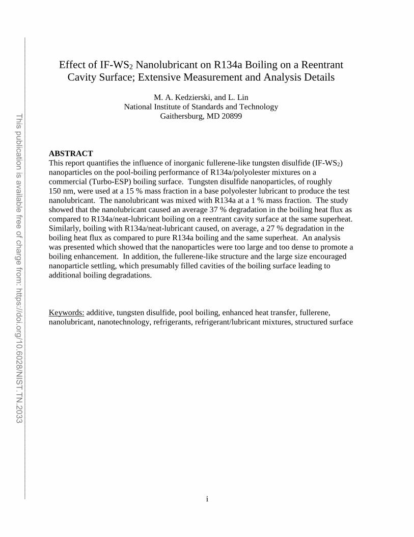
Table 2 Number of test days and data points Fluid (% mass fraction) Number of days
Number of data points
R134a
0.4 K ≤ ∆Ts ≤ 2.3 K 7 173
R134a/RL32 (99/1) 0.5 K ≤ ∆Ts ≤ 3.2 K
3 75
R134a/WS2 (99/1) 0.5 K ≤ ∆Ts ≤ 5.9 K
6 150
______________________________________________________________________________________________________ This publication is available free of charge from
: https://doi.org/10.6028/NIST.TN
.2033

16
Table 3 Estimated parameters for cubic boiling curve fits for Turbo-ESP copper surface ∆Ts = A0 + A1 q” + A2 q”2 + A3 q”3
∆Ts in kelvin and q” in W/m2 Fluid Ao A1 A2 A3 R134a
0.4 K ≤ ∆Ts ≤ 2.3 K
0. 1143419
2.084979x10⁻⁵
6.162379x10⁻¹¹
-3.848960x10⁻¹⁶
R134a/RL32 (99/1) 0.5 K ≤ ∆Ts ≤ 3.2 K
0.07866390
2.154077x10⁻⁵
3.999840x10⁻¹⁰
-2.812581x10⁻¹⁵
R134a/WS2 (99/1) 0.5 K ≤ ∆Ts ≤ 5.9 K
-0.1490710
4.111601x10⁻⁵
8.135857x10⁻¹⁰
-5.487150x10⁻¹⁵
______________________________________________________________________________________________________ This publication is available free of charge from
: https://doi.org/10.6028/NIST.TN
.2033
17
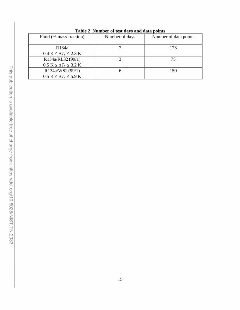
Table 4 Residual standard deviation of ∆Ts
Fluid (K) R134a
0.4 K ≤ ∆Ts ≤ 2.3 K
0.03 R134a/RL32 (99/1) 0.5 K ≤ ∆Ts ≤ 3.2 K
0.05
R134a/WS2 (99/1) 0.5 K ≤ ∆Ts ≤ 5.9 K
0.18
______________________________________________________________________________________________________ This publication is available free of charge from
: https://doi.org/10.6028/NIST.TN
.2033

18
Table 5 Average magnitude of 95 % multi-use confidence interval for mean ∆Ts Fluid U (K) R134a
0.4 K ≤ ∆Ts ≤ 2.3 K
0.02 R134a/RL32 (99/1) 0.5 K ≤ ∆Ts ≤ 3.2 K
0.04
R134a/WS2 (99/1) 0.5 K ≤ ∆Ts ≤ 5.9 K
0.10
______________________________________________________________________________________________________ This publication is available free of charge from
: https://doi.org/10.6028/NIST.TN
.2033

19
Fig. 1 Schematic of test apparatus.
______________________________________________________________________________________________________ This publication is available free of charge from
: https://doi.org/10.6028/NIST.TN
.2033

20
Fig. 2 OFHC copper flat test plate with the Turbo-ESP surface and thermocouple coordinate system.
______________________________________________________________________________________________________ This publication is available free of charge from
: https://doi.org/10.6028/NIST.TN
.2033

21
Fig. 3 Photograph of the Turbo-ESP surface.
______________________________________________________________________________________________________ This publication is available free of charge from
: https://doi.org/10.6028/NIST.TN
.2033

22
Fig. 4 R134a and R134a/RL32 (99/1) mixture boiling curves for the Turbo-ESP surface.
______________________________________________________________________________________________________ This publication is available free of charge from
: https://doi.org/10.6028/NIST.TN
.2033

23
Fig. 5 Boiling heat flux ratio of R134a/RL32 (99/1) the Turbo-ESP surface.
______________________________________________________________________________________________________ This publication is available free of charge from
: https://doi.org/10.6028/NIST.TN
.2033

24
Fig. 6 R134a/RL32 and R134a/nanolubricant mixtures boiling curves for the Turbo-ESP surface.
______________________________________________________________________________________________________ This publication is available free of charge from
: https://doi.org/10.6028/NIST.TN
.2033

25
Fig. 7 Boiling heat flux ratio of R134a/nanolubricant mixture for the Turbo-ESP surface.
______________________________________________________________________________________________________ This publication is available free of charge from
: https://doi.org/10.6028/NIST.TN
.2033

26
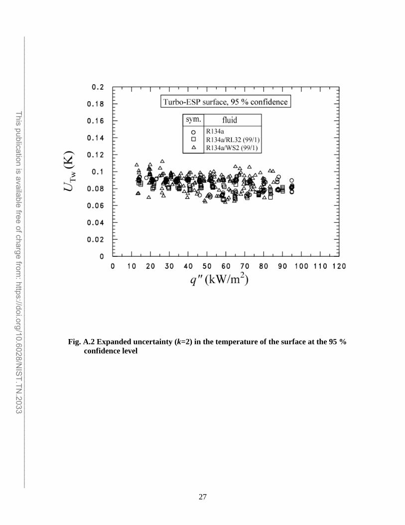
APPENDIX A: UNCERTAINTIES Figure A.1 shows the relative (percent) uncertainty of the heat flux (Uq") as a function of the heat flux. Figure A.2 shows the uncertainty of the wall temperature as a function of the heat flux. The uncertainties shown in Figs. A.1 and A.2 are “within-run uncertainties.” These do not include the uncertainties due to “between-run effects” or differences observed between tests taken on different days. The “within-run uncertainties” include only the random effects and uncertainties associated with one particular test. All other uncertainties reported in this study are “between-run uncertainties” which include all random effects such as surface past history or seeding.
Fig. A.1 Expanded relative uncertainty (k=2) in the heat flux of the surface at the 95 % confidence level.
______________________________________________________________________________________________________ This publication is available free of charge from
: https://doi.org/10.6028/NIST.TN
.2033
27
Fig. A.2 Expanded uncertainty (k=2) in the temperature of the surface at the 95 % confidence level
______________________________________________________________________________________________________ This publication is available free of charge from
: https://doi.org/10.6028/NIST.TN
.2033