Embed Size (px)
Citation preview

August 22, 2016 19:48 RPS 017
Effect of Hull Form and its Associated Parameters on the Resistance of a Catamaran
Zulkarnain Bin Ramsani*1, Ivan CK Tam*2, and Arun Dev*3
*School of Marine Science and Technology, Newcastle University
The total resistance of four different types of catamaran hull forms, which include the flat bottom, single chine, multi chine and the round bilge hull forms are presented and discussed in this paper. With the aid of Maxsurf software, the four catamaran hull forms were designed with the same principal dimensions, wetted surface area and the block coefficient. Maxsurf was then used to calculate the total resistance results of the four hull forms that lay in congruence to the displacement and semi-displacement speed range of Froude number (Fn) between 0.2 to 0.7. Also, three variations of the catamaran hull spacing parameter are also presented in this research to study the effect of an increasing separation to length ratio, S/L, on its total resistance. Discussions are made to evaluate for every result that was presented in this paper.
INTRODUCTION
Catamaran has become a popular choice among many passenger ferries, trawlers, and frigates as compared to the monohull. For example, the catamaran provides many benefits such as having a larger deck area and an excellent transverse stability due to its wider breadth. Moreover, the catamaran is also capable of providing a good rolling motion response in heavy seas.
The concept of a catamaran consists of two demi-hulls separated between a distance. Seemingly, the catamaran will experience a high frictional resistance due to having double the value of the wetted surface area as compared to a monohull. However, the large wetted surface area of a catamaran is not a major concern as it can usually be reduced by implementing a slender hull design. In fact, the frictional resistance component, which is typically dominant at low speeds, contribute a minor role in the total resistance of a catamaran, since the multihull vessel is mainly designed to operate at high speed. Hence, a significant contribution leading to an increase in the total resistance of a catamaran originated from the residuary resistance component, mainly the wave making resistance. The types of hull forms that are considered in the catamaran design stage and the varying separation distances set between the two demi-hulls can either provide a favourable or an adverse wave interaction effect, which, can have a various impact on the resistance results.
From the perspective of a naval architect, the importance of accurately understanding the effects on the types of catamaran hull forms and its hull spacing parameter can help to reduce the wave making resistance effectively. As a result, lowers the total resistance, enabling the ship owner to save on its fuel consumption and cost. Background and summary of conclusions from past research
Previous studies have shown that the wave making resistance of a catamaran can be improved by varying the separation to length ratio parameter, S/L, as illustrated in Fig. 1. A higher S/L ratio of up to 0.4 can provide a favourable wave interference effect between the Froude number of 0.35 to 0.42
Proc. of the 6th Intl. Conf. on Technology and Operation of Offshore Support Vessels (OSV Singapore 2016)Edited by Arun K Dev :: Copyright c© 2016 OSV Singapore 2016 Organizers.ISBN: 978-981-08-7921-1 :: Published by Research Publishing, Singapore. www.rpsonline.com.sg 56

August 22, 2016 19:48 RPS 017
Proc. of the 6th Intl. Conf. on Technology and Operation of Offshore Support Vessels 57
(Insel and Molland, 1992; Tasaki et al., 1963). However, studies on the use of a staggered hull catamaran have also shown to provide a better hydrodynamic behaviour on the wave resistance (Sahoo et al., 2006; Soeding et al., 1997).
Cirellio et al. (2013) and Zaraphoniti et al. (2001) have previously conducted the study of an asymmetrical catamaran hull shape between the Flat Side Inside (FSI) and the Flat Side Outside (FSO) hull configurations. Results showed that the FSO hull tends to generate a stronger wave interaction effects as compared to the FSI hull. Moreover, Utama et al. (2012) and Setyawan et al. (2010) have presented a study in comparing between the symmetrical and asymmetrical hull of a catamaran, and it was reported that the latter obtained a reduced number of in-phase wave systems generated between the two demi-hulls.
On the other hand, Iqbal and Trimulyono (2014) have shown how the resistance of a catamaran can be improved by optimizing the .
Besides, studies on the resistance concerning the hard chine and the round bilge monohull form have also been presented. It can be learnt that the round bilge hull form exhibits a lower resistance between displacement to semi-displacement speed whereas the hard chine hull form is capable of providing favourable resistance results at planing speed. However, since the experiment was conducted based on a monohull form, hence, it does not take into account of the viscous and wave interaction factors attributed to the multihull forms (Armstrong and Clarke, 2009; Blount, 1995; Razenback and Bowles, 2010).\
Fig. 1. Catamaran configuration indicating the S/L ratio
Aims and objectives
The aims and objectives of this research is to Provide a comparison study on the total resistance of the four different types of symmetrical
catamaran hull forms which include the flat bottom, single chine, multi chine and round bilge hull forms.
Analyse the resistance of the four hull forms at displacement speed range (Fn < 0.4) and semi-displacement speed range (Fn > 0.4).
Investigate the effect of an increasing S/L ratio on the resistance of the four catamaran hull forms and provide an example of a free surface wave pattern analysis.
METHODOLOGY Four types of catamaran hull forms were designed using the Maxsurf Modeler software. These hull forms, as shown from Fig. 2, include from a flat bottom, single chine, multi (double) chine and round bilge hull forms.
August 22, 2016 19:48 RPS 017
58 Arun Kr Dev (Eds.)
Fig. 2. Four types of catamaran hull forms designed using Maxsurf software.
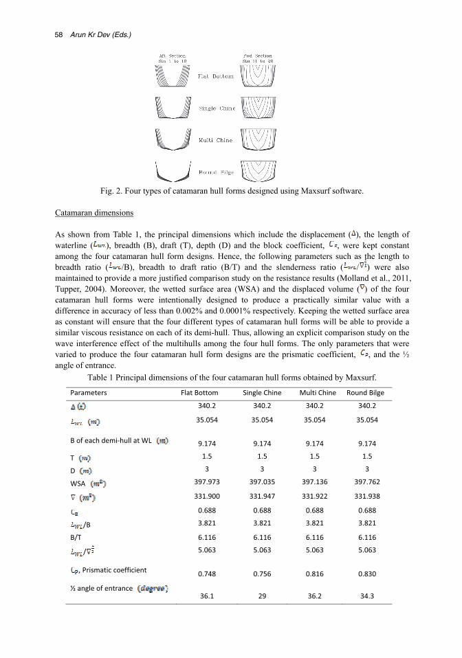
Catamaran dimensions As shown from Table 1, the principal dimensions which include the displacement ( ), the length of waterline ( ), breadth (B), draft (T), depth (D) and the block coefficient, , were kept constant among the four catamaran hull form designs. Hence, the following parameters such as the length to breadth ratio ( /B), breadth to draft ratio (B/T) and the slenderness ratio ( / ) were also maintained to provide a more justified comparison study on the resistance results (Molland et al., 2011, Tupper, 2004). Moreover, the wetted surface area (WSA) and the displaced volume ( ) of the four catamaran hull forms were intentionally designed to produce a practically similar value with a difference in accuracy of less than 0.002% and 0.0001% respectively. Keeping the wetted surface area as constant will ensure that the four different types of catamaran hull forms will be able to provide a similar viscous resistance on each of its demi-hull. Thus, allowing an explicit comparison study on the wave interference effect of the multihulls among the four hull forms. The only parameters that were varied to produce the four catamaran hull form designs are the prismatic coefficient, , and the ½ angle of entrance.
Table 1 Principal dimensions of the four catamaran hull forms obtained by Maxsurf.
Parameters Flat Bottom Single Chine Multi Chine Round Bilge
340.2 340.2 340.2 340.2
35.054 35.054 35.054 35.054
B of each demi hull at WL 9.174 9.174 9.174 9.174
T 1.5 1.5 1.5 1.5
D 3 3 3 3
WSA 397.973 397.035 397.136 397.762
331.900 331.947 331.922 331.938
0.688 0.688 0.688 0.688
/B 3.821 3.821 3.821 3.821
B/T 6.116 6.116 6.116 6.116
/ 5.063 5.063 5.063 5.063
, Prismatic coefficient 0.748 0.756 0.816 0.830
½ angle of entrance36.1 29 36.2 34.3

August 22, 2016 19:48 RPS 017
Proc. of the 6th Intl. Conf. on Technology and Operation of Offshore Support Vessels 59
As shown from Table 2, three sets of catamaran hull spacing have been varied in this experiment for each of the four hull forms to provide a study on the effect of an increasing S/L ratio in the catamaran resistance. The separation distance, S, measured between the centre line of demi-hull to the centre line of the catamaran was varied at an interval of 7.5m, 11m, and 14.5m.
Table 2 S/L ratio variation.
S = 7.5 S = 11 S = 14.5
S/L 0.214 0.314 0.414
Design process considerations The designs of the four hull forms were generated by Maxsurf based on varying the control points which are divided between the number of columns and rows, as shown from Fig. 3 and Fig. 4. The surface of the demi-hull shape is defined by the position of the control points. The location of each control point was varied by having to input the numerical values to its longitudinal, height and offset position to obtain the required four hull form designs. The four hull forms were created based on twenty stations, three buttock lines, and five waterlines.
Fig. 3 Plan view of multi chine demi-hull representing columns of control points.
Fig. 4 Body plan view of multi chine demi-hull representing rows of control points.
The flat bottom hull was generated to obtain a flat keel from the forward section to the stern by adjusting the height of its bottom control points to the baseline, and it obtained with the lowest , where most of its displacement is moved near the amidships, resulting in a narrow after body section.
As for the single chine and multi chine hull forms, additional rows of control points were added in the body plan view. The process of compacting and grouping two rows of control points in each column allowed an individual chine to be formed along the length of the catamaran hull, as shown from Fig. 5 and Fig. 6. The single chine hull form was designed with a shallow deadrise angle and as a result, it obtained the lowest ½ angle of entrance among the four catamaran hull forms. Whereas the multi chine hull form was able to design with a slightly deeper deadrise angle, and it obtained the highest ½ angle of entrance.
Fig. 5 Before compacting and grouping two control points.

August 22, 2016 19:48 RPS 017
60 Arun Kr Dev (Eds.)
Fig. 6 After compacting and grouping two control points to form a single chine.
Lastly, the round bilge hull form has been developed based on achieving a smooth curvature at the bilge of the hull along its length, and it obtained with the largest , where most of its displacement located at the hull ends. Sectional area curve
As shown from Fig. 7, the design of the four catamaran hull forms has been generated with a difference in the slope entrance of its sectional area curve. The design of the single chine hull form was obtained with a gradual slope at the bow of the sectional area curve, whereas the design of the round bilge, multi chine, and the flat bottom hull forms produced a slightly steeper slope entrance.
Fig. 7 Fwd sectional area curve from amidships.
Method of resistance calculation for catamaran The resistance of the four hull forms was calculated based on the slender body method with the aid of the Maxsurf Resistance software by using the technique proposed by Insel and Molland (1992), which takes into account of the hull interaction effects attributed by the multihulls. The slender body method uses the first principle approach from the potential flow calculation. This method is suitable for application of slender hulls with a typical range of slenderness ratio between 5.0 to 6.0, which complement well with the design of the four catamaran hull forms.
The following formula in equation (1) proposed by Insel and Molland (1992) describes the method of calculating the total resistance of a catamaran. The total resistance coefficient of a catamaran, , can be obtained through calculating the frictional resistance coefficient, and the wave resistance coefficient, , for two isolated demi-hulls. Besides, two interference factors are required to be taken into account in calculating the total resistance coefficient of a catamaran; these are the viscous interference factor, and the wave interference factor, . The viscous interference factor, , is obtained by the combination of changes in the pressure field, , measured around the demi-hull and the velocity augmentation, , measured between the two demi-hulls. Lastly, the wave interference factor, is obtained from the wave interaction systems generated for each demi-hull.
WFT CCkC )1( (1)
where = total resistance coefficient of a catamaran; = frictional resistance coefficient based on ITTC 1957 correlation line; = wave resistance coefficient for an isolated demi-hull; = form factor for an isolated demi-hull; = changes in the pressure field around the demi-hull; = velocity augmentation between two demi-hulls and = wave interference factor.

August 22, 2016 19:48 RPS 017
Proc. of the 6th Intl. Conf. on Technology and Operation of Offshore Support Vessels 61
The and can be combined to form a viscous interference factor, , to suit the practical purpose of the experiment as shown from equation (2).
WFT CCkC )1( (2) Slender body analysis geometry
The mesh series implemented by Maxsurf is symmetrical about the centre line of an individual demi-hull as shown from Fig. 8. The size of the mesh used in this experiment for the four types of catamaran hull forms was increased from default 81 contours to 201 contours. The primary objective of using a higher number of mesh contours is to provide a greater accuracy on the resistance prediction of the catamaran.
Fig. 8. Round bilge hull with a mesh size of 201 number of contours, symmetrical about the demi-hull.
RESULTS AND DISCUSSIONS Frictional resistance of the catamaran demi-hull
As shown from Fig. 9, the demi-hull of the four different types of catamaran hull form have obtained the same frictional resistance results, between the range of Froude number, Fn = 0.2 to 0.7. This objective has been achieved by having to design the four various hull forms with a practically similar wetted surface area. The impression is to allow a justified comparison study among the four different types of catamaran hull forms on its wave interference effect, which is a significant contribution to its resistance.
It can also be noted from Fig. 9 that a substantial increase in the frictional resistance of the four catamaran hull forms dominates at low Fn. As the speed increases further, the total resistance coefficient, of the four catamaran hull forms began to decrease correspondingly.
Fig. 9. Catamaran demi-hull frictional resistance.
Effect of hull forms on the catamaran resistance at three various S/L ratios It can be observed from Figs. 10 - 12 that at the region of displacement speed (0.2 < Fn < 0.43), generally all the four hull forms experienced an irregular wave interference effect with large number of

August 22, 2016 19:48 RPS 017
62 Arun Kr Dev (Eds.)
pronounced humps and troughs, indicating a strong influence of the transverse waves. Within the displacement speed range, the wave interference effect of the four catamaran hull forms is mainly dependent on the Fn. The Fn at which a favourable wave interference effect can be obtained within the displacement speed range varies with the types of hull forms. Hence, to produce an efficient catamaran design that is required to operate within the displacement speed range, the choice of its service speed for the various types of catamaran hull forms must be prudently selected in the region whereby an adverse wave interference effect can be avoided, resulting in a lower resistance.
Figs. 10 - 12 also displayed that the single chine hull form experienced the least resistance among the four hull forms (0.2 < Fn < 0.7) whereas the multi chine hull form exhibited the highest resistance within the displacement speed range (0.2 < Fn < 0.35). Since the single chine hull form was designed with the lowest ½ angle of entrance = 29° and a gradual slope entrance of its sectional area curve, hence, it exhibits a reduced pressure around its bow stagnation point. As a result, it generates a lower wave height at the bow, leading to a lower wave making resistance. Furthermore, this can signify that the single chine hull form experienced a more favourable wave system as compared to the multi chine hull form, which was designed with a highest ½ angle of entrance = 32°. Hence, it can be implied that the wave making resistance of the four catamaran hull forms within the displacement speed range are dominated by the shape of its waterline entrance. In obtaining a lower resistance within the displacement speed range, the catamaran hull form should be designed with a low waterline angle of entrance and a sharper bow by reducing the slope entrance of the sectional area curve.
With reference from Figs. 10 - 12, as the Fn increases beyond 0.43, towards the semi-displacement speed range, the length of the four catamaran hull forms experienced an equal length to the transverse wave. As a result, all the four hull forms exhibited a steady increase in the total resistance. The resistance of the four catamaran hull forms is increased further until it reached to a hump, between the Fn of 0.48 to 0.5. At this range of Fn, the waves generated by the four hull forms are considered long; hence, it responds to a longer component of the free surface pressure distribution (Larsson et al., 2010). As a result, the wave making resistance of the four hull forms within the semi-displacement speed range is now dependent on its sectional area curve. Hence, the flat bottom hull form, which was designed with the lowest of 0.748 and a narrow after body section, experienced the highest resistance among all the four hull forms at all three S/L ratios. Indicating a stronger wave interference effects that contributed to an unfavourable wave system generated between the two demi-hulls. The design of a higher obtained by the multi chine and the round bilge hull forms exhibited a lower resistance than the flat bottom hull form. Hence, to avoid a high resistance within the semi-displacement speed range, the catamaran hull form should be designed with a higher and a smaller mid-body area by distributing most of its displacement at the hull ends. Since a higher is capable of providing an additional buoyancy on the hulls ends at high Fn, which improves the bow and stern wave systems towards achieving a favourable wave interaction system and a lower wave making resistance.
Fig. 10 Catamaran total resistance at S/L = 0.214.

August 22, 2016 19:48 RPS 017
Proc. of the 6th Intl. Conf. on Technology and Operation of Offshore Support Vessels 63
Fig. 11 Catamaran total resistance at S/L = 0.314. Fig. 12 Catamaran total resistance at S/L = 0.414. Effect of an increasing S/L ratio on the catamaran resistance Based on Figs. 13 - 16, it can be observed that the effect of an increasing S/L ratio within the displacement speed range (Fn < 0.43) in providing a beneficial resistance on the four catamaran hull forms is limited to a small range of Froude number. Rather, the S/L ratio is largely dependent on the Froude number. It can be noted from Figs. 13 - 15 that as the S/L ratio increases from 0.214 to 0.414, the flat bottom, single chine and the multi chine hull forms experienced a decrease towards a lower resistance at the limited speed range between the Fn of 0.3 to 0.35. Similarly, with reference to Fig. 16, the round bilge hull form experienced a reduction in its total resistance at the limited speed range between the Fn of 0.32 to 0.36. Hence, for a catamaran that is designed to operate between the displacement speed range, having a large hull spacing to obtain a lower resistance may not be an ideal solution towards an effective design. Instead, selecting a favourable speed to operate within the displacement speed range is a much better approach.
However, at the semi-displacement speed range (Fn > 0.43), the benefit of an increasing S/L ratio in achieving a lower catamaran resistance displayed a more pronounced effect. It can be noted from Figs. 13 - 15 that with an increasing of the S/L ratio from 0.214 to 0.414, the resistance of the flat bottom, single chine and the multi chine hull forms began to decrease correspondingly beyond the Fn of 0.43. Similarly, the round bilge hull form experienced a consistent decrease in its resistance at the semi-displacement speed range beyond the Fn of 0.48, as shown from Fig. 16. Hence, for a catamaran design that is required to operate between the semi-displacement speed range, increasing its hull spacing will be an ideal solution to provide a beneficial reduction in its resistance.
In general, the results of the four hull forms have shown that the benefit effect of increasing the catamaran hull spacing in achieving a lower resistance can be obtained at two different sets of the speed range. Consisting of the displacement speed range (0.32 < Fn < 0.36) and at the semi-displacement speed range (Fn > 0.48). It can be understood that between these two sets of Froude number range, improvements towards a favourable wave interference effect can be observed between the two demi-hulls along with an increasing S/L ratio.
Fig. 13 Flat bottom hull at various S/L ratios. Fig. 14 Flat bottom hull at various S/L ratios.

August 22, 2016 19:48 RPS 017
64 Arun Kr Dev (Eds.)
Fig. 15 Multi chine hull at various S/L ratios. Fig. 16 Round bilge hull at various S/L ratios.
Free surface wave pattern analysis Alternatively, the effect of increasing the catamaran S/L ratio on the wave interference between the two demi-hulls can be illustrated by observing the contours plots of the wave pattern as shown from Fig. 17 and Fig. 18. It can be seen from Fig. 17 that at the semi-displacement speed of Fn = 0.527, a significant number of prominent concentrated red, blue and purple contours indicating greater wave height generated by the multi chine hull can be observed at S/L = 0.214, signifying a complex wave pattern. As the S/L ratio increases further to 0.414, the large concentrated red, blue and purple contours began to spread out and weakened, indicating a lower wave energy being produced by the hulls resulting in a reduced wave making resistance, as shown from Fig.18.
Fig. 17 Wave pattern of multi chine hull Fig. 18 Wave pattern of multi chine hull at Fn = 0.527, S/L = 0.214. at Fn = 0.527, S/L = 0.414. CONCLUDING REMARKS In this paper, the hydroelastic problem for a circular VLFS subjected to wave is analyzed in an exact manner for both plate and fluid parts. The implementations if the method presented herein is not so complicated for engineers to obtain accurate solutions for their hydroelastic analysis. Most importantly, the theory used here is based on the more refined Mindlin plate theory, instead of the commonly used classical thin plate theory. With this advanced feature, we can obtain exact stress resultants that satisfy free-edge boundary conditions.
In summary, four different types of catamaran hull forms were designed with constant principal dimensions, wetted surface area and , to provide an explicit comparison study on the resistance. The four hull forms include the flat bottom, single chine, multi chine and the round bilge. Three variations of catamaran S/L ratio which consists of 0.214, 0.314 and 0.414 were also introduced to the four hull forms to investigate the effect of an increasing hull spacing on its resistance. Hence, the following conclusions can be drawn:

August 22, 2016 19:48 RPS 017
Proc. of the 6th Intl. Conf. on Technology and Operation of Offshore Support Vessels 65
At the displacement speed range of low Fn, the design of a large ½ angle of entrance and a steep slope of the sectional area curve at the bow contributed to a higher resistance. Whereas at the semi-displacement speed range of high Fn, the design of a low prismatic coefficient, lead to a large increase in the resistance.
Among the four catamaran hull forms that were designed in this research, the single chine catamaran hull form produced the least resistance throughout the range of displacement and semi-displacement speeds between the Fn of 0.2 to 0.7, at all three S/L ratios of 0.214, 0.314 and 0.414. The optimum design parameter of the ½ angle of entrance = 29° and = 0.756 obtained by the single chine hull form have contributed to a more favourable wave interference effect.
The lowest design of 0.748 and a narrow after body section obtained by the flat bottom
hull form resulted in a large increase in the resistance at semi-displacement speed range.
The effect of an increasing S/L ratio at the displacement speed range in providing a beneficial catamaran resistance is mainly erratic. The S/L ratio is largely dependent on the Fn value.
The effect of an increasing S/L ratio at the semi-displacement speed range in providing a beneficial catamaran resistance is consistent and gradual.
The increment of the S/L ratio from 0.214 to 0.414 displayed a beneficial reduction in the
resistance of the four hull forms at the displacement speed between the limited range of Fn = 0.3 to 0.36, and the semi-displacement speed range beyond the Fn > 0.48.
Recommendations The following possible approaches can be conveyed in expanding the knowledge of this subject in demonstrating the future direction of this research. Designing a low ½ angle of waterline entrance for a particular catamaran hull form could provide a beneficial wave system in terms of reducing the elevated pressure at the bow wave. However, selecting its optimum , for a given specific operating speed is crucial as well in achieving a lower wave making resistance. Hence, to obtain an optimum , for a particular type of catamaran hull form and its operating speed, the Lackenby method can be proposed by varying its mid-sectional area. Obtaining an optimum S/L ratio that fits for all types of catamaran hull forms may not be possible. The wave interaction effects which is due to the asymmetric pressure field and its velocity augmentation between the two demi-hulls may cause the catamaran viscous form factor to vary with different types of hull forms. Moreover, the interaction between the waves of the two demi-hulls can result in a complicated divergent wave system which varies with different types of hull forms. Hence, it is required to develop an iteration process in experimenting an appropriate hull spacing for a particular catamaran hull form during the design stage, which will aid in changing the wave making of the two demi-hulls to obtain a favourable wave interference effect. As for the single chine and multi chine hull forms, improvements towards in obtaining a more beneficial resistance and propulsive efficiency can be achieved by varying the height of its chine placement. Optimizing the height of the chine may result in improvements on the wave interference system and its wake flow.
August 22, 2016 19:48 RPS 017
66 Arun Kr Dev (Eds.)
ACKNOWLEDGEMENTS The first authors would like to their appreciation to Newcastle University (Singapore) in the support of this research work. REFERENCES Armstrong, T. and Clarke, T., 2009. On the effect of hull shape on the performance of existing high
speed ferries. In: 10th International Conference on Fast Sea Transportation. Athens: FAST, p.12. Blount, D.L., 1995. Factors Influencing the Selection of Hard Chine or Round Bilge hull for high
Froude Numbers. In: Fast Sea Transportation International Conference. Lubeck: FAST, pp.3-20. Cirello, A., Damiano, C., Lupo, G., Mancuso, A. and Mariotti, G.V., 2013. CFD Study of an
Innovative Catamaran with Asymmetrical Hulls. Advances in Water Resource and Protection, 1(1), p.10.
Insel, M., and Molland, A. F., 1992. An investigation into the resistance components of high speed displacement catamarans. Royal Institution of Naval Architects Transactions, 134, p.20.
Iqbal, M. and Trimulyono, A., 2014. Optimization of catamaran demi hull form in early stages of the design process. Kapal, 11(3), pp.126-131.
Larsson, L., Raven, H. and Paulling, J., 2010. Ship resistance and flow. Jersey City, N.J.: Society of Naval Architects and Marine Engineers, pp.31-196.
Molland, A., Turnock, S. and Hudson, D., 2011. Ship resistance and propulsion. New York: Cambridge University Press, pp.29-228.
Ranzenback, R. and Bowles, J., 2010. Hull forms with low cruise speed resistance and high speed dynamic stability. In: Proceedings of the 29th American Towing Tank Conference. Annapolis: ATTC, pp.251-259.
Sahoo, P. L., Doctors, L. K., Luke, P., 2006. CFD Prediction of the Wave Resistance of a Catamaran with Staggered demi hulls. In: International Conference on Marine Hydrodynamics. Visakhapatnam: MAHY, p.10.
Setyawan, D., Utama, I.K., Murdijanto, M., Sugiarso, A. and Jamaluddin, A., 2010. Development of Catamaaran Fishing Vessel. IPTEK The Journal for Technology and Science, 21(4), pp.167-173.
Soeding, H., 1997. Drastic resistance reduction in catamarans by staggered hulls. In: Fourth International Conference on Fast Sea Transportation. Sydney: FAST97, pp.225-230.
Tasaki, R., Takahei, T. and Moss, J., 1963. Wave-making resistance interference effects on a catamaran model. Ann Arbor: University of Michigan College of Engineering, pp.1-14.
Tupper, E., 2004. Introduction to naval architecture. Amsterdam: Elsevier, Butterworth Heinemann, pp.154-160.
Utama, I. K., Jamaluddin, A. and Aryawan, W.D., 2012. Experimental Investigation into the drag interference. Technology to the wind, 7(1), pp.46-58.
Zaraphoniti, G., Spanos, D. and Papanikolaou, A., 2001. Numerical and Experimental Study on the Wave resistance of Fast Displacement Asymmetric Catamarans. In: The 2nd International Euro-Conference on High-Performance Marine Vehicles. Hamburg: HIPER, p.13.