Embed Size (px)
Citation preview
International Journal of Scientific & Engineering Research, Volume 5, Issue 7, July-2014 1532 ISSN 2229-5518
IJSER © 2014 http://www.ijser.org
Effect of heat input on microstructure and mechanical properties of the TIG
welded joints of AISI 304 stainless steel
T.A.Tabish*,1 T.Abbas*, M.Farhan*, S.Atiq*, T.Z.Butt**
Abstract:
AISI 304 stainless steel plates were butt-welded through manual tungsten inert gas
welding (TIG) process. The process was applied to different specimens by varying heat inputs
(low, medium and high). The microstructural features and mechanical properties of the welded
joints were examined. The results showed that the tensile strength of welded specimens was
greater than that of the base metal. Maximum tensile strength was possessed by the specimen
welded using low heat input and vice versa. Microhardness measurements implied that hardness
near the upper surface of the weld is high and that near the center of the weld is low because of
the faster cooling of the exterior than the interior of the weld. Microhardness increased from 205
VHN to 230 VHN for low heat input, 194 VHN to 211 VHN for medium heat input, and 182
VHN to 195 VHN for high heat input welded specimens. The microstructural study indicated
that the high heat input produced larger dendrites than those produced with medium, and low
heat input.
Keywords:
Tungsten inert gas are welding, Microstructure, Micro hardness, Tensile Test
Introduction:
Excellent mechanical properties of
austenitic stainless steels made them an
important structural material for nuclear
plants. Consequently, reactor coolant piping,
valve bodies and vessel internals have been
manufactured from these steels. However,
IJSER
International Journal of Scientific & Engineering Research, Volume 5, Issue 7, July-2014 1533 ISSN 2229-5518
IJSER © 2014 http://www.ijser.org
welding frequently leads to poor mechanical
properties of the weldment due to the
metallurgical changes associated with fusion
welding processes such as segregation,
precipitation of secondary phases, presence
of porosities, solidification cracking and
grain growth in the heat affected zone
(HAZ) etc. [1]. Type 300 series of austenitic
stainless steels contain considerable amounts
of chromium and nickel; the former provides
corrosion resistance and the latter stability of
austenite phase at room temperature. The
basic composition of traditional austenitic
stainless steel includes 18% chromium and
8% nickel, but can also include small
proportions of molybdenum, titanium,
niobium, copper and nitrogen. Other useful
properties of engineering significance such
as excellent corrosion resistance, superior
creep rupture strength and impact resistance
at low temperatures make austenitic
stainless steels a competitive choice for
industrial plants encompassing applications
in chemical processing, food production,
marine hardware, furnaces, heat exchangers,
gas turbines, and cryogenic vessels.
To fabricate stainless steel structures,
welding is generally the most convenient
process. But the common arc welding results
in coarse grains and carbides formation
along the grain boundaries in HAZ. Both the
coarser structure and carbides, which are
rich in chromium, deteriorate the mechanical
properties of the weldment [2,3]. Therefore,
type 300 series is often joined through gas
tungsten arc welding (GTAW), also known
as tungsten inert gas (TIG) welding,
essentially consisting of production of an arc
between a non-consumable tungsten
electrode and the work piece. An inert gas,
usually argon, protects the arc, electrode and
molten pool from atmospheric
contamination. While joining the thinner
surfaces, edge joints and flanges, filler
metals are generally not required. However,
for thicker cross-sections, a filler metal is
needed to feed the joint. TIG welding is
equally capable of joining thin as well as
thick materials to achieve quality welds for
materials ranging from stainless steels to
non-ferrous alloys. TIG welding has some
limitations as compared to gas metal arc
welding (GMAW), major being inferior
joint penetration and poor tolerance to many
material compositions [4,5]. However,
penetrating ability of activated TIG arc can
markedly be improved by applying fluxes,
generally composed of oxides of Mn, Mo,
Ti, Si and Al, on surfaces prior to welding [6
– 8]. However, the primary drawback of
TIG welding process is its inability to join
thicker surfaces in a single pass. For butt-
IJSER
International Journal of Scientific & Engineering Research, Volume 5, Issue 7, July-2014 1534 ISSN 2229-5518
IJSER © 2014 http://www.ijser.org
joint penetration, multi-pass technique must
be used when thickness of stainless steel
plates to be joined exceeds 3mm [2,8]. The
laser-TIG hybrid welding overcomes these
limitations allowing improved welding
stability and greater melting efficiency [1].
In preceding studies, joints made
from the TIG welding process have not been
examined in detail with reference to
microhardness varying across the joint. The
present work expatiates the TIG joints of
AISI 304 stainless steel plates through
microstructural observations and mechanical
properties.
Materials and Experimental Procedures:
AISI 304 stainless steel plates of
sizes 200mm x 100mm x 6mm cut from a
rolled sheet and the filler 308 stainless steel
solid electrode EW-Th-2 (thoriated
tungsten) of 3.15 mm diameter were utilized
for this study. The measured compositions
of base and filler materials are given in
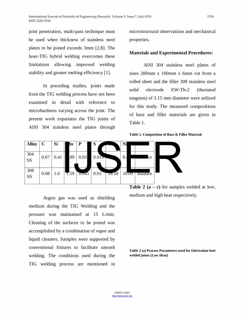
Table 1.
Table 1. Composition of Base & Filler Material
Alloy C Si Mn P S Cr Ni Fe
304 SS
0.07 0.41 1.89 0.03 0.015 18.6 8.48 Balance
308 SS 0.08 1.0 1.59 0.045 0.03 18.10 10.09 Balance
Argon gas was used as shielding
medium during the TIG Welding and the
pressure was maintained at 15 L/min.
Cleaning of the surfaces to be joined was
accomplished by a combination of vapor and
liquid cleaners. Samples were supported by
conventional fixtures to facilitate smooth
welding. The conditions used during the
TIG welding process are mentioned in
Table 2 (a – c) for samples welded at low,
medium and high heat respectively.
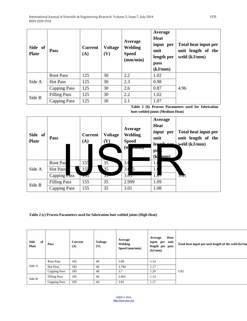
Table 2 (a) Process Parameters used for fabrication butt welded joints (Low Heat)
IJSER
International Journal of Scientific & Engineering Research, Volume 5, Issue 7, July-2014 1535 ISSN 2229-5518
IJSER © 2014 http://www.ijser.org
Side of Plate
Pass Current (A)
Voltage (V)
Average Welding Speed (mm/min)
Average Heat input per unit length per pass (kJ/mm)
Total heat input per unit length of the weld (kJ/mm)
Side A Root Pass 125 30 2.2 1.02
4.96
Hot Pass 125 30 2.3 0.98 Capping Pass 125 30 2.6 0.87
Side B Filling Pass 125 30 2.2 1.02 Capping Pass 125 30 2.1 1.07
Table 2 (b) Process Parameters used for fabrication butt welded joints (Medium Heat)
Side of Plate
Pass Current (A)
Voltage (V)
Average Welding Speed (mm/min)
Average Heat input per unit length per pass (kJ/mm)
Total heat input per unit length of the weld (kJ/mm)
Side A Root Pass 155 35 3.01 1.08
5.41
Hot Pass 155 35 3.005 1.08 Capping Pass 155 35 3.03 1.07
Side B Filling Pass 155 35 2.999 1.09 Capping Pass 155 35 3.01 1.08
Table 2 (c) Process Parameters used for fabrication butt welded joints (High Heat)
Side of Plate
Pass Current (A)
Voltage (V)
Average Welding Speed (mm/min)
Average Heat input per unit length per pass (kJ/mm)
Total heat input per unit length of the weld (kJ/mm
Side A Root Pass 185 40 3.88 1.14
5.82
Hot Pass 185 40 3.784 1.17 Capping Pass 185 40 3.7 1.20
Side B Filling Pass 185 40 3.901 1.14
Capping Pass 185 40 3.81 1.17
IJSER
International Journal of Scientific & Engineering Research, Volume 5, Issue 7, July-2014 1536 ISSN 2229-5518
IJSER © 2014 http://www.ijser.org
The specimens used for tensile
testing, microstructure study, and micro-
hardness testing were sectioned, cleaned,
grounded, polished and electrolytically
etched. An electrolytic oxalic acid (10g)
with distilled water (100mL) supplied with a
cell voltage of 6 V with etching time of 1
min was provided for electrolytic etching of
the sample. The microstructure was finally
examined by optical microscope (METKON
IMM901). The specimens were tested on a
computerized tensile testing machine of
100KN capacity with very slow strain rates
(ɛ=10-4 to 10-2 s-1). Hardness distribution at
transverse and longitudinal axis on the joints
was measured using a Vickers hardness
tester (FM-800) with testing load and
holding time of 1 kg and 15 s respectively.
Results & Discussions:
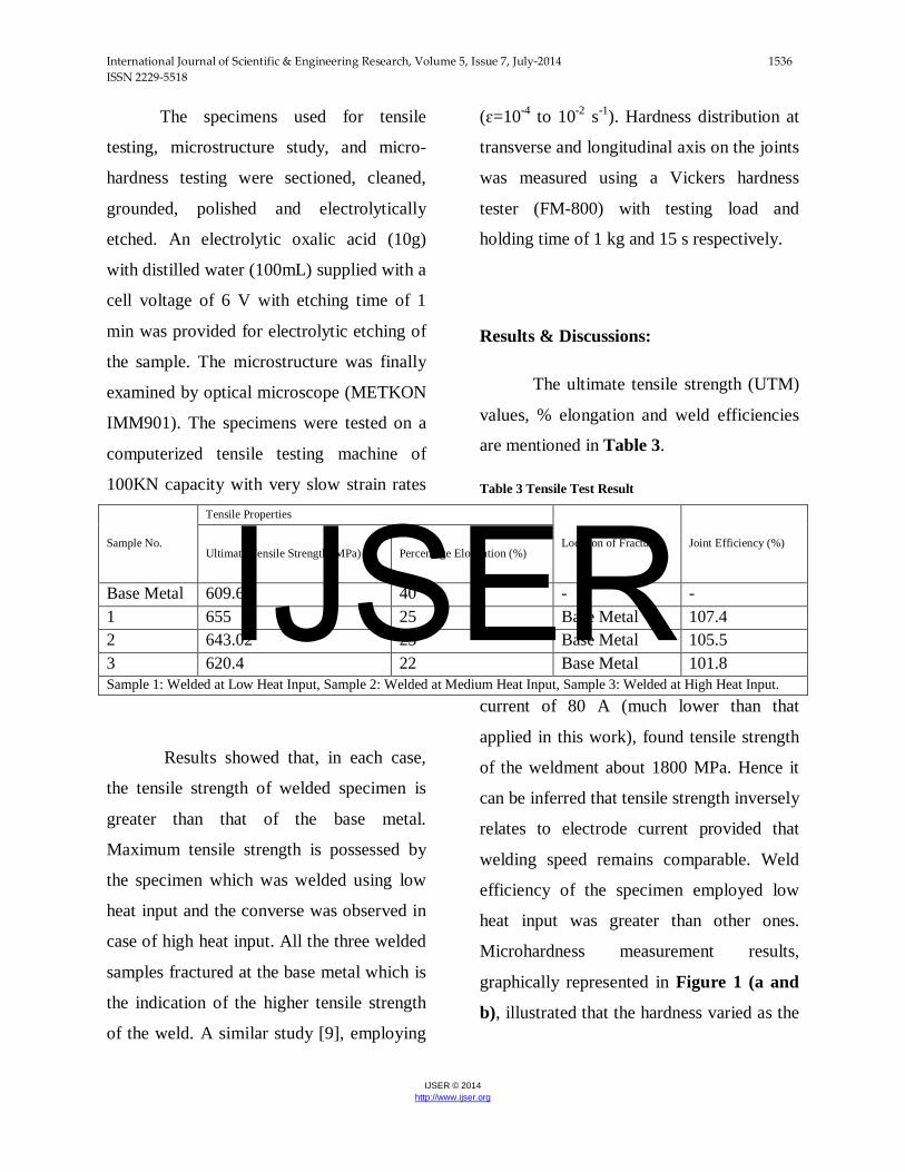
The ultimate tensile strength (UTM)
values, % elongation and weld efficiencies
are mentioned in Table 3.
Table 3 Tensile Test Result
Sample No.
Tensile Properties
Location of Fracture Joint Efficiency (%) Ultimate Tensile Strength (MPa) Percentage Elongation (%)
Base Metal 609.68 40 - - 1 655 25 Base Metal 107.4 2 643.02 23 Base Metal 105.5 3 620.4 22 Base Metal 101.8 Sample 1: Welded at Low Heat Input, Sample 2: Welded at Medium Heat Input, Sample 3: Welded at High Heat Input.
Results showed that, in each case,
the tensile strength of welded specimen is
greater than that of the base metal.
Maximum tensile strength is possessed by
the specimen which was welded using low
heat input and the converse was observed in
case of high heat input. All the three welded
samples fractured at the base metal which is
the indication of the higher tensile strength
of the weld. A similar study [9], employing
current of 80 A (much lower than that
applied in this work), found tensile strength
of the weldment about 1800 MPa. Hence it
can be inferred that tensile strength inversely
relates to electrode current provided that
welding speed remains comparable. Weld
efficiency of the specimen employed low
heat input was greater than other ones.
Microhardness measurement results,
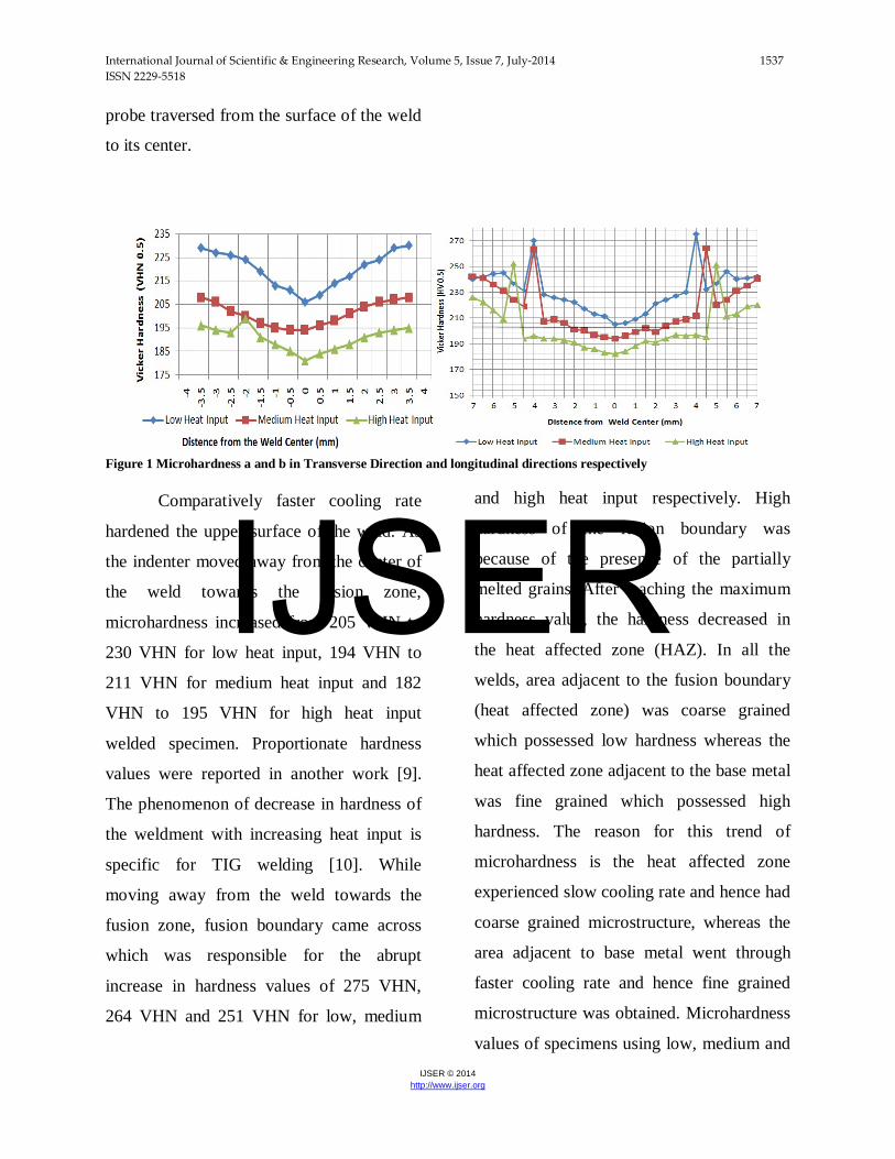
graphically represented in Figure 1 (a and
b), illustrated that the hardness varied as the
IJSER
International Journal of Scientific & Engineering Research, Volume 5, Issue 7, July-2014 1537 ISSN 2229-5518
IJSER © 2014 http://www.ijser.org
probe traversed from the surface of the weld
to its center.
Figure 1 Microhardness a and b in Transverse Direction and longitudinal directions respectively
Comparatively faster cooling rate
hardened the upper surface of the weld. As
the indenter moved away from the center of
the weld towards the fusion zone,
microhardness increased from 205 VHN to
230 VHN for low heat input, 194 VHN to
211 VHN for medium heat input and 182
VHN to 195 VHN for high heat input
welded specimen. Proportionate hardness
values were reported in another work [9].
The phenomenon of decrease in hardness of
the weldment with increasing heat input is
specific for TIG welding [10]. While
moving away from the weld towards the
fusion zone, fusion boundary came across
which was responsible for the abrupt
increase in hardness values of 275 VHN,
264 VHN and 251 VHN for low, medium
and high heat input respectively. High
hardness of the fusion boundary was
because of the presence of the partially
melted grains. After reaching the maximum
hardness value, the hardness decreased in
the heat affected zone (HAZ). In all the
welds, area adjacent to the fusion boundary
(heat affected zone) was coarse grained
which possessed low hardness whereas the
heat affected zone adjacent to the base metal
was fine grained which possessed high
hardness. The reason for this trend of
microhardness is the heat affected zone
experienced slow cooling rate and hence had
coarse grained microstructure, whereas the
area adjacent to base metal went through
faster cooling rate and hence fine grained
microstructure was obtained. Microhardness
values of specimens using low, medium and
IJSER
International Journal of Scientific & Engineering Research, Volume 5, Issue 7, July-2014 1538 ISSN 2229-5518
IJSER © 2014 http://www.ijser.org
high heat input are given in Table 4 (a and
b) respectively.
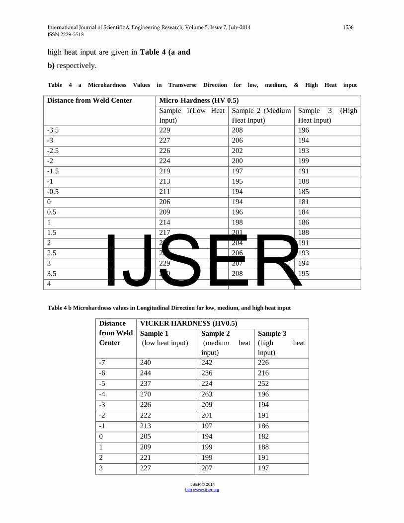
Table 4 a Microhardness Values in Transverse Direction for low, medium, & High Heat input
Distance from Weld Center Micro-Hardness (HV 0.5) Sample 1(Low Heat Input)
Sample 2 (Medium Heat Input)
Sample 3 (High Heat Input)
-3.5 229 208 196 -3 227 206 194 -2.5 226 202 193 -2 224 200 199 -1.5 219 197 191 -1 213 195 188 -0.5 211 194 185 0 206 194 181 0.5 209 196 184 1 214 198 186 1.5 217 201 188 2 222 204 191 2.5 224 206 193 3 229 207 194 3.5 230 208 195 4
Table 4 b Microhardness values in Longitudinal Direction for low, medium, and high heat input
Distance from Weld Center
VICKER HARDNESS (HV0.5) Sample 1 (low heat input)
Sample 2 (medium heat input)
Sample 3 (high heat input)
-7 240 242 226 -6 244 236 216 -5 237 224 252 -4 270 263 196 -3 226 209 194 -2 222 201 191 -1 213 197 186 0 205 194 182 1 209 199 188 2 221 199 191 3 227 207 197
IJSER
International Journal of Scientific & Engineering Research, Volume 5, Issue 7, July-2014 1539 ISSN 2229-5518
IJSER © 2014 http://www.ijser.org
4 275 211 197 5 237 220 251 6 240 231 213 7 242 240 220
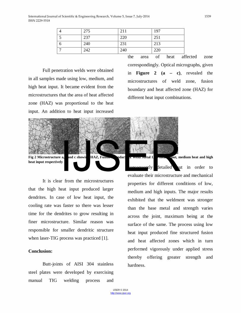
Full penetration welds were obtained
in all samples made using low, medium, and
high heat input. It became evident from the
microstructures that the area of heat affected
zone (HAZ) was proportional to the heat
input. An addition to heat input increased
the area of heat affected zone
correspondingly. Optical micrographs, given
in Figure 2 (a – c), revealed the
microstructures of weld zone, fusion
boundary and heat affected zone (HAZ) for
different heat input combinations.
Fig 2 Microstructure a,b and c showing HAZ, Fusion Boundary, & Weld Metal Low Heat Input, medium heat and high heat input respectively
It is clear from the microstructures
that the high heat input produced larger
dendrites. In case of low heat input, the
cooling rate was faster so there was lesser
time for the dendrites to grow resulting in
finer microstructure. Similar reason was
responsible for smaller dendritic structure
when laser-TIG process was practiced [1].
Conclusion:
Butt-joints of AISI 304 stainless
steel plates were developed by exercising
manual TIG welding process and
consequently detailed out in order to
evaluate their microstructure and mechanical
properties for different conditions of low,
medium and high inputs. The major results
exhibited that the weldment was stronger
than the base metal and strength varies
across the joint, maximum being at the
surface of the same. The process using low
heat input produced fine structured fusion
and heat affected zones which in turn
performed vigorously under applied stress
thereby offering greater strength and
hardness.
IJSER
International Journal of Scientific & Engineering Research, Volume 5, Issue 7, July-2014 1540 ISSN 2229-5518
IJSER © 2014 http://www.ijser.org
T.A.Tabish, Institute of Advanced Materials, Bahauddin Zakariya University, 60800, Multan.Pakistan T.Abbas, Institute of Advanced Materials, Bahauddin Zakariya University, 60800, Multan.Pakistan M.Farhan, Institute of Advanced Materials, Bahauddin Zakariya University, 60800, Multan.Pakistan S.Atiq, Institute of Advanced Materials, Bahauddin Zakariya University, 60800, Multan.Pakistan T.Z.Butt,Faculty of Engineering and Technology, University of the Punjab, 54590, Lahore, Pakistan
1 Corresponding author: email address: [email protected] (T.A.Tabish)
References:
[1] Jun Yan, Ming Gao, Xiaoyan Zeng,
Study on microstructure and mechanical
properties of 304 stainless steel joints by
TIG, laser and laser-TIG hybrid welding
Optics and Lasers in Engineering, 48 (2010)
512–517
[2] T. Sakthivel, M. Vasudevan, K. Laha, P.
Parameswaran, K.S. Chandravathi, M.D.
Mathew, A.K. Bhaduri, Comparison of
creep rupture behaviour of type 316L(N)
austenitic stainless steel joints welded by
TIG and activated TIG welding processes
Materials Science and Engineering A, 528
(2011) 6971– 6980
[3] P. Sathiya, S. Aravindan, A. Noorul Haq,
Effect of friction welding parameters on
mechanical and metallurgical properties of
ferritic stainless steel, The International
Journal of Advanced Manufacturing
Technology, 31, 11-12 (2007) 1076–1082
[4] Hidetoshi Fujii, Toyoyuki Sato,
Shanping Lua, Kiyoshi Nogi, Development
of an advanced A-TIG (AA-TIG) welding
method by control of Marangoni convection,
Materials Science and Engineering A, 495
(2008) 296–303
[5] Zhiguo Gao, Yixiong Wu, Jian Huang,
Analysis of weld pool dynamic during
stationary laser–MIG hybrid welding, The
International Journal of Advanced
Manufacturing Technology, 44, 9-10,(2009)
870-879
[6] Paskell, T., Lundin, C. & Castner, H.
Gtaw flux increases weld joint
penetration.Welding Journal, 76 (1997) 4,
57–62,
[7] M. Tanaka, T. Shimizu, T. Terasaki, M.
Ushio, F. Koshiishi, C.-L Yang, Effects of
activating flux on arc phenomena in gas
tungsten arc welding, Science and
Technology of Welding & Joining, 5 (2000)
6, 397-402
[8] Kuang-Hung Tseng, Chih-Yu Hsu,
Performance of activated TIG process in
IJSER
International Journal of Scientific & Engineering Research, Volume 5, Issue 7, July-2014 1541 ISSN 2229-5518
IJSER © 2014 http://www.ijser.org
austenitic stainless steel welds Journal of
Materials Processing Technology, 211
(2011) 503–512
[9] Halil İbrahim Kurt1, Ramazan Samur,
Study on Microstructure, Tensile Test and
Hardness 304 Stainless Steel Jointed by TIG
Welding, International Journal of Science
and Technology, 2 (2013) 163-168
[10] L.S. Kumar1, S.M.Verma, P.R.K.
Prasad, P.K. Kumar, T.S. Shanker,
Experimental Investigation for Welding
Aspects of AISI 304 & 316 by Taguchi
Technique for the Process of TIG & MIG
Welding, International Journal of
Engineering Trends and Technology, 2
(2011) 28-33 IJSER