Embed Size (px)
Citation preview
[Fattah et al., 3(7): July, 2016] ISSN 2349-4506 Impact Factor: 2.545
Global Journal of Engineering Science and Research Management
http: // www.gjesrm.com © Global Journal of Engineering Science and Research Management
[118]
EFFECT OF GEOCELL REINFORCEMENT IN THE MITIGATION OF TRAFFIC
LOADS TRANSMITTED TO THE FLEXIBLE BURIED PIPES Mohammed Y. Fattah*, Wallaa B. Mohammed Redha
* Professor, Building and Construction Engineering Department, University of Technology, Baghdad,
Iraq
Assistant lecturer, Civil Engineering Department, University of Karbala, Karbala, Iraq
DOI: 10.5281/zenodo.58281
KEYWORDS: Traffic load, geocell reinforcement, buried pipe, sandy soil, position.
ABSTRACT Buried pipeline systems are commonly used to transport water, sewage, natural oil/gas and other materials. They
are classified as lifelines since they carry essential materials for the support of human life. Dynamic vertical loads
like traffic loads present a severe hazard for these systems. Although there are some standards and instructions
for design (e.g. ASTM D 2321-08; BSI, 1980), installation and maintenance of buried pipes, nevertheless backfill
material optimization needs to be studied, particularly in the case of geocell-reinforced backfill material.
The present study presents the results of laboratory model tests conducted on small diameter PVC (Poly Vinyl
Chloride) pipe, buried in geocell reinforced sand beds. The aim of the study is to evaluate the suitability of the
geocell reinforcement in protecting the underground utilities and buried pipes from the dynamic traffic load. A
PVC pipe with external diameter 110 mm and thickness 1.4 mm was used in the experiments to simulate the
buried pipe. The vehicles dynamic load was simulated by applying the load on the top a steel plate placed on the
surface of the sandy soil with the help of a manufactured physical model.
A series of laboratory model tests has been performed to study the behavior of geocell-reinforced sand under
dynamic load.
It was found that The optimum burial depth of the geocell (u) beneath the footing and the appropriate width of the
reinforcing under dynamic loads were approximately 0.1 and 3.2 times the footing width (B), respectively, (i.e.
u/B = 0.1 and b/B = 3.2). In general, reinforcing the sandy soils with geocell leads to a beneficial reduction in
dynamic response (surface settlement, displacement amplitude, and transmitted dynamic pressure) for all soil
states in different percentages. This is accompanied by an increase in soil strength, as well as, reduces the hazards
of traffic load.
INTRODUCTION Buried pipes are classified as either rigid or flexible. A flexible pipe is defined as one that will deflect at least 5
percent of its diameter without structural distress while rigid pipe is generally considered a pipe that cannot deflect
2% of its diameter before failing. The procedure employed in the design of buried pipelines is basically the same
as in the design of any other structure. First, it is necessary to determine the loads to which the pipe will be
subjected in service, such as the overburden earth load plus any traffic and impact load. Also in case of pressure
pipes, the magnitude of the internal pressure must be determined.
The second step in the structural design of a buried pipe is the determination of its supporting strength, that is, its
ability to carry the load to which it will be subjected, with an appropriate margin of safety. The supporting strength
of the pipe primarily depends on three factors: the inherent strength of the pipe which depends upon modulus of
elasticity, diameter, thickness, and material; the distribution of the vertical load and the bottom reaction; and the
magnitude and distribution of the lateral earth pressure which may act against the sides of the structure (Bashir,
2000).
Ground improvement using the soil reinforcement technique has grown substantially in the last three decades.
The technique has grown from the use of metal grids to use of geosynthetic products such as geocells to reinforce

[Fattah et al., 3(7): July, 2016] ISSN 2349-4506 Impact Factor: 2.545
Global Journal of Engineering Science and Research Management
http: // www.gjesrm.com © Global Journal of Engineering Science and Research Management
[119]
the soil. Nowadays, the geocells are being widely used in geotechnical engineering to strengthen the soft soil.
General applications of geocell include pavements, foundations and embankments. By virtue of its 3-dimensional
box like structure, geocell provides additional confinement to the soil. Geocells offers faster, cheaper, sustainable,
and environmentally friendly solutions to many complex geotechnical problems.
In civil and road construction, underground utilities and buried pipes are widely used for different purposes, such
as transporting water, chemicals, and gases. Therefore, damage of these systems can result in heavy loss of
functionality with the consequential interference to the economic and social recovery in the areas where the
damage occurred and, also, at the end of thelifeline, possibly allowing illnesses and epidemics to develop.
Dash et al. (2007) studied the behavior of geocell-reinforced sand beds under strip loading, a series of laboratory
model tests have been performed to study the behavior of geocell-reinforced sand beds under strip loading. The
strain in geocell walls, pressure transmitted to the subgrade soil, and deformations in the subgrade were measured
during the tests. The pattern of strain variation in the geocell walls indicates that the geocell mattress behave as a
composite beam supported by the subgrade soil. The load dispersion in the geocell mattress is found to be
governed by factors such as geometry of the geocell layer and its placement position under the footing.
Goltabar and Shekarchi, (2010) studied the effects of a truck load on the buried pipeline which were done with
numerical and experimental methods. In numerical method, model is assumed half extreme and length of them
are considered extreme, mathematically. For performing of the numerical method, 3Diamentional models were
used in Plaxis-3Diamentional software.
For comparison and checking of results, experimental model was prepared and with using of electrical strain gages
and computer, the results of experimental model were recorded. Results showed that the experimental and finite
element models results are compatible.
Hegde et al. (2015) performed an experimental and numerical studies on protection of buried pipelines and
underground utilities using geocells the laboratory tests were conducted on small diameter PVC (Poly Vinyl
Chloride) pipes buried in unreinforced and geosynthetic reinforced sand subjected to static loading. The aim of
the study was to evaluate the appropriateness of the combination of geocell and geogrid reinforcement system in
protecting the underground utilities and buried pipelines. A pipe with external diameter of 75 mm and thickness
of 1.4 mm was placed below the footing at different depths ranging from 1B to 2B (B is the width of the footing).
Commercially available Neoweb geocells and biaxial geogrids were used as the reinforcements. Results indicated
that the use of a combination of geocell and the geogrid reinforcement system considerably reduces the
deformation of the pipe as compared to unreinforced bed.
Fattah et al. (2015) focused on the effect of the geogrid reinforcement in transfer of the dynamic load to the
underground structure. The underground structure was simulated as a PVC pipe inside the soil. In order to
investigate the response of soil, footing and underground tunnel to dynamic loading, a physical model was
manufactured. The manufactured physical model could be used to simulate the application of dynamic loading.
The response of the tunnel to dynamic loading includes measuring the pressure above the crown of the tunnel by
using pressure cell as well as measuring the amplitude of displacement by using a vibration meter. The response
of footing was elaborated by measuring the total settlement by using sensors in the dynamic load apparatus.
The main objectives of this research are evaluating the suitability of the geocell reinforcement in decreasing the
transfer dynamic loading to the underground utilities and buried pipes, investigating the displacement amplitude
that occurs above underground structures, especially buried pipes due to dynamic loads induced by moving
vehicles and investigating the influence of geocell reinforcement on the surface settlement that occurs due to
dynamic loading.
[Fattah et al., 3(7): July, 2016] ISSN 2349-4506 Impact Factor: 2.545
Global Journal of Engineering Science and Research Management
http: // www.gjesrm.com © Global Journal of Engineering Science and Research Management
[120]
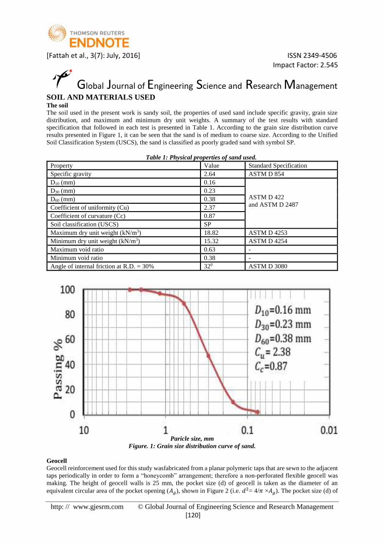
SOIL AND MATERIALS USED The soil
The soil used in the present work is sandy soil, the properties of used sand include specific gravity, grain size
distribution, and maximum and minimum dry unit weights. A summary of the test results with standard
specification that followed in each test is presented in Table 1. According to the grain size distribution curve
results presented in Figure 1, it can be seen that the sand is of medium to coarse size. According to the Unified
Soil Classification System (USCS), the sand is classified as poorly graded sand with symbol SP.
Table 1: Physical properties of sand used.
Property Value Standard Specification
Specific gravity 2.64 ASTM D 854
D10 (mm) 0.16
ASTM D 422
and ASTM D 2487
D30 (mm) 0.23
D60 (mm) 0.38
Coefficient of uniformity (Cu) 2.37
Coefficient of curvature (Cc) 0.87
Soil classification (USCS) SP
Maximum dry unit weight (kN/m3) 18.82 ASTM D 4253
Minimum dry unit weight (kN/m3) 15.32 ASTM D 4254
Maximum void ratio 0.63 -
Minimum void ratio 0.38 -
Angle of internal friction at R.D. = 30% 320 ASTM D 3080
Paricle size, mm
Figure. 1: Grain size distribution curve of sand.
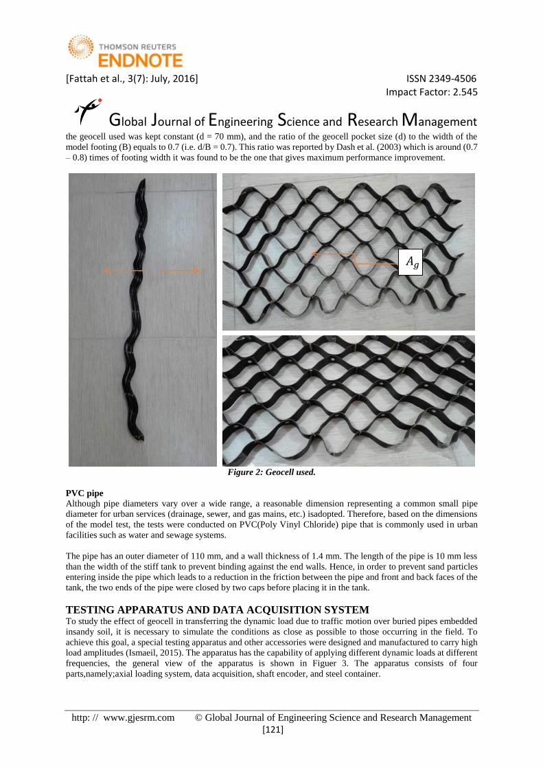
Geocell
Geocell reinforcement used for this study wasfabricated from a planar polymeric taps that are sewn to the adjacent
taps periodically in order to form a “honeycomb” arrangement; therefore a non-perforated flexible geocell was
making. The height of geocell walls is 25 mm, the pocket size (d) of geocell is taken as the diameter of an
equivalent circular area of the pocket opening (𝐴𝑔), shown in Figure 2 (i.e. 𝑑2= 4/𝜋 ×𝐴𝑔). The pocket size (d) of
[Fattah et al., 3(7): July, 2016] ISSN 2349-4506 Impact Factor: 2.545
Global Journal of Engineering Science and Research Management
http: // www.gjesrm.com © Global Journal of Engineering Science and Research Management
[121]
the geocell used was kept constant (d = 70 mm), and the ratio of the geocell pocket size (d) to the width of the
model footing (B) equals to 0.7 (i.e. d/B = 0.7). This ratio was reported by Dash et al. (2003) which is around (0.7
– 0.8) times of footing width it was found to be the one that gives maximum performance improvement.
Figure 2: Geocell used.
PVC pipe Although pipe diameters vary over a wide range, a reasonable dimension representing a common small pipe
diameter for urban services (drainage, sewer, and gas mains, etc.) isadopted. Therefore, based on the dimensions
of the model test, the tests were conducted on PVC(Poly Vinyl Chloride) pipe that is commonly used in urban
facilities such as water and sewage systems.
The pipe has an outer diameter of 110 mm, and a wall thickness of 1.4 mm. The length of the pipe is 10 mm less
than the width of the stiff tank to prevent binding against the end walls. Hence, in order to prevent sand particles
entering inside the pipe which leads to a reduction in the friction between the pipe and front and back faces of the
tank, the two ends of the pipe were closed by two caps before placing it in the tank.
TESTING APPARATUS AND DATA ACQUISITION SYSTEM To study the effect of geocell in transferring the dynamic load due to traffic motion over buried pipes embedded
insandy soil, it is necessary to simulate the conditions as close as possible to those occurring in the field. To
achieve this goal, a special testing apparatus and other accessories were designed and manufactured to carry high
load amplitudes (Ismaeil, 2015). The apparatus has the capability of applying different dynamic loads at different
frequencies, the general view of the apparatus is shown in Figuer 3. The apparatus consists of four
parts,namely;axial loading system, data acquisition, shaft encoder, and steel container.
𝐴𝑔

[Fattah et al., 3(7): July, 2016] ISSN 2349-4506 Impact Factor: 2.545
Global Journal of Engineering Science and Research Management
http: // www.gjesrm.com © Global Journal of Engineering Science and Research Management
[122]
Figure 3: General view of the apparatus.
The data acquisition that was used in this investigation isa Programmable Logic Controller (PLC) and can be
defined as a digital computer used for automation of electro-mechanical processes, which are considered as a high
technical process unit. This system analyzes the data digitally, according to the research requirement. PLC, unlike
general –purpose computers, can be designed for multiple inputs and outputs arrangements extend temperature
ranges and immunity to electrical noise, Figure 3 shows the data acquisition system.
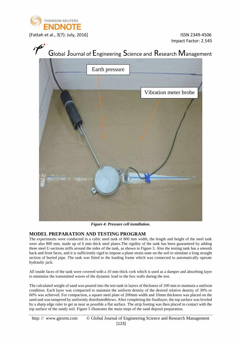
INSTRUMENTATION Earth pressure cell A heavy duty cell Model 3515 Geokon pressure cell was used, which is suitable for traffic applications. The
pressure cell was placed just above the pipe crown beneath the simulated road as shown in Figure 4. This earth
pressure cell has a diameter of 100 mm and a capacity of 0-250 kPa.
Vibration meter The vertical displacement amplitude of the pipe crown was measured at the surface of the pipe. Vibration meter
(VT-8204) of one channel was used in the test. This vibration meter has a working capacity of 0.001 to 2.217 mm,
it is capable of measuring the displacement, velocity, and acceleration of motion depending on the function set
prior to the test. In addition, all the collected data can be transferred to the computer easily through built-in
software.
[Fattah et al., 3(7): July, 2016] ISSN 2349-4506 Impact Factor: 2.545
Global Journal of Engineering Science and Research Management
http: // www.gjesrm.com © Global Journal of Engineering Science and Research Management
[123]
Figure 4: Pressure cell installation.
MODEL PREPARATION AND TESTING PROGRAM The experiments were conducted in a cubic steel tank of 800 mm width, the length and height of the steel tank
were also 800 mm, made up of 6 mm thick steel plates.The rigidity of the tank has been guaranteed by adding
three steel U-sections stiffs around the sides of the tank, as shown in Figure 3. Also the testing tank has a smooth
back and front faces, and it is sufficiently rigid to impose a plane strain state on the soil to simulate a long straight
section of buried pipe. The tank was fitted to the loading frame which was connected to automatically operate
hydraulic jack.
All inside faces of the tank were covered with a 10 mm thick cork which is used as a damper and absorbing layer
to minimize the transmitted waves of the dynamic load to the box walls during the test.
The calculated weight of sand was poured into the test tank in layers of thickness of 100 mm to maintain a uniform
condition. Each layer was compacted to maintain the uniform density of the desired relative density of 30% or
60% was achieved. For compaction, a square steel plate of 200mm width and 10mm thickness was placed on the
sand and was tampered by uniformly distributedblows. After completing the finallayer, the top surface was leveled
by a sharp edge ruler to get as near as possible a flat surface. The strip footing was then placed in contact with the
top surface of the sandy soil. Figure 5 illustrates the main steps of the sand deposit preparation.
Vibration meter brobe
Earth pressure
cell

[Fattah et al., 3(7): July, 2016] ISSN 2349-4506 Impact Factor: 2.545
Global Journal of Engineering Science and Research Management
http: // www.gjesrm.com © Global Journal of Engineering Science and Research Management
[124]
Figure 5: Preparation stages of the test model.
A series of laboratory model tests were conducted to study the behavior of geocell-reinforced sand under dynamic
load. Various parameters examined in this study include the load amplitude (0.5, and 1 ton), frequency of load
(0.5, 1, and 2 Hz), and relative density of sandy soil (30% for loose state, and 60% for medium state).
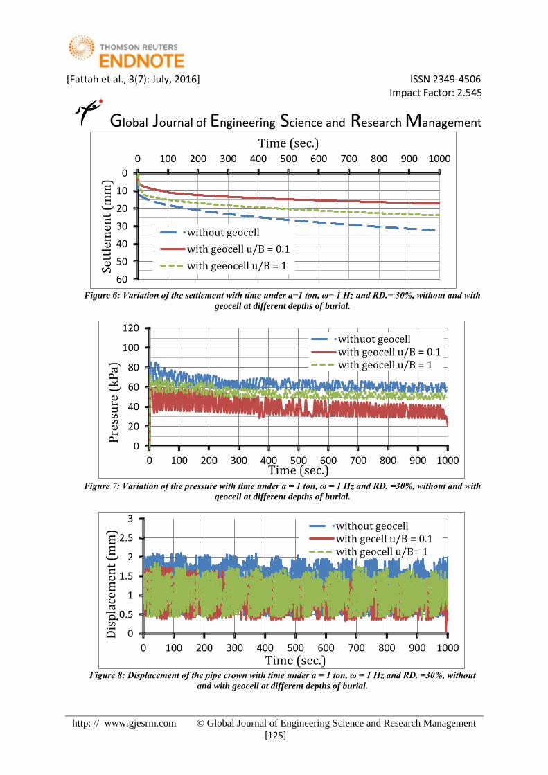
RESULTS AND DISCUSSION Effect of depth of placement of geocell (u) This model was tested under dynamic load amplitude equals to 1 ton and frequency of load was 1 Hz and the
geocell was placed at a depth equals to (1B) from the surface and the width of goecell reinforcement remains
constant (3.2B) as that for the all previous tests. The test results of this model are demonstrated in Figures 7 to 8.
It is clearly noted that the percent of improvement of geocell reinforcement decreased as compared with the same
test result, but with (u) equal to (0.1B). According to the test results, it can be said that the value chosen for the
depth of burial was appropriate. Similar findings for footing under monotonic loading have been obtained by
Sitharam and Sireesh (2005) and Yoon, et al., (2008).
The role of the slim layer of sand above the geocell reinforcement is to act as a cushion, preventing the direct
contact of the footing base with the cell walls, and distributing the footing pressure more uniformly over the
cellular geocell. In addition, Figure 9 shows the geocell reinforcement at the end of test.
Furthermore, geocell reinforcement of a soil results, in part, in the generation of apparent cohesion. An
experimental study performed by Rajagopal et al. (1999) showed the development of an apparent cohesion even
when using geocell in a non-cohesive soil. In addition the friction is increased to some extent (Zhang et al., 2008)
The geocell layer can reduce the spread and intensity of shear strain under the footing, also tending to reduce both
soil surface settlement and pipe deflection.
[Fattah et al., 3(7): July, 2016] ISSN 2349-4506 Impact Factor: 2.545
Global Journal of Engineering Science and Research Management
http: // www.gjesrm.com © Global Journal of Engineering Science and Research Management
[125]
Figure 6: Variation of the settlement with time under a=1 ton, ω= 1 Hz and RD.= 30%, without and with
geocell at different depths of burial.
Figure 7: Variation of the pressure with time under a = 1 ton, ω = 1 Hz and RD. =30%, without and with
geocell at different depths of burial.
Figure 8: Displacement of the pipe crown with time under a = 1 ton, ω = 1 Hz and RD. =30%, without
and with geocell at different depths of burial.
0
10
20
30
40
50
60
0 100 200 300 400 500 600 700 800 900 1000
Sett
lem
ent
(mm
)
Time (sec.)
without geocell
with geocell u/B = 0.1
with geeocell u/B = 1
0
20
40
60
80
100
120
0 100 200 300 400 500 600 700 800 900 1000
Pre
ssu
re (
kP
a)
Time (sec.)
withuot geocellwith geocell u/B = 0.1with geocell u/B = 1
0
0.5
1
1.5
2
2.5
3
0 100 200 300 400 500 600 700 800 900 1000
Dis
pla
cem
ent
(mm
)
Time (sec.)
without geocellwith gecell u/B = 0.1with geocell u/B= 1

[Fattah et al., 3(7): July, 2016] ISSN 2349-4506 Impact Factor: 2.545
Global Journal of Engineering Science and Research Management
http: // www.gjesrm.com © Global Journal of Engineering Science and Research Management
[126]
Figure 9: Geocell reinforcement within model test.
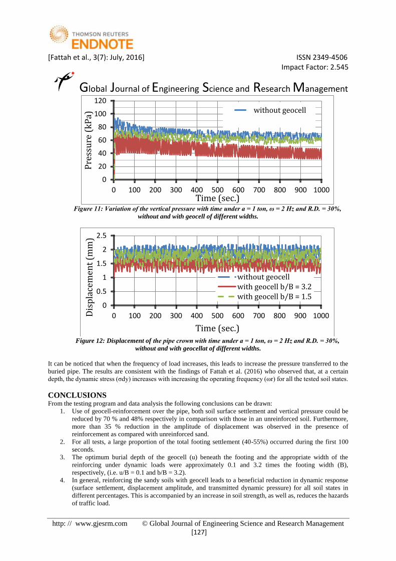
Effect of width of geocell (b) Dry loose sand model was tested under dynamic load amplitude equal to (1) ton, (2 Hz) frequency of the load, the
width of geocell was (1.5B) and the depth of burial of geocell was (0.1B).
Figures 10 to 12 illustrate the test results of the influence of geocell reinforcement width (b) on the surface
settlement, transmitted pressure, and the displacement amplitude on the pipe crown, respectively.
Obviously, it can be seen that, there is a noticeable reduction in the improvement percent when the width of
geocell reinforcement decreased from (3.2) times the footing width to (1.5B). This behavior can be attributed to
the geocell reinforcement which is acting as an interconnected cage, its vertical walls are serving as a series of
plate anchors that mobilizes substantial resistance against the footing settlement, as well as increasing the
performance improvement.
These results are compatible with the findings of Tafreshi and Dawson (2012) who concluded that, the
performance of reinforcement in decreasing the settlement of footing increases with an increase in the
reinforcement width until (b/B = 3.2), beyond which there is only a small further decrease in footing settlement,
so that can be neglected.
Figure 10: Variation of the settlement with time under a =1 ton, ω = 2 Hz and R.D. = 30%, without
and with geocell of different widths.
0
10
20
30
40
50
60
0 100 200 300 400 500 600 700 800 900 1000
Sett
lem
ent
(mm
)
Time (sec.)
without geocellwith geocell b/B = 3.2with geocell b/B = 1.5
[Fattah et al., 3(7): July, 2016] ISSN 2349-4506 Impact Factor: 2.545
Global Journal of Engineering Science and Research Management
http: // www.gjesrm.com © Global Journal of Engineering Science and Research Management
[127]
Figure 11: Variation of the vertical pressure with time under a = 1 ton, ω = 2 Hz and R.D. = 30%,
without and with geocell of different widths.
Figure 12: Displacement of the pipe crown with time under a = 1 ton, ω = 2 Hz and R.D. = 30%,
without and with geocellat of different widths.
It can be noticed that when the frequency of load increases, this leads to increase the pressure transferred to the
buried pipe. The results are consistent with the findings of Fattah et al. (2016) who observed that, at a certain
depth, the dynamic stress (σdy) increases with increasing the operating frequency (ωr) for all the tested soil states.
CONCLUSIONS From the testing program and data analysis the following conclusions can be drawn:
1. Use of geocell-reinforcement over the pipe, both soil surface settlement and vertical pressure could be
reduced by 70 % and 48% respectively in comparison with those in an unreinforced soil. Furthermore,
more than 35 % reduction in the amplitude of displacement was observed in the presence of
reinforcement as compared with unreinforced sand.
2. For all tests, a large proportion of the total footing settlement (40-55%) occurred during the first 100
seconds.
3. The optimum burial depth of the geocell (u) beneath the footing and the appropriate width of the
reinforcing under dynamic loads were approximately 0.1 and 3.2 times the footing width (B),
respectively, (i.e. u/B = 0.1 and b/B = 3.2).
4. In general, reinforcing the sandy soils with geocell leads to a beneficial reduction in dynamic response
(surface settlement, displacement amplitude, and transmitted dynamic pressure) for all soil states in
different percentages. This is accompanied by an increase in soil strength, as well as, reduces the hazards
of traffic load.
0
20
40
60
80
100
120
0 100 200 300 400 500 600 700 800 900 1000
Pre
ssu
re (
kP
a)
Time (sec.)
without geocell
0
0.5
1
1.5
2
2.5
0 100 200 300 400 500 600 700 800 900 1000Dis
pla
cem
ent
(mm
)
Time (sec.)
without geocellwith geocell b/B = 3.2with geocell b/B = 1.5
[Fattah et al., 3(7): July, 2016] ISSN 2349-4506 Impact Factor: 2.545
Global Journal of Engineering Science and Research Management
http: // www.gjesrm.com © Global Journal of Engineering Science and Research Management
[128]
REFERENCES 1. American Society of Testing and Materials (ASTM) (2006). "Standard test method for specific gravity
of soil solids by water pycnometer" ASTM D854, West Conshohocken, Pennsylvania, USA.
2. American Society of Testing and Materials (ASTM) (2006). "Standard Test Method for Particle Size-
Analysis of Soils" ASTM D422-02 (2002), West Conshohocken, Pennsylvania, USA.
3. American Society of Testing and Materials (ASTM) (2008). "Standard Practice for Underground
Installation of Thermoplastic Pipe for Sewers and Other Gravity-Flow Applications" ASTM D2321-08,
West Conshohocken, Pennsylvania, USA.
4. American Society of Testing and Materials (ASTM) (2006). "Standard Test Method for Classification of
Soils for Engineering Purposes (Unified Soil Classification System)" ASTM D2487-06, West
Conshohocken, Pennsylvania, USA.
5. American Society of Testing and Materials (ASTM) (2006). "Standard Test Method for Maximum Index
Density and Unit Weight of Soils Using a Vibratory Table" ASTM D4253-00 (2006), West
Conshohocken,
Pennsylvania, USA.
6. American Society of Testing and Materials (ASTM) (2006). "Standard Test Method for Minimum Index
Density and Unit Weight of Soils and Calculation of Relative Density" ASTM D4254-00 (2006), West
Conshohocken, Pennsylvania, USA.
7. American Society of Testing and Materials (ASTM) (2006). "Standard Test Method for Direct Shear
Test of Soils Under Consolidated Drained
Conditions" ASTM D3080, West Conshohocken, Pennsylvania, USA.
8. Bashir R. (2000). "Analysis and Design of Buried Pipelines" M.Sc. Thesis, King Fahd University of
Petroleum & Minerals, Dhahran, Saudi Arabia.
9. Dash, S.K., Krishnaswamy, N.R., Rajagopal, K., (2001) "Bearing capacity of strip footings supported on
geocell reinforced sand", Geotextiles and Geomembranes, No. 19, pp. 235-256.
10. Dash, S.K., Sireesh, S., Sitharam, T.G., (2003). "Model studies on circular footing supported on geocell
reinforced sand underlain by soft clay". Geotextile and Geomembranes, Vol. 21, No. 4, pp. 197-219.
11. Dash, S.K., Rajagopal, K., Krishnaswamy, N.R., (2007). "Behavior of geocell reinforced sand beds under
strip loading". Canadian Geotechnical Journal, Vol. (44), No, (7), pp. 905-916.
12. Fattah, M. Y., Zbar, B. S., Al-Kalali, H. H. M., (2015), "Experimental Study on the Effect of Embedment
Depth of Buried Flexible Pipe Subjected to Static Load", Global Journal of Engineering Science and
Research Management, Vol. 2, No. (12), December, pp. 113-122.
13. Fattah, M. Y., Al-Mosawi, M. J., Al-Ameri, A. F. I., (2016), " Vibration Response of Saturated Sand -
foundation System", Earthquakes and Structures, Vol. 11, No. 1, pp. 83-107, DOI:
http://dx.doi.org/10.12989/eas.2016.11.1.083, Techno-Press, Ltd, Korea.
14. Goltabar, A. M. and Shekarchi, M. (2010), "Investigation of Traffic Load on the Buried Pipeline by
Using of Real Scale Experimental and Plaxis-3D Software", Journal of Applied Science, Engineering
and Technology. Vol. 2, pp. 107-113.
15. Hegde, A. M. and Sitharam, T. G. (2015), " Three-dimensional Numerical Analysis of Geocell-reinforced
Soft Clay Beds by Considering the Actual Geometry of Geocell Pockets", Canadian Geotechnical
Journal, No. 52, pp. 1-12.
16. Ismaeil, M. S., (2015), "Influence of Geogrid Reinforcement of Sand in Transfer of Dynamic Loading
to Underground Structure", M.Sc. thesis, Building and Construction Engineering Department, University
of Technology, Baghdad, Iraq.
17. Moghaddas Tafreshi, S. N., Dawson, A.R. (2012), "A Comparison of Static and Cyclic Loading
Responses of Foundations on Geocell-Reinforced Sand", Geotextiles and Geomembranes, Vol. 32, pp.
55-68.
18. Yoon, Y. W., Heo, S. B., Kim, S. K., (2008), "Geotechnical Performance of Waste Tires for Soil
Reinforcement from Chamber Test", Geotextiles and Geomembrances, Vol.26 (1), pp. 100-107.
19. Zhang, M. X., Zhou, H., Javadi, A. A., Wang, Z. W., (2008), "Experimental and Theoretical Investigation
of Strength of Soil Reinforced with Multi-Layer Horizontal-Vertical Orthogonal Elements", Journal of
Geotextiles and Geomembranes, No. 1, Vol. 26, pp. 1-13.