Embed Size (px)
Citation preview
1
Effect of gasified biomass fuel on load characteristics of an
intermediate-temperature solid oxide fuel cell and gas turbine hybrid system
Xiaojing Lva, Chenghong Gub, Xing Liua,Yiwu Wenga,*
a Key Laboratory for Power Machinery and Engineering of Ministry of Education, School of Mechanical
Engineering, Shanghai Jiao Tong University. Shanghai 200240, China
b Department of Electronic and Electrical Engineering, University of Bath, Bath, BA2 7AY, UK
Abstract
This work uses the mathematical model of an intermediate-temperature solid oxide fuel
cell and gas turbine (IT-SOFC/GT) hybrid system to study the effects of gasified biomass fuels
on system load characteristics. The system performance is investigated by using four types of
fuels in each adjusting mode. The relation between the fuel type and load adjusting mode is
obtained for users and designers to select the appropriate fuel for reasonable operation modes.
Results show that the hybrid system of 182.4kW has a high electric efficiency of 60.78% by
using wood chip gas (WCG). If cotton wood gas (CWG) and corn stalk gas (CSG) are used,
both boundary values of steam to carbon ratio (S/Cbv ) and system power are higher, but system
efficiencies decrease to 57.36% and 57.87% respectively. In the designed three load adjusting
modes, the system can reach maximum efficiency over 59% with four types of biomass gases.
If high efficiency and a wide range of load adjustment are required, users can select Case B to
use fuels like WCG and GSG. When higher efficiency and low load is expected, Case A is more
desirable. With fuels like CWG and CSG, the system has good safety performance in Case C.
*Corresponding author. Tel.: +86 21 3420 6342; fax: +86 21 3420 6342. E-mail address: [email protected].

2
Keywords: intermediate temperature solid oxide fuel cell; gas turbine; hybrid system; gasified
biomass gas; load characteristic; adjusting mode
1. Introduction
Solid oxide fuel cell and gas turbine (SOFC/GT) hybrid systems are thought to be the
most attractive energy conversion systems in future energy markets because of high efficiency,
low pollution, and fuel flexibility (such as natural gas, biomass gas) [1,2]. Biomass is rich and
important renewable energy and it has the characteristics of low net CO2 emission rate and SO2
emission rate. For this reason, biomass fuelled SOFC/GT hybrid systems are regarded as one of
the most promising power generation equipment [3,4].
In recent years, some theoretical and experimental research has been carried out in the
integrated systems based on biomass gasification and SOFC/GT systems [5-9]. These works
mainly focus on system modeling [5,6], integration and optimization design [7,8], and selection
and impact analysis of component operation parameters [9], providing the basis for utilizing
biomass gas in hybrid systems. Unlike fossil fuels, the components and quality of biomass gas
fuels are mainly affected by gasification process, process control parameters and raw materials
[10]. In biomass gasification, fuel compositions depend on the gasification agent. For example,
the concentrations of H2, CH4, CO, and N2 vary greatly when oxygen, air, or steam is used as
gasification agent [10,11].
However, the variation of fuel type (or composition) has a great impact on system
performance. The main reasons are as follows: 1) fuel cell electrochemical reaction is mainly
affected by temperature and fuel composition, and the composition variation will cause a large

3
fluctuation in fuel cell performance [10]; 2) Reforming reactions in reformers are reversible
thermodynamic equilibrium [12], which will occur automatically due to the changes in fuel
compositions; 3) The combined effect of the previous two factors can cause changes in the
thermodynamic performance of other components, and the design and layout of hybrid systems.
Magistri.et.al [13] showed that when the designed fuel CH4 was completely replaced by
synthetic gas and biomass gas, system efficiency decreased from 61.7% to 53.5% and 49.2%
respectively, and the selection of parameters for gas turbines and injector should also be
changed. Santin.et.al [14,15] investigated the SOFC/GT hybrid system with two liquid fuels
(methanol and kerosene) and developed four layouts by considering different fuel processing
strategies. They also conducted thermodynamic and investment analysis for the hybrid system.
Van herle.et.al [16] studied a process flow model of an SOFC system supplied with sewage
biogas. For partial oxidation of biogas or pure hydrogen feeding, electric efficiency dropped
under 43%. Zabihian.et.al [10] compared the output power, specific work, and efficiency of the
SOFC/GT hybrid system fueled with methane and various types of biomasses. Zabihian.et.al
[17,18] further investigated the effect of fuel composition on the hybrid system performance
from the perspective of inlet fuel energy content. Sucipta.et.al [19] found that the change of
H2O and H2 concentration in fuel from 0% to 50% slightly reduced the efficiency of hybrid
systems. An increase of CO concentration produced similar effects as that of CO2 and resulted
in a decreasing efficiency of both SOFC module and hybrid system significantly. Sucipta.et.al
[20] analyzed the electric performance of a biomass SOFC/GT hybrid system by comparing
typical air, oxygen, and steam-blown biomass gasification processes. Results showed that the
4
electric efficiencies of the three biomass fuel cases were lower than that of pure methane case.
Rokni.et.al [21] showed that the electric efficiency of a hybrid SOFC-Stirling plant was 60%.
With a slight decrease in fuel utilization factor, the power of Stirling engine was found to
increase. By lowering SOFC working temperature, the plant efficiency decreased for all fuels
except ammonia. Similar research could be found in [22-25].
All previous work has identified the change of fuel type and composition to be important
factors for a hybrid system at designed condition. However, the hybrid system is a
strongly-coupled thermoelectric system. With different types of inlet fuels, there are some
important issues will appear when the system operates under variable conditions due to the
constraints of component matching and characteristic parameters. For example, the issues could
be the influence of changes in fuel type on variable load operation and safety issues of a hybrid
system, and the coupling relationship between different types of fuels and various operations.
But, research in this field is very limited. Weng [26] studied the performance of a hybrid
system using CH4,H2 and ethanol as fuel. It was found that when the hybrid system operated
with H2, the net power output at the design point decreased to 70% of the CH4, while the design
net efficiency dropped to 55%. Similar to H2, the net output power of the ethanol-fueled system
fell below 88%.
Based on the previous research, this work studies the operating characteristics of the main
components (such as fuel cell, gas turbine, and reformer) of a hybrid system and its variable
load characteristics under design and off-design conditions, when the system is fueled with
different types of gasified gases. Then, the matching relationships between load adjusting mode

5
and fuel type are obtained by analysis and comparison. The results are very beneficial for
designers and users to select the most appropriate fuels for reasonable operation of a hybrid
system.
2. IT-SOFC/GT calculating method and parameter selection
2.1 IT-SOFC/GT hybrid system structure
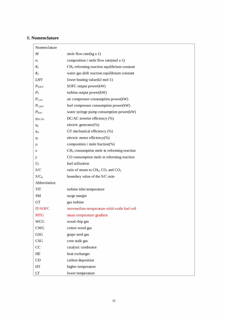
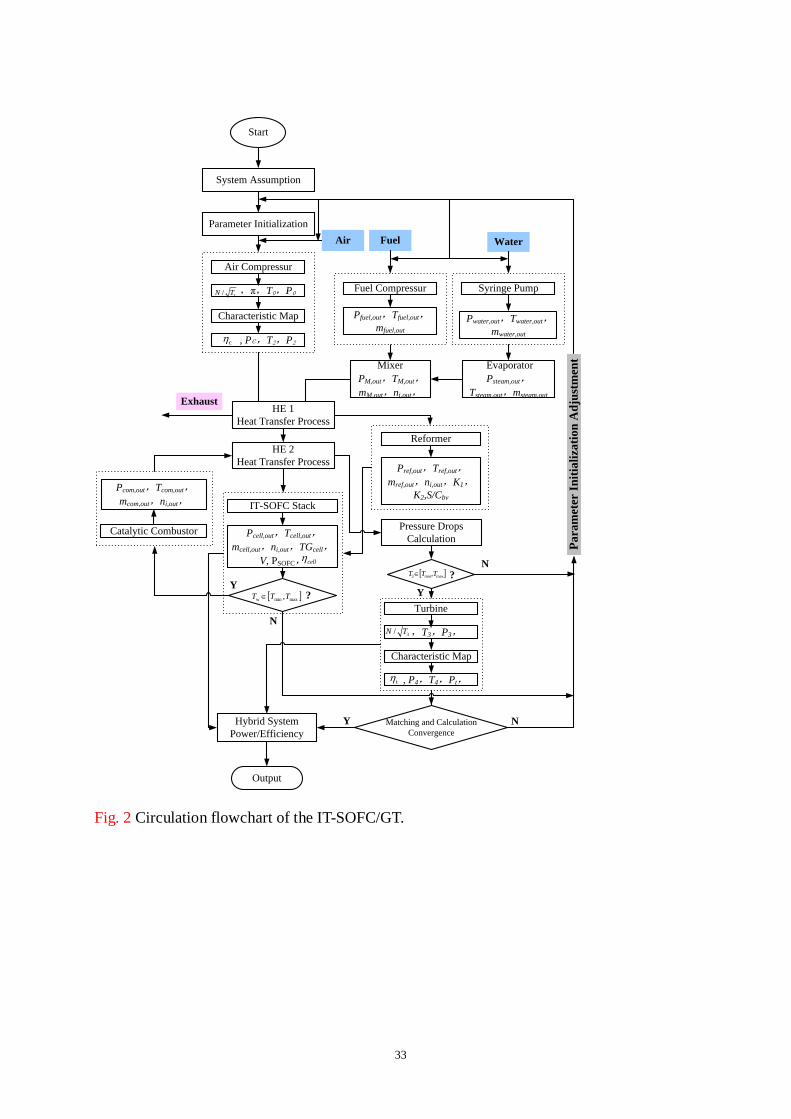
A schematic of the IT-SOFC/GT hybrid system is shown in Fig. 1, which mainly includes
IT-SOFC, single-shaft GT, external reformer, catalytic combustor (CC), fuel compressor, water
syringe pump, generator, and other components. To avoid carbon deposition, water is added for
maintaining the ratio of steam to carbon [16,27] by adjusting valve 1. To prevent seal and
vibration caused by the pressure difference between anode and cathode in the fuel cell [28],
biomass gas needs to be compressed by a fuel compressor before entering the fuel cell for
electrochemical reaction, which is adjusted by valve 2. The airflow is controlled by GT
adjustment system, and the rotational speed of GT is controlled by generator equipment. Air
pressurized by the compressor is heated by heat exchangers (HE) 1 and 2, which then enters the
SOFC cathode to provide O2 for electrochemical reaction. Water is first heated in the
evaporator to be converted into steam and then mixed with biomass gas in the mixer. The
mixed gas enters the reformer after being heated by HE 1. Reformed gas enters the anode of the
fuel cell to provide H2. The unreacted fuel from the SOFC anode will be completely combusted
in the CC. High-temperature gas enters the turbine to generate power after heating air. The
exhaust gas of the turbine preheats fuel and air, and then heats the evaporator before being
released into the atmosphere.
6
2.2 IT-SOFC/GT hybrid system modeling
The mathematical model of the IT-SOFC/GT was described in detail in the previous
literature [29,30]. All important equations of this model are shown in appendix A. The
modeling approach, mathematical formula, specific geometric parameters, physical parameters,
and operating conditions can be found in the literature [29,30].
In this paper, the anode-supported IT-SOFC (873–1073 K) developed by Aguiar [31] is
used to fit into the hybrid system. The 2D fuel cell model includes an electrochemical model
and a thermodynamic model based on mass and energy balance equations from Eqs (1)~(19), as
shown in Table A. The electrochemical model describes the function relation between fuel cell
voltage, various polarization losses, and current density. It considers not only the influence of
ohm, activation and concentration polarization losses on the Nernst potential, but also the
changes in gas composition caused by the electrochemical reaction and changes in specific heat
value caused by temperature variations. The fuel cell stack is assumed to have 912 planar fuel
cells, providing 144 kW power. Its working temperature, average current density, and fuel
utilization are chosen to be 1,073 K, 5,000 A/m2, and 75%, at the design condition respectively.
The gas turbine model is mainly composed of a centrifugal compressor and radial turbine.
It is represented by the characteristic maps of compressor and turbine shown in Figs. 2 and 3 in
[26, 30-31]. According to similarity theory, the characteristic curves of compressor and turbine
can be described by a set of functions with reduced parameters from Eqs (20)~(25, as shown in
Table A). For the compressor, surge boundary line is important. Therefore, the distance between
surge boundary and working point is measured by surge margin (SM). When SM is smaller, the
7
compressor is easier to surge and the formulas are presented in [30].
The reforming model is established according to Gibbs free energy thermodynamic
equilibrium reaction, mainly including strong endothermic steam reforming reaction (1) and
weak exothermic water gas shift reaction (2). Six type flows of CH4, H2, CO, CO2, H2O, and N2
in the reforming model can be calculated by the equilibrium Eqs. (3) and (4). H2 flow before
entering SOFC can be calculated by Eq. (5).
In reforming process, the S/C ratio (the ratio of steam to CH4, CO, and CO2) is an
important parameter to avoid carbon deposition [32]. The boundary value of the S/C ratio
(S/Cbv) is dependent on the reaction temperature [16], where the detailed formula is also
presented.
4 2 2CH +H O CO+3H
(1)
2 2 2CO+H O CO +H (2)
2 4 2
3 3 2
1 2 4 2[ ][ ] /[ ][ ] ( )( 3 ) /( )( )( 2 )CO H CH H O tK CO H CH H O n x y n x y n x n x y n x (3)
2 2 22 2 2 2[ ][ ] /([ ][ ]) ( )( 3 ) /[( )( )]CO H CO H OK CO H CO H O n y n x y n x y n x y (4)
2 2 4H ,tot H ,in CO,eq CH ,eq3n n n n (5)
The hybrid system also includes other components, such as CC, HE, mixer, and syringe
pump. The establishment of the models and parameters selection can be found in [26,33]. This
work assumes that unreacted fuel is completely combusted in the CC.
The hybrid system electric efficiency is:
4 4 2 2
DC/AC ,air ,fuel ,
0 0 0 0 0 0
( ) ( / ) ( / )
( )
SOFC T C g m C e P water e
HS
CH CH H H CO CO fuel
P P P P P
y LHV y LHV y LHV M
(6)

8
2.3 IT-SOFC/GT hybrid system calculation
Considering the thermal coupling between components and their safety constraints, a
reasonable and scientific calculation flowchart is important for analyzing the operating
performance of components and the variable load characteristics of the hybrid system. The
calculation flowchart of IT-SOFC/GT is shown in Fig. 2.
The proposed system mainly uses the following three functional models to calculate and
distinguish system circulation features: 1) thermodynamic calculation and component
parameter matching, 2) the self-estimation of main components, 3) iteration cycle and matching
of the whole system. The hybrid system is simulated in MATLAB/SIMULINK. The reforming
equilibrium reactions are solved using MATLAB programming, and the component estimation
modules are realized by user-defined functions.
The hybrid system is very complicated and its performance depends on many influencing
factors. Apart from H2, CO also participates in the electrochemical reaction, but its impact on
the hybrid system is far less than those of other factors. Additionally, a large number of system
integration and parameter variables make the thermodynamic calculation complex and difficult.
Hence, for simplicity purposes, some assumptions are made [2, 10, 28]: 1) In the SOFC, only
H2 participates in the electrochemical reaction, and the electrochemical reaction of CO is not
considered; 2) The hybrid system has zero leakage; 3) The output temperatures of the fuel cell
and reformer are their reaction temperatures; 4) Heat and pressure losses of components are
constants in operation conditions; 5) The operating voltage of each cell in stack is constant.
2.4 Determination for fuel and load adjusting mode
9
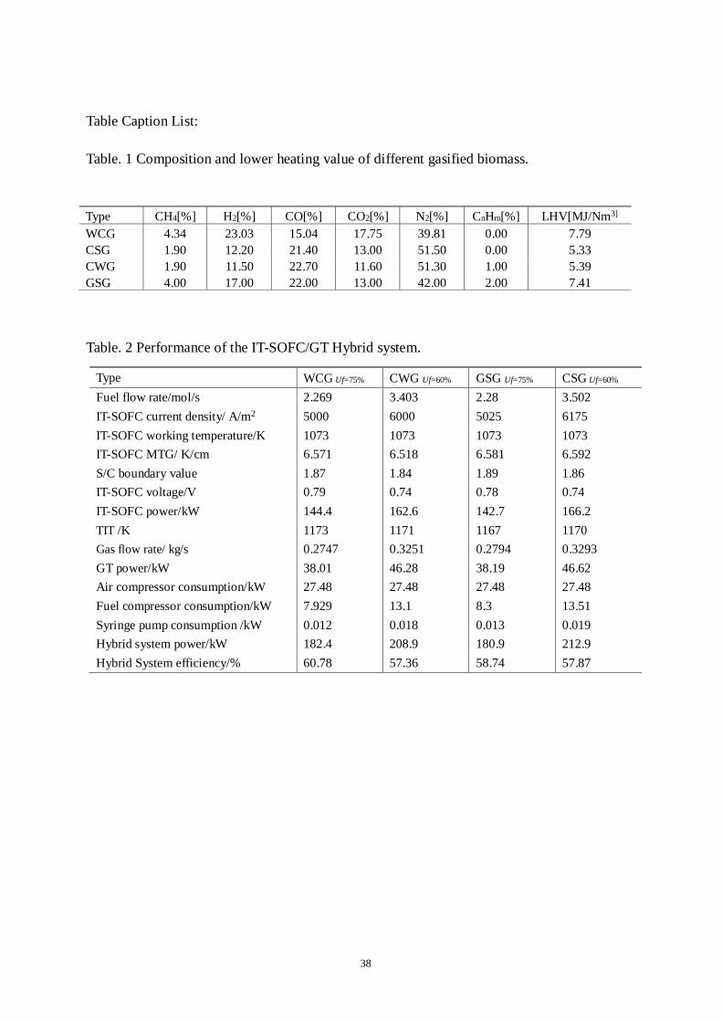
In this work, gasified wood chip gas (WCG) is used for the original system design, and
other three types of gasified biomass - cotton wood gas (CWG), grape seed gas (GSG) and corn
stalk gas (CSG) are selected for comparison and analysis. The composition and lower heating
value of gasification gases are shown in Table.1. The fuel composition is the experimental
results from a two-stage gasification developed by the Institute of Thermal Engineering,
Shanghai Jiao Tong University [34]. In air blown gasification process, pyrolysis zone and
gasification zone are independent, making the system simple and flexible and desirable
completion of pyrolysis, partial oxidation, and tar elimination. More information about the
gasification can be found in [34]. Gasified gas usually contains some impurities, but the impure
tar, particles, and H2S in the gasified biomass gas in this study are assumed to be removed well
in the purifying process. Thus, the effect of poison on the components or the system can be
neglected.
For variable load operation of a multi-hundred kW-class SOFC/GT hybrid system, two
types of load adjusting modes were proposed in previous studies: the fuel only adjusting mode
and rotational speed adjusting mode [35-36]. In variable load operations, the fuel cell working
temperature should be maintained close to its design value in order to reduce the decreasing
extent of system efficiency. Hence, in this study, the following three types of load adjusting
modes (Case A, Case B, and Case C) are adopted, and their fuel utilization factors for different
inlet fuels are assumed to be constant. The three models are defined as follows, and the
operating trajectories of the gas turbine are shown in Fig. 3.
Case A:Adjusting fuel proportionally and then adjusting the air to keep fuel cell working
10
temperature constant.
Case B:Adjusting the fuel but keeping the air constant.
Case C:Adjusting the fuel and air simultaneously to keep the fuel-air ratio constant.3.
Performance analysis of IT-SOFC/GT at design condition
It is important to note that, for different types of inlet fuels, fuel flow needs to be
recalculated before entering the hybrid system in order to maintain the SOFC working
temperature constant. When using WCG and GSG, the system operation performance can be
fulfilled by purely changing fuel flow with constant Uf , 75%. However, it does not work for
CWG and CSG, because that the heating values of these two fuels are lower. More seriously,
increasing the fuel flow to meet fuel cell operating requirement will lead the compressor
operating point to deviate into high pressure and low air flow zone, causing compressor surge
and unstable operation. Hence, decreasing the Uf from 75% to 60% is used to satisfy the safe
operation for the system when using CWG and CSG.
The operation performance at designed condition is obtained by using above established
IT-SOFC/GT mathematic models, as shown in Table 2. It can be observed that when using the
designed fuel WCG, the fuel flow rate is 2.269 mol/s, and all characteristic parameters of main
components meet the requirements in Table 3 in [29]. Furthermore, the fuel cell operating
parameters coincide with the results from reference [31]. For the small power system designed
in this work, the electrical efficiency is 60.78%. It is noted that the catalytic combustor
temperature is not more than 1200K and changes homogeneously, causing NOx emission to be
very low (nearly zero) [33] and CO to be converted into CO2 completely. Above results show
11
that the hybrid system has good emission and operation performance.
Notably that, for using non-design fuel, both the fuel flow rate and the current density are
higher than those of the design fuel. More importantly, when using CWG and CSG, S/Cbv and
the fuel cell voltage drop, the output power of fuel cell and GT are higher, leading the system
power to increase but the efficiencies to decrease to 57.36% and 57.87% respectively. In
addition, compressor consumption power increases significantly and is approximately 2 times
of that of the design fuel WCG, which needs the turbine to generate more power to meet the
system demand. However, for using GSG, S/Cbv increases and the fuel cell voltage decreases,
both the power and efficiency of the hybrid system are lower than those of design fuel. The
main reason is that the drop in the fuel cell power is higher than the rise in GT power.
It is also observed that all turbine inlet temperatures (TITs) are less than 1173K when
using non-design fuels and the GT output powers are higher than that of designed value. This is
due to the impact that the increasing fuel flow on the GT output power is greater than that of
decreasing TIT.
4. Analysis of the variable load characteristics of the hybrid system.
4.1 Variable load characteristics of the hybrid system in Case A
In this mode, the fuel flow increases from 0.4 times of the design value to 1.05 times
proportionally, and the air flow is controlled by adjusting the rotational speed of the gas turbine.
For variable rotational speed, in order to make each operating point have a maximum value of
surge margin, the operating trajectory of the gas turbine is obtained (depicted in light blue
heavy line ) in Fig.3. The purple heavy line stands for the operating trajectory for the gas
12
turbine using CWG and CSG as fuel.
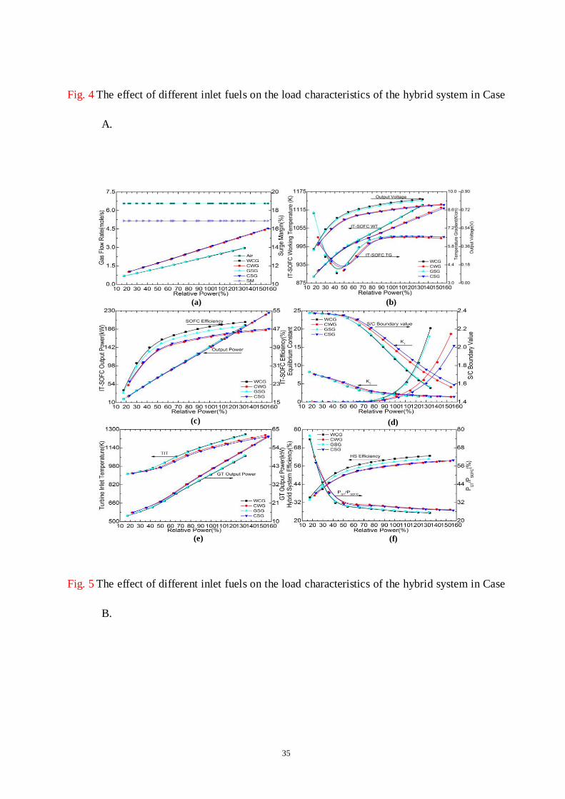
Fig. 4 (a) shows that for different inlet biomass types, both fuel flow and air flow increase
with increasing system load. Note that for using WCG and GSG, the fuel flow rates are nearly
equal, but are less than those of CWG and CSG. On the other hand, their corresponding air
flows are greater than those of CWG and CSG. Meanwhile, for using WCG and GSG, when the
gas turbine is operated at the same rotational speed, the compressor pressure is also less than
that of CWG and CSG, causing the compressor operating point to drift away from surge
boundary line and the surge margin to increase. As shown in Fig. 4 (a), for using WCG and
GSG, the SM is higher than that of other two types of fuels when the system load increases
from 46% to 80%. With increasing system load, the SM for four types of fuels has a downward
trend. It can also be found that the system load changes from 40% to 103% of the rated power
when using WCG and GSG, but for other two fuels, the system load ranges are 46.6%
~118.90% and 47.97%~121.12%, respectively.
Fig. 4 (b) shows that with increasing system load, the fuel cell working temperature is
constant and its mean temperature gradient increases, but the voltage drops. The mean
temperature gradients are higher than those of other two fuels when using WCG and GSG.
More importantly, when the system uses WCG, the fuel cell voltage is the highest, followed by
that of using GSG.
With increasing system load, the fuel cell output power increases but its efficiency
declines, as shown in Fig.4(c). For WCG, though the fuel cell efficiency is higher than that of
other fuels, it decreases from 53.73% to 47.69%. CSG fuel can make the fuel cell have a wider

13
and higher load adjusting range increasing from 75.85 kW to 172.32 kW, but cause its
efficiency to decrease from 52.24% to 44.62%. This is because, in order to keep fuel cell
temperature constant, the too low heating value of CSG makes the current density and fuel flow
rate both increase and the voltage decrease. This combined effect causes the increasing extent
of fuel cell power to be less than that of the heat value of the fuel entering the system, and the
ultimate consequence is the decreasing cell efficiency.
In reforming process, the increasing reaction equilibrium constant Ki means that the
forward reaction is performed, vice versa. Fig. 4(d) shows that with increasing system load, K1
decreases, K2 increases, and S/Cbv also increases. When using WCG, K1 is higher than that of
GSG, and is lower than those of other two fuels. However, S/Cbv is less than that of GSG and is
higher than those of other two fuels. This is mainly because the too low heating values of CWG
and CSG make the fuel flow increase greatly. The remaining fuel after electrochemistry
reaction will be combusted completely in the CC, triggering the reformer inner temperature to
increase, and finally K1 to increase and both K2 and S/Cbv to decrease. Thus, it can be seen that
high fuel flow, caused by low heating values of fuels, is beneficial for improving the reforming
characteristics and safety of the reformer by reducing Uf.
In Fig. 4 (e), with increasing system load, TIT changes a little due to the limitation from
constant SOFC working temperature. For using CWG as fuel, TIT is higher than that of other
three fuels- CSG, WCG, and GSG. This influence trend is similar to that of the reformer. It can
also be found that when using WCG and GSG, the gas turbine output power reaches the
maximum value at the designed point and then declines. Using other two fuels, the gas turbine
14
output power is higher those of WCG and GSG, but no maximum value exists. This further
proves that gas fuels of CWG and CSG with low heating value can improve the workability of
the gas turbine by reducing Uf. However, more attentions should be paid to the effect of higher
gas flows on the turbine flow characteristics in this case.
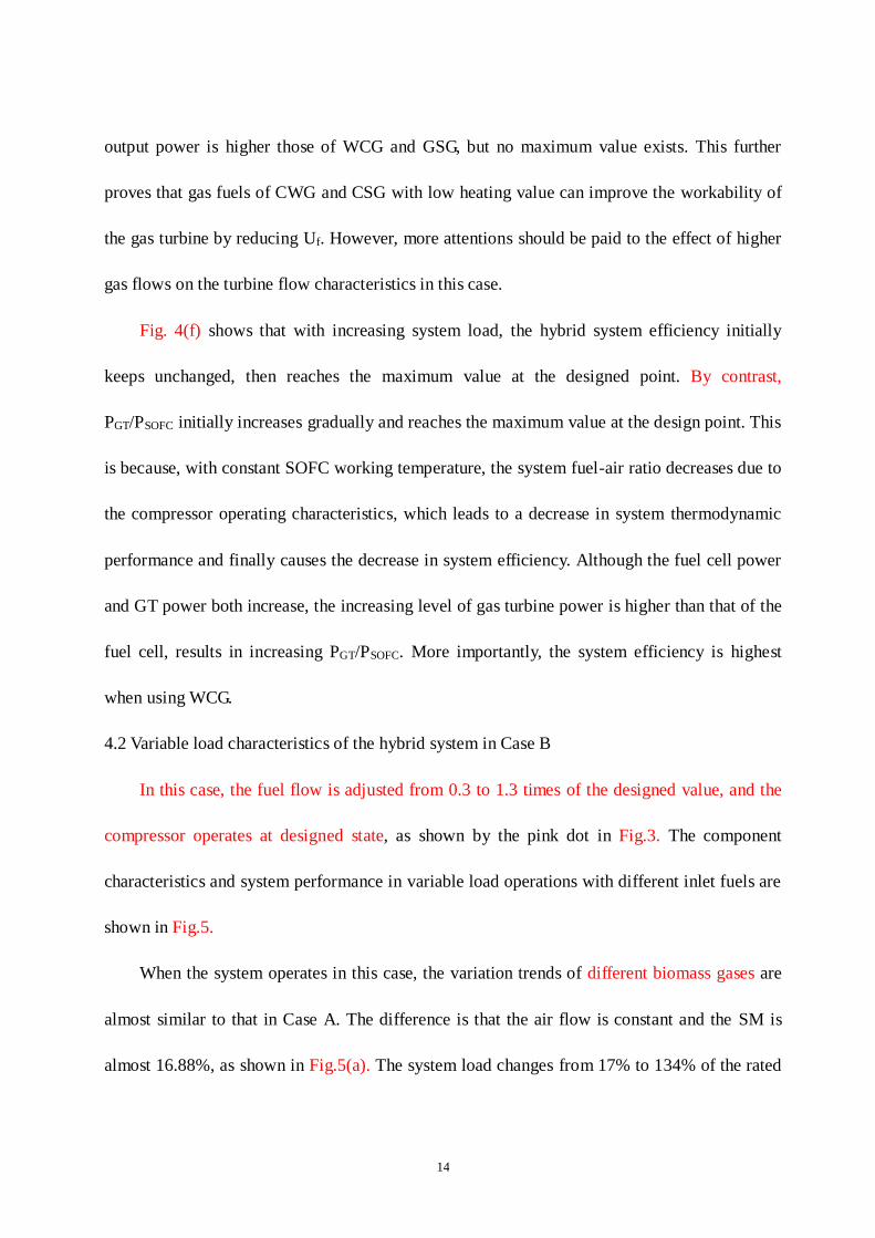
Fig. 4(f) shows that with increasing system load, the hybrid system efficiency initially
keeps unchanged, then reaches the maximum value at the designed point. By contrast,
PGT/PSOFC initially increases gradually and reaches the maximum value at the design point. This
is because, with constant SOFC working temperature, the system fuel-air ratio decreases due to
the compressor operating characteristics, which leads to a decrease in system thermodynamic
performance and finally causes the decrease in system efficiency. Although the fuel cell power
and GT power both increase, the increasing level of gas turbine power is higher than that of the
fuel cell, results in increasing PGT/PSOFC. More importantly, the system efficiency is highest
when using WCG.
4.2 Variable load characteristics of the hybrid system in Case B
In this case, the fuel flow is adjusted from 0.3 to 1.3 times of the designed value, and the
compressor operates at designed state, as shown by the pink dot in Fig.3. The component
characteristics and system performance in variable load operations with different inlet fuels are
shown in Fig.5.
When the system operates in this case, the variation trends of different biomass gases are
almost similar to that in Case A. The difference is that the air flow is constant and the SM is
almost 16.88%, as shown in Fig.5(a). The system load changes from 17% to 134% of the rated
15
power when using WCG and GSG. However, for other two fuels, the system load changes from
21.96% to 153.94% and from 23.23% to 156.89%, respectively.
Fig. 5(b) shows that with increasing system load, both fuel cell working temperature and
voltage increase while the cell mean temperature gradient has a minimum value. In the low
load condition, the variation trend of fuel cell working temperature appears to overlap with
each other, but with load increasing to 53%, the fuel cell working temperatures with using
WCG and GSG are higher than those of other two fuels. In the whole load variation process,
for using WCG and GSG, the voltage is higher than those of other two fuels. Meanwhile, in the
low load condition, the mean temperature gradient is higher for the first two fuels, but when the
load reaches rated state, the mean temperature gradients for all four fuel types are mostly
identical to 6.58K/cm.
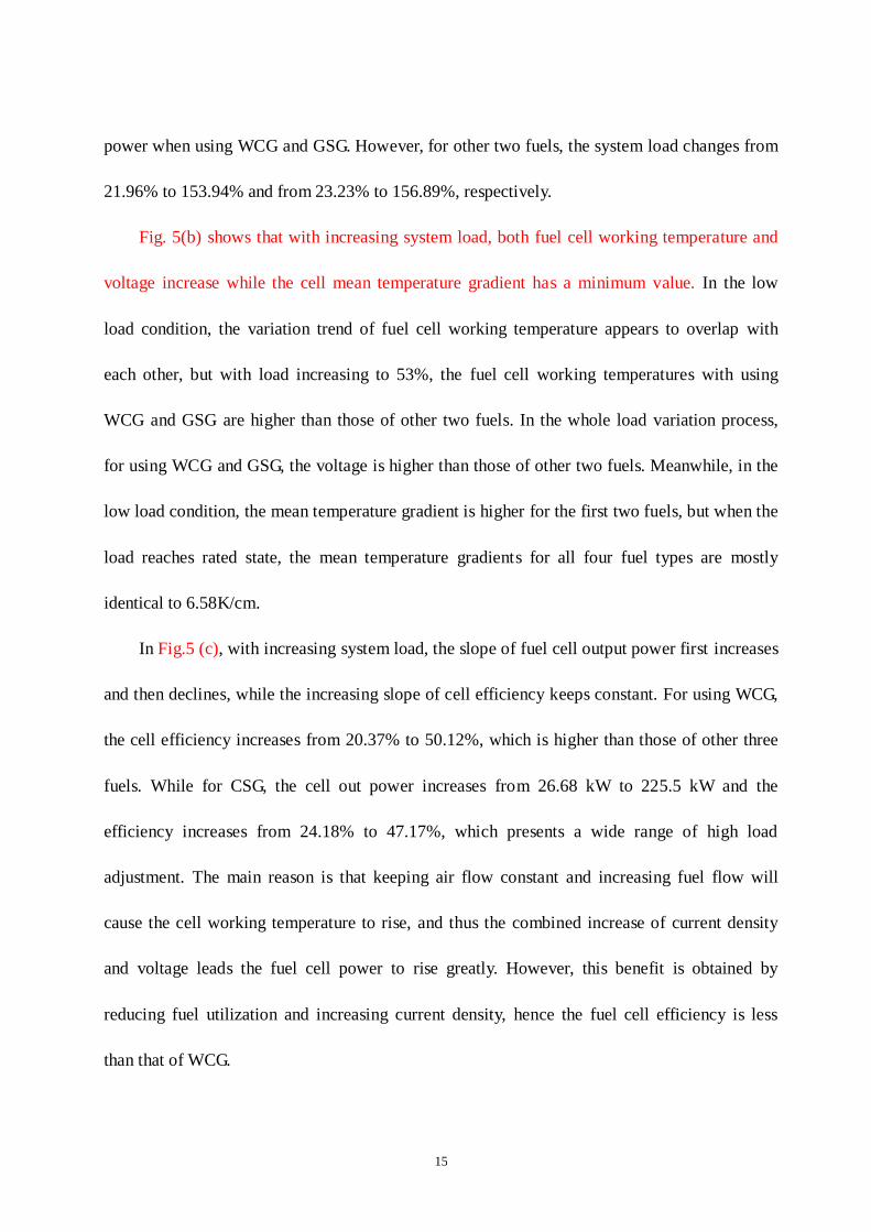
In Fig.5 (c), with increasing system load, the slope of fuel cell output power first increases
and then declines, while the increasing slope of cell efficiency keeps constant. For using WCG,
the cell efficiency increases from 20.37% to 50.12%, which is higher than those of other three
fuels. While for CSG, the cell out power increases from 26.68 kW to 225.5 kW and the
efficiency increases from 24.18% to 47.17%, which presents a wide range of high load
adjustment. The main reason is that keeping air flow constant and increasing fuel flow will
cause the cell working temperature to rise, and thus the combined increase of current density
and voltage leads the fuel cell power to rise greatly. However, this benefit is obtained by
reducing fuel utilization and increasing current density, hence the fuel cell efficiency is less
than that of WCG.
16
With increasing system load, K1 rises, but K2 and S/Cbv both decrease, as shown in
Fig.5(d). This is mainly because increasing fuel flow rises the reformer inner temperature,
which can promote the CH4 reforming in a forward direction due to its endothermic
characteristic. Thus, this can finally cause K1 to rise. While K2 declines, because of the
exothermic characteristic of water, gas shift reaction and increasing temperature promotes
reverse reaction. Rising temperature can effectively prevent carbon deposition at least in theory,
which leads to the decrease of S/Cbv. Most notably that when using WCG, K1 is the highest and
S/Cbv is the smallest. It is thus clear that the biomass gas CWG and CSG with low heating
value after reducing Uf have little impact on enhancing the reforming characteristics of the
reformer.
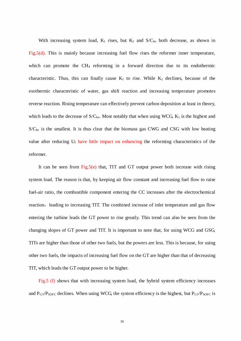
It can be seen from Fig.5(e) that, TIT and GT output power both increase with rising
system load. The reason is that, by keeping air flow constant and increasing fuel flow to raise
fuel-air ratio, the combustible component entering the CC increases after the electrochemical
reaction,leading to increasing TIT. The combined increase of inlet temperature and gas flow
entering the turbine leads the GT power to rise greatly. This trend can also be seen from the
changing slopes of GT power and TIT. It is important to note that, for using WCG and GSG,
TITs are higher than those of other two fuels, but the powers are less. This is because, for using
other two fuels, the impacts of increasing fuel flow on the GT are higher than that of decreasing
TIT, which leads the GT output power to be higher.
Fig.5 (f) shows that with increasing system load, the hybrid system efficiency increases
and PGT/PSOFC declines. When using WCG, the system efficiency is the highest, but PGT/PSOFC is

17
the smallest. The system efficiency changes greatly when the system load is lower than 55%,
and it is relatively flat when load is higher than 55% because the fuel cell is a major power
component of the hybrid system. Thus, when fuel flow is small, PGT/PSOFC is large, and when
fuel flow is high, PGT/PSOFC decreases. These features reflect the advantages of the fuel cell.
4.3 Variable load characteristics of the hybrid system in Case C
In this mode, the fuel flow is adjusted according to the constraint of a constant fuel-air
ratio and the compressor operating trajectory is shown by the green heavy line in Fig.3.
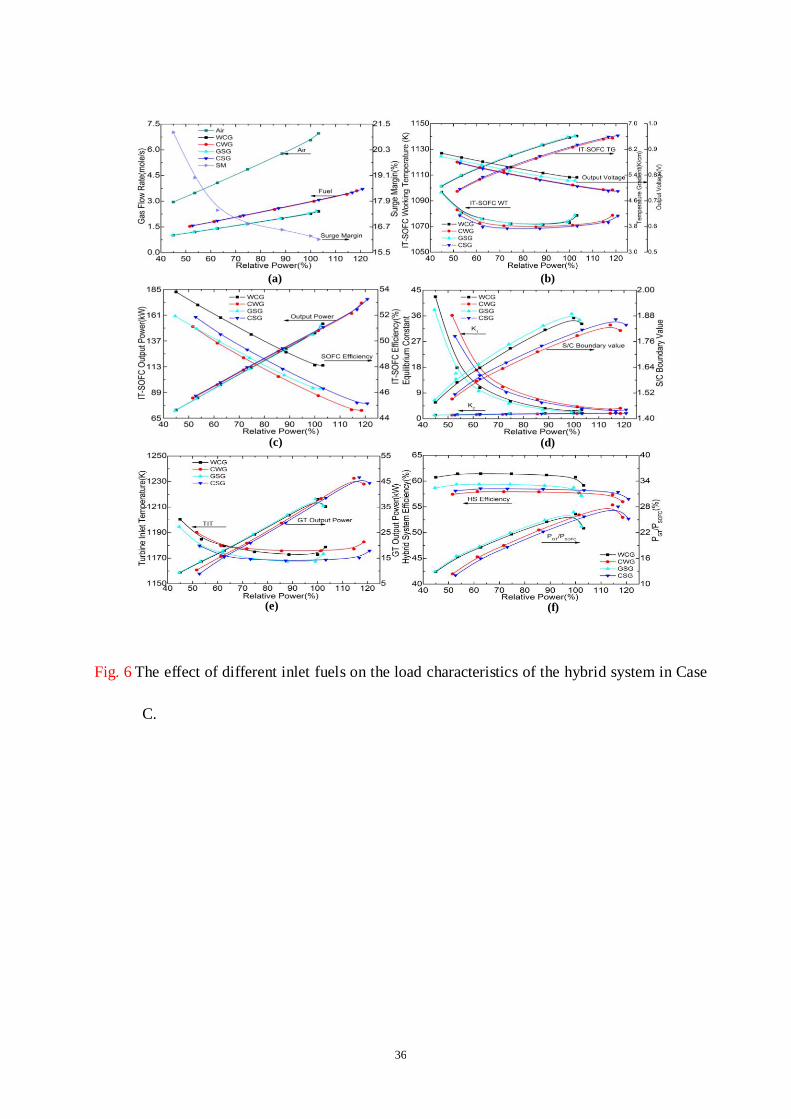
Fig.6 shows the variable load characteristics of the hybrid system in Case C. Fig.6 (a)
illustrates, as the system load rises, both biomass flow and air flow increase linearly but the
compressor SM decreases from 21.12% to 16.12%. This is because, with increasing rotational
speed, airflow, and pressure ratio, the operating point moves up gradually close to the surge line
along β line, causing SM to decline. It can also be seen that, when using WCG and GSG, the
system load varies between 45% and 103% of the rated power, but for other two fuels, the
system load ranges are 51.62%~118.56% and 52.74%~120.84%, respectively.
For a constant Uf, increasing fuel flow can escalate current density, causing more
electrochemical reaction. In this process, the fuel cell working temperature first decreases to the
designed value and then increases, as shown in Fig.6 (b). The fuel cell mean temperature
gradient increases and voltage declines with the increasing system load. When using WCG and
GSG, the fuel cell operating parameters are all higher than those of other two fuels. Fig.6 (c)
shows that with increasing system load, the cell output power rises and the efficiency declines.
With using WCG, the cell efficiency drops from 53.81% to 48.11%, but it is still higher than

18
those of other three fuels. This trend is similar to that in Fig.4 (c). However, for the reforming
characteristics, when using WCG and GSG, K1 declines and K2 rises, S/Cbv reaches a maximum
value at the design point and then declines with increasing system load. For using CWG and
CSG, S/Cbv reaches a maximum value at 115% load condition shown in Fig.6 (d). Meanwhile,
for WCG, K1 is higher than that of GSG, but it is less than those of other two fuels while the
variation trend for S/Cbv is right opposite.
With increasing system load, TIT first decreases to the design value and then increases, the
GT output power reaches a maximum value at the design point and then declines, as shown in
Fig.6 (e). The difference from Cases A and B is that when the system uses CWG as fuel, the
TIT is the highest. It can also be seen that, when the system operates at low load state, the GT
output power is higher than those of other two fuels if WCG and GSG are used. However,
rising system load can greatly increase the GT power of other two fuels, higher than those from
WCG and GSG.
In Fig.6 (f), with increasing system load, the system efficiency has no significant change
until it reaches the designed point, and PGT/PSOFC increases gradually and reaches a maximum
value at the designed point. This is because when the system is in a light load state, low
rotational speed leads the pressure and air flow entering the system to decrease. Thus, the
workability of the turbine through gas expansion is very poor. This phenomenon can also be
observed from Fig.6 (e).
The system power is mainly from the fuel cell (as shown in Fig.6 (c)), achieving a higher
efficiency. However, increasing rotational speed can alter this performance. Both air and

19
pressure rise with higher rotational speed, making the GT generate more power. When the
increasing power level of GT is higher than that of the fuel cell, PGT/PSOFC begins to increase. It
can also be seen that, for using WCG as fuel, the system efficiency is the highest, followed by
GSG, CSG, and CWG successively.
4.4 Analysis and Discussion
In different adjusting modes (Cases A, B and C), component operating characteristics and
system performance can be extensively analyzed by comparing those results in Figs. 4, 5 and 6.
When the system is in variable load operation states, the compressor SM firstly increases
and then decreases in Case A(see Fig.4 (a)), it keeps constant in Case B(see Fig. 5(a)), but it
decreases steadily in Case C (see Fig. 6(a)). More interestingly, when the system operates in
Case A, CSG makes the SM reach 11.69% at system maximum load of 118.90%, which is
below the SM lower threshold of 12% required by Table 3 in [29]. In this case, the air in the
compressor can yield intense pulsation and produce reverse flow, causing the blade to vibrate
and even break. While for using other fuels, the SM is higher than 12%.
Although Case A and Case C make the variation trends of fuel cell working temperature
differently, all voltages drop gradually and mean temperature gradients increase (see Figs. 4(b)
and 6(b)). By contrast, in Case B, the cell voltage rises and the mean temperature gradient
reaches a minimum with increasing system load (see Fig. 5(b)). The reason is that with a
constant air flow rate, small fuel flow causes reformer temperature to be very low and
consequently water gas shift reaction to play a major role. Therefore, heat is released, causing
the reformer outlet temperature to increase, the temperature difference between both ends of the
20
fuel cell to decrease, and ultimately the mean temperature gradient decreases. On the contrary,
with increasing fuel flow, the reformer temperature increases, and CH4 reforming plays a major
role. In this case, heat is absorbed, causing the reformer outlet temperature to decrease and the
temperature difference between both ends of the fuel cell and the mean temperature gradient to
increase. This phenomenon implies that the fell cell inner temperature profile changes sharply
in a variable load operation, which is a great challenge for selecting proper coefficient of
thermal expansion of fuel cell materials.
In Case C, the fuel cell working temperature decreases to the designed value and then
increases with rising system load. It is probably due to that when the fuel-air ratio is constant,
low rotational speed will cause the pressure ratio and airflow entering the system to be very
small, resulting in a decreasing enthalpy drop of adiabatic expansion in the turbine. Hence,
high-temperature exhaust gas entering the system escalates the working temperature of heat
exchanger and evaporator, and finally causes the fuel cell working temperature to increase.
However, with increasing rotational speed, the pressure ratio and air entering the system rise
gradually, and the enthalpy drop of adiabatic expansion in the turbine also increases, leading
the temperature of turbine exhaust gas to decline. The consequence is that the reduction in the
fuel cell working temperature. All three adjusting modes make the cell output power increase
gradually with increasing system load, but the cell efficiency varies significantly. Case A and
Case C cause the cell efficiency to decrease while Case B has an opposite effect on it. More
interestingly, in Case B, the fuel cell outputs higher power when the system using CWG and
CSG as fuel, but in Case C, the fuel cell efficiency can reach a maximum with WCG (see
21
Fig.6(c)).
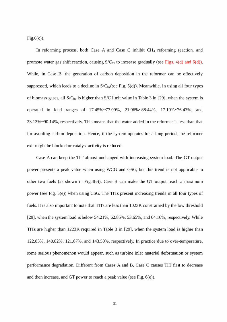
In reforming process, both Case A and Case C inhibit CH4 reforming reaction, and
promote water gas shift reaction, causing S/Cbv to increase gradually (see Figs. 4(d) and 6(d)).
While, in Case B, the generation of carbon deposition in the reformer can be effectively
suppressed, which leads to a decline in S/Cbv(see Fig. 5(d)). Meanwhile, in using all four types
of biomass gases, all S/Cbv is higher than S/C limit value in Table 3 in [29], when the system is
operated in load ranges of 17.45%~77.09%, 21.96%~88.44%, 17.19%~76.43%, and
23.13%~90.14%, respectively. This means that the water added in the reformer is less than that
for avoiding carbon deposition. Hence, if the system operates for a long period, the reformer
exit might be blocked or catalyst activity is reduced.
Case A can keep the TIT almost unchanged with increasing system load. The GT output
power presents a peak value when using WCG and GSG, but this trend is not applicable to
other two fuels (as shown in Fig.4(e)). Case B can make the GT output reach a maximum
power (see Fig. 5(e)) when using CSG. The TITs present increasing trends in all four types of
fuels. It is also important to note that TITs are less than 1023K constrained by the low threshold
[29], when the system load is below 54.21%, 62.85%, 53.65%, and 64.16%, respectively. While
TITs are higher than 1223K required in Table 3 in [29], when the system load is higher than
122.83%, 140.82%, 121.87%, and 143.50%, respectively. In practice due to over-temperature,
some serious phenomenon would appear, such as turbine inlet material deformation or system
performance degradation. Different from Cases A and B, Case C causes TIT first to decrease
and then increase, and GT power to reach a peak value (see Fig. 6(e)).
22
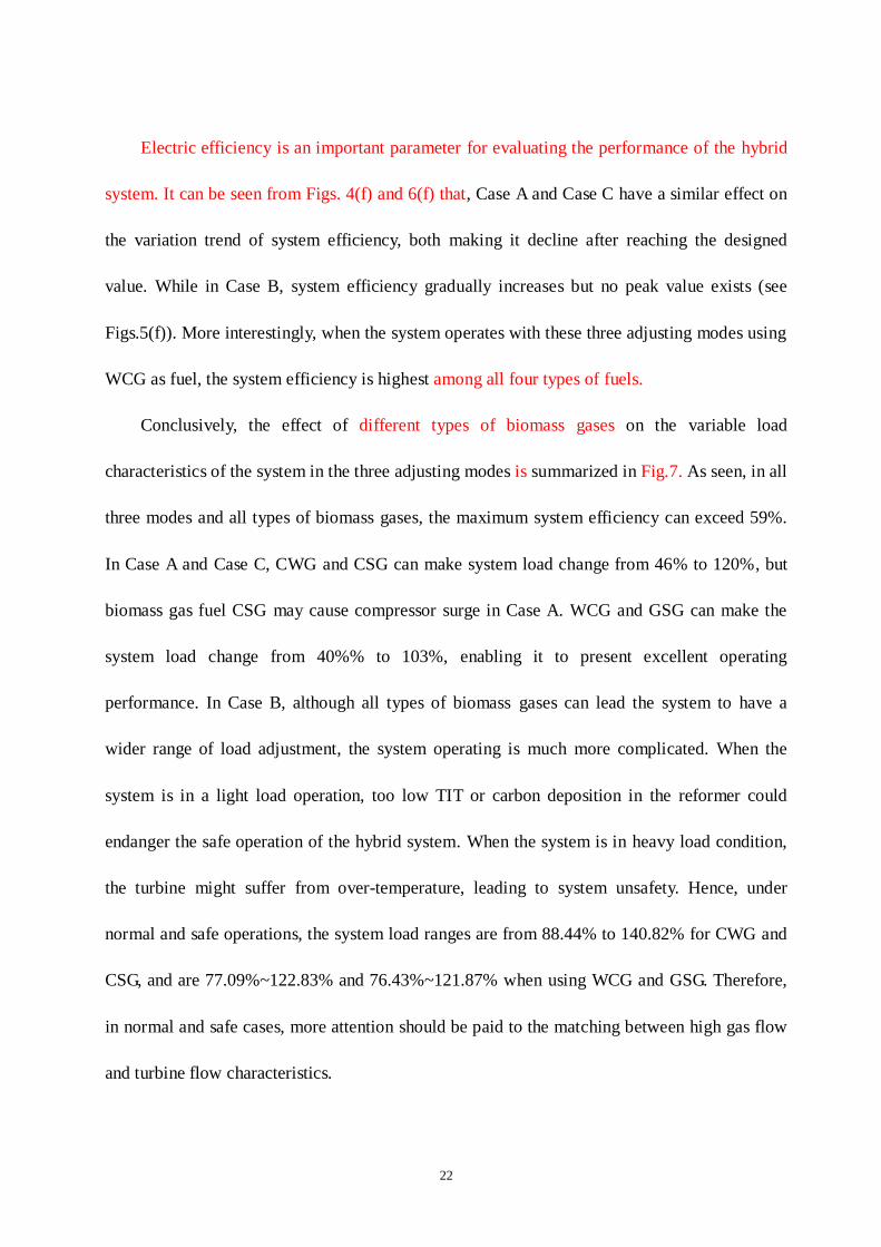
Electric efficiency is an important parameter for evaluating the performance of the hybrid
system. It can be seen from Figs. 4(f) and 6(f) that, Case A and Case C have a similar effect on
the variation trend of system efficiency, both making it decline after reaching the designed
value. While in Case B, system efficiency gradually increases but no peak value exists (see
Figs.5(f)). More interestingly, when the system operates with these three adjusting modes using
WCG as fuel, the system efficiency is highest among all four types of fuels.
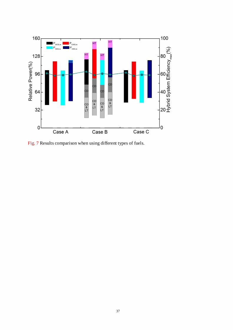
Conclusively, the effect of different types of biomass gases on the variable load
characteristics of the system in the three adjusting modes is summarized in Fig.7. As seen, in all
three modes and all types of biomass gases, the maximum system efficiency can exceed 59%.
In Case A and Case C, CWG and CSG can make system load change from 46% to 120%, but
biomass gas fuel CSG may cause compressor surge in Case A. WCG and GSG can make the
system load change from 40%% to 103%, enabling it to present excellent operating
performance. In Case B, although all types of biomass gases can lead the system to have a
wider range of load adjustment, the system operating is much more complicated. When the
system is in a light load operation, too low TIT or carbon deposition in the reformer could
endanger the safe operation of the hybrid system. When the system is in heavy load condition,
the turbine might suffer from over-temperature, leading to system unsafety. Hence, under
normal and safe operations, the system load ranges are from 88.44% to 140.82% for CWG and
CSG, and are 77.09%~122.83% and 76.43%~121.87% when using WCG and GSG. Therefore,
in normal and safe cases, more attention should be paid to the matching between high gas flow
and turbine flow characteristics.
23
Although the quantitative results are only applicable to the hybrid system established in
this work, the research method and results have a guiding significance for system design and
adjusting mode selection of other similar practical hybrid systems.
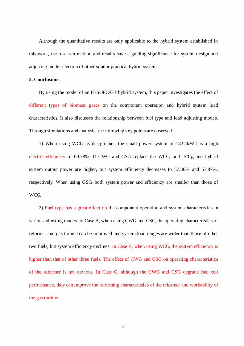
5. Conclusions
By using the model of an IT-SOFC/GT hybrid system, this paper investigates the effect of
different types of biomass gases on the component operation and hybrid system load
characteristics. It also discusses the relationship between fuel type and load adjusting modes.
Through simulations and analysis, the following key points are observed.
1) When using WCG as design fuel, the small power system of 182.4kW has a high
electric efficiency of 60.78%. If CWG and CSG replace the WCG, both S/Cbv and hybrid
system output power are higher, but system efficiency decreases to 57.36% and 57.87%,
respectively. When using GSG, both system power and efficiency are smaller than those of
WCG.
2) Fuel type has a great effect on the component operation and system characteristics in
various adjusting modes. In Case A, when using CWG and CSG, the operating characteristics of
reformer and gas turbine can be improved and system load ranges are wider than those of other
two fuels, but system efficiency declines. In Case B, when using WCG, the system efficiency is
higher than that of other three fuels. The effect of CWG and CSG on operating characteristics
of the reformer is not obvious. In Case C, although the CWG and CSG degrade fuel cell
performance, they can improve the reforming characteristics of the reformer and workability of
the gas turbine.

24
3) Different fuels should be matched with appropriate adjusting modes to ensure that the
system presents excellent performance. With the three load adjusting modes, all types of
biomass gases can make the maximum efficiency of the hybrid system exceed 59%. If a high
efficiency (for example 62.73%) and a wide range of load adjustment are required by users,
Case B is more appropriate with using fuels like WCG and GSG. When users require the
system to have higher efficiency and low load, Case A is more suitable. With fuels like CWG
and CSG, Case C is desirable for good system safety performance and lower load adjusting.

25
6. Acknowledgments
The research is supported by National Natural Science Foundation of China under grant
No.51376123, 863 Program of China (No.2014AA052803) and The Engineering and Physical
Sciences Research Council-EPSRC (EP/M000141/1).
26
7. References
[1] Fuel Cell Handbook. U.S. Department of Energy,Office of Fossil Energy,National Energy
Technology Laboratory, November 2004.
[2] Kaneko T, Brouwer J, Samuelsen G.S. Power and temperature control of fluctuating
biomass gas fueled solid oxide fuel cell and micro gas turbine hybrid system. J Power Source
2006; 160: 316–325.
[3] Bang-Møller C, Rokni M. Thermodynamic performance study of biomass gasification,solid
oxide fuel cell and micro gas turbine hybrid systems. Energy Convers. Manage 2010; 51:
2330-2339.
[4] Bang-Møller C, Rokni M, Elmegaard B. Exergy analysis and optimization of a biomass
gasification, solid oxide fuel cell and micro gas turbine hybrid system. Energy 2011; 36:
4740-4752.
[5] Toonssen R, Aravind P.V, Woudstra N, H.M. Verkooijen A. Alternative system designs of
biomass gasification SOFC/GT hybrid systems. Int J Hydrogen Energy 2011;36:10414-10425.
[6] Karellas S, Karl J, Kakaras E. An innovative biomass gasification process and its coupling
with micro turbine and fuel cell systems. Energy 2008;33:284–291.
[7] Facchinetti E, Gassner M, Favrat D. Process integration and optimization of a solid oxide
fuel cell-gas turbine hybrid cycle fueled with hydrothermally gasified waste biomass. Energy
2012; 41:408-419.
[8] Zhao Y, Sadhukhan J, Lanzini A, Brandon N, Shah N. Optimal integration strategies for a
syngas fuelled SOFC and gas turbine hybrid. J Power Source 2011; 196: 9516-9527.
27
[9] Bakalis D P, Stamatis A G. Incorporating available micro gas turbines and fuel cell:
Matching considerations and performance evaluation. Appl Energy 2013; 103: 607–617.
[10] Zabihian F, Fung A S. Performance analysis of hybrid solid oxide fuel cell and gas turbine
cycle: Application of alternative fuels. Energy Convers. Manage 2013; 76: 571–580.
[11] Sucipta M, Kimijima S. Biomass Solid Oxide Fuel Cell-Microgas Turbine Hybrid System:
Effect of Fuel Composition. J Fuel Cell Sci Tech 2008;5.
[12] Zhang X, Wang Y, Liu T, Chen J. Theoretical basis and performance optimization analysis
of a solid oxide fuel cell-gas turbine hybrid system with fuel reforming. Energy Convers.
Manage 2013; 61:1102–1109.
[13] Marsano F, Magistri L, Bozzolo M, Tarnowski O. Influence of fuel composition on solid
oxide fuel cell hybrid system layout and performance. ASME Turbo Expo 2004: 533-540.
[14] Santin M, Traverso A, Magistri L. Liquid fuel utilization in SOFC hybrid systems. Appl
Energy 2009; 86: 2204-2212.
[15] Santin M, Traverso A, Magistri L, Massardo A. Thermoeconomic analysis of SOFC-GT
hybrid systems fed by liquid fuels. Energy 2010; 35: 1077-1083.
[16] Maréchal F, Leuenberger S, Membrez Y, Bucheli O,Favrat D. Process flow model of solid
oxide fuel cell system supplied with sewage biogas. J Power Sources 2004; 131:127-141.
[17] Zabihian F, Fung A S. Performance analysis of hybrid solid oxide fuel cell and gas turbine
cycle (part I): Effects of fuel composition on output power. J Energy Inst 2014; 87: 18-27.
[18] Zabihian F, Fung A S. Performance analysis of hybrid solid oxide fuel cell and gas turbine
cycle (part II): Effects of fuel composition on specific work and efficiency. J Energy Inst 2014;

28
87: 28-34.
[19] Sucipta M, Kimijima S, Song T W, Suzuki K. Biomass solid oxide fuel cell-microgas
turbine hybrid system: Effect of fuel composition. J Fuel Cell Sci Tech 2008; 5:1-8.
[20] Sucipta M, Kimijima S, Suzuki K. Performance analysis of the SOFC–MGT hybrid
system with gasified biomass fuel. J Power Sources 2007; 174: 124-135.
[21] Rokni M. Thermodynamic analysis of SOFC (solid oxide fuel cell)-Stirling hybrid plants
using alternative fuels. Energy 2013; 61: 87-97.
[22] Harun N F, Tucker D, Adams T A. Fuel Composition Transients in Fuel Cell Turbine
Hybrid for Polygeneration Applications. J Fuel Cell Sci Tech 2014; 11: 1-8.
[23] Fernandes A, Woudstra T, Aravind P V. System simulation and exergy analysis on the use
of biomass-derived liquid-hydrogen for SOFC/GT powered aircraft. Int J Hydrogen Energy
2015; 40: 4683-4697.
[24] Ma S, Wang J, Yan Z, Dai Y, Lu B. Thermodynamic analysis of a new combined cooling,
heat and power system driven by solid oxide fuel cell based on ammonia–water mixture. J
Power Sources 2011; 196: 8463-8471.
[25] Caliandro P, Tock L, Ensinas A V, Marechal F. Thermo-economic optimization of a solid
oxide fuel cell-gas turbine system fuelled with gasified lignocellulosic biomass. Energy
Convers. Manage 2014; 85: 764-773.
[26] Li Y,Weng Y. Performance study of a solid oxide fuel cell and gas turbine hybrid system
designed for methane operating with non-designed fuels. J Power Source 2011;196 ;3824-3835.
[27] Milewski J, Miller A, Sałaci´nski J. Off-design analysis of SOFC hybrid system. Int J
29
Hydrogen Energy 2007; 32: 687 – 698.
[28] Calise F, Palombo A, Vanoli L. Design and partial load exergy analysis of hybrid
SOFC-GT power plant. J Power Source 2006.;158:225–244.
[29] Lv X, Weng Y. Effect of operating parameters on a hybrid system of
intermediate-temperature solid oxide fuel cell and gas turbine. Energy 2015; 91: 10-19.
[30] Lv X, Weng Y. Safety Analysis of a SOFC/GT Hybrid System Fueled With Gasified
Biomass. J Fuel Cell Sci Tech 2015;12:011008-1-011008-6.
[31] Aguiar P, Adjiman C S, Brandon N P. Anode supported intermediate temperature direct
internal reforming solid oxide fuel cell. I: Model-based steady-state performance. J Power
Source 2004.;138:120-136.
[32] Wang Y, Yoshiba F, Kawase M, Watanabe T. Performance and effective kinetic models of
methane steam reforming over Ni/YSZ anode of planar SOFC. Int J Hydrogen Energy 2009;34:
3885-3893.
[33] Liu A, Weng Y. Performance analysis of a pressurized molten carbonate fuel
cell/micro-gas turbine hybrid system. J Power Source 2010;195: 204–213.
[34] Yao Z, Weng Y. Characteristic analysis of a fuel cell and gas turbine hybrid system
utilizing biomass syngas[D]. Shanghai Jiao Tong University. 2012( In Chinese ).
[35] Barelli L, Bidini G, Ottaviano A. Part load operation of SOFC/GT hybrid systems:
Stationary analysis. Int. J Hydrogen Energy 2012; 37: 16140-16150.
[36] Komatsu Y, Kimijima S, Szmyd J.S. Performance analysis for the part-load operation of a
solid oxide fuel cell-micro gas turbine hybrid system. Energy 2010; 35; 982–988.

30
[37] Yin. J, Weng Y, Su S. Investigation on performance of a lean-burn catalytic combustion
micro gas turbine system[D]. Shanghai Jiao Tong University PhD. 2010( In Chinese ).
[38] Liu A, Weng Y. Numerical simulation of fuel cells/gas turbine hybrid power system and
catalytic combustion experiment study[D]. Shanghai Jiao Tong University PhD. 2009( In
Chinese ).
[39] Li Y,Weng Y. Off-design analysis and experiment study of high temperature fuel cell/gas
turbine hybrid system[D]. Shanghai Jiao Tong University PhD. 2011( In Chinese ).
31
8. Nomenclature
Nomenclature
M mole flow rate(kg s-1)
ni composition i mole flow rate(mol s-1)
K1 CH4 reforming reaction equilibrium constant
K2 water gas shift reaction equilibrium constant
LHV lower heating value(kJ mol-1)
PSOFC SOFC output power(kW)
PT turbine output power(kW)
PC,air air compressor consumption power(kW)
PC,fuel fuel compressor consumption power(kW)
PP,air water syringe pump consumption power(kW)
ηDC/AC DC/AC inverter efficiency (%)
ηg electric generator(%)
ηm GT mechanical efficiency (%)
ηe electric motor efficiency(%)
yi composition i mole fraction(%)
x CH4 consumption mole in reforming reaction
y CO consumption mole in reforming reaction
Uf fuel utilization
S/C ratio of steam to CH4, CO, and CO2
S/Cbv boundary value of the S/C ratio
Abbreviation
TIT turbine inlet temperature
SM surge margin
GT gas turbine
IT-SOFC intermediate-temperature solid oxide fuel cell
MTG mean temperature gradient
WCG wood chip gas
CWG cotton wood gas
GSG grape seed gas
CSG corn stalk gas
CC catalytic combustor
HE heat exchanger
CD carbon deposition
HT higher temperature
LT lower temperature
32
Figure Caption List:
TC
Air
C C
Biomass Gas
Water Exhaust Gas
1
2
3
4
5
67
89
10
11 12 13
14
Catalytic
Combustor
Gas Turbine
Heat Exchange 1
Mixer
Evaporator
V 1
V 2Power
Power
IT-SOFC
DC
AC
ReformerFuel Compressor
Water Pump
Heat Exchange 2
Generator
1516
17
1819
V 3
Fig. 1 The schematic of the IT-SOFC/GT hybrid system.
33
Start
System Assumption
Parameter Initialization
,π,T0,P01/N T
Characteristic Map
, Pc,T2,P2c
Fuel
Mixer
PM,out,TM,out,mM,out,ni,out,
Water
Reformer
IT-SOFC Stack
maxminw ,TTT
Y
N
Exhaust
maxmin3 ,TTT
,T3,P3,
Characteristic Map
, P4,T4,Pt,
3/N T
t
Y
N
Matching and Calculation
Convergence
Y N
Output
Turbine
Air Compressur
HE 1
Heat Transfer Process
Pfuel,out,Tfuel,out,mfuel,out
Fuel Compressur
Pwater,out,Twater,out,mwater,out
Syringe Pump
Evaporator
Psteam,out,Tsteam,out,msteam,out
Pref,out,Tref,out,mref,out,ni,out,K1,
K2,S/Cbv
HE 2
Heat Transfer Process
Pcell,out,Tcell,out,mcell,out,ni,out,TGcell,
V, PSOFC,
?
Pressure Drops
Calculation
cell
N
Catalytic Combustor
Pcom,out,Tcom,out,mcom,out,ni,out,
?P
ara
met
er I
nit
iali
zati
on
Ad
just
men
t
Air
Hybrid System
Power/Efficiency
Fig. 2 Circulation flowchart of the IT-SOFC/GT.

34
Fig. 3 Gas turbine operating trajectory map.
(c) (d)
(e) (f)
(a) (b)
35
Fig. 4 The effect of different inlet fuels on the load characteristics of the hybrid system in Case
A.
Fig. 5 The effect of different inlet fuels on the load characteristics of the hybrid system in Case
B.
(a) (b)
(c) (d)
(e) (f)
36
Fig. 6 The effect of different inlet fuels on the load characteristics of the hybrid system in Case
C.
(a) (b)
(c) (d)
(e) (f)
37
Fig. 7 Results comparison when using different types of fuels.
38
Table Caption List:
Table. 1 Composition and lower heating value of different gasified biomass.
Table. 2 Performance of the IT-SOFC/GT Hybrid system.
Type WCG Uf=75% CWG Uf=60% GSG Uf=75% CSG Uf=60%
Fuel flow rate/mol/s 2.269 3.403 2.28 3.502
IT-SOFC current density/ A/m2 5000 6000 5025 6175
IT-SOFC working temperature/K 1073 1073 1073 1073
IT-SOFC MTG/ K/cm 6.571 6.518 6.581 6.592
S/C boundary value 1.87 1.84 1.89 1.86
IT-SOFC voltage/V 0.79 0.74 0.78 0.74
IT-SOFC power/kW 144.4 162.6 142.7 166.2
TIT /K 1173 1171 1167 1170
Gas flow rate/ kg/s 0.2747 0.3251 0.2794 0.3293
GT power/kW 38.01 46.28 38.19 46.62
Air compressor consumption/kW 27.48 27.48 27.48 27.48
Fuel compressor consumption/kW 7.929 13.1 8.3 13.51
Syringe pump consumption /kW 0.012 0.018 0.013 0.019
Hybrid system power/kW 182.4 208.9 180.9 212.9
Hybrid System efficiency/% 60.78 57.36 58.74 57.87
Type CH4[%] H2[%] CO[%] CO2[%] N2[%] CnHm[%] LHV[MJ/Nm3]
WCG 4.34 23.03 15.04 17.75 39.81 0.00 7.79
CSG 1.90 12.20 21.40 13.00 51.50 0.00 5.33
CWG 1.90 11.50 22.70 11.60 51.30 1.00 5.39
GSG 4.00 17.00 22.00 13.00 42.00 2.00 7.41


![DURABILITY OF FUEL PUMPS AND FUEL LEVEL ... … 664 [AVFL-15a]/AVFL... · DURABILITY OF FUEL PUMPS AND FUEL LEVEL ... Fuel pump soak data ... fuel pumps and fuel level senders were](https://img.pdfslide.us/doc/110x75/5b5fc9d67f8b9a51328e7dbf/durability-of-fuel-pumps-and-fuel-level-664-avfl-15aavfl-durability.jpg)