Embed Size (px)
Citation preview
Open Journal of Fluid Dynamics, 2017, 7, 462-474 http://www.scirp.org/journal/ojfd
ISSN Online: 2165-3860 ISSN Print: 2165-3852
DOI: 10.4236/ojfd.2017.73031 Sep. 29, 2017 462 Open Journal of Fluid Dynamics
Effect of Double Air Injection on Instability Phenomena in Centrifugal Compressor
Toshiyuki Hirano1, Tatsuya Ogawa2, Hoshio Tsujita3
1Mechanical Engineering Course, Department of Science and Engineering, Kokushikan University, Tokyo, Japan 2Graduate School of Engineering, Program in Mechanical Engineering, Kokushikan University, Tokyo, Japan 3Department of Mechanical Engineering, Faculty of Science and Engineering, Hosei University, Tokyo, Japan
Abstract In the operation of a centrifugal compressor of turbocharger, instability phe-nomena such as rotating stall and surge are induced at a lower flow rate close to the maximum pressure ratio. In this study, the compressed air at the exit of centrifugal compressor was re-circulated and injected to the impeller inlet by using two injection nozzles in order to suppress the surge phenomenon. The most effective circumferential position was examined to reduce the flow rate at the surge inception. Moreover, the influences of the injection on the fluc-tuating property of the flow field before and after the surge inception were investigated by examining the frequency of static pressure fluctuation on the wall surface and visualizing the compressor wall surface by oil-film visualiza-tion technique.
Keywords Centrifugal Compressor, Performance, Nozzle Injection, Surge
1. Introduction
In recent years, the regulations of the exhaust gas and the fuel consumption of automobile become more severe with the years from the viewpoint of global warming prevention. In Europe, the technology termed the supercharged down-sizing is developing and regarded as a part for environmental regulations, in which the displacement reduced by the downsizing of engine aiming to minim-ize its mechanical loss is supplemented by the equipment of a turbocharger for the engine to keep the torque. Therefore, the application of a turbocharger to various types of vehicle is developing rapidly. On the other hand, the centrifugal compressor, which is a main component of turbocharger, possesses higher pres-
How to cite this paper: Hirano, T., Ogawa, T. and Tsujita, H. (2017) Effect of Double Air Injection on Instability Phenomena in Centrifugal Compressor. Open Journal of Fluid Dynamics, 7, 462-474. https://doi.org/10.4236/ojfd.2017.73031 Received: July 25, 2017 Accepted: September 26, 2017 Published: September 29, 2017 Copyright © 2017 by authors and Scientific Research Publishing Inc. This work is licensed under the Creative Commons Attribution International License (CC BY 4.0). http://creativecommons.org/licenses/by/4.0/
Open Access
T. Hirano et al.
DOI: 10.4236/ojfd.2017.73031 463 Open Journal of Fluid Dynamics
sure ratio in a single stage than that of axial one. But, the performance of com-pressors at lower flow rate is characterized by the occurrence of unsteady flow phenomena such as surge and rotating stall. Such instabilities cause critical op-erating conditions with strong dynamical loading on the blades and can there-fore not be tolerated during compressor operation. The surge may generate enough intense vibration and noise to destroy the whole pipeline system includ-ing a compressor. As a result, the stable operation range is inevitably restricted. Therefore, the extension of the stable operation range and the improvement of the supercharging characteristics of a centrifugal compressor are required dra-matically. Several investigations [1]-[9] have been carried out to control the in-ception of instability phenomena for the purpose of the extension of stable oper-ation range of a centrifugal compressor to the lower flow rate. However, the fac-tors leading to the occurrence of surge have not been clarified yet.
In this study, the compressed air at the exit of centrifugal compressor was re-circulated and injected to the impeller inlet by using two injection nozzles in order to suppress the surge phenomenon. In addition, the optimum circumfe-rential relative position of two injection nozzles, which most effectively reduced the flow rate for the surge inception, was investigated for the compressor at rota-tional speed of 40,000 rpm. Moreover, the influences of the injection on the fluctuating property of the flow field before and after the surge inception were investigated by examining the frequency of static pressure fluctuation on the wall surface and visualizing the compressor wall surface by oil-film visualization technique.
2. Experimental Apparatus and Method
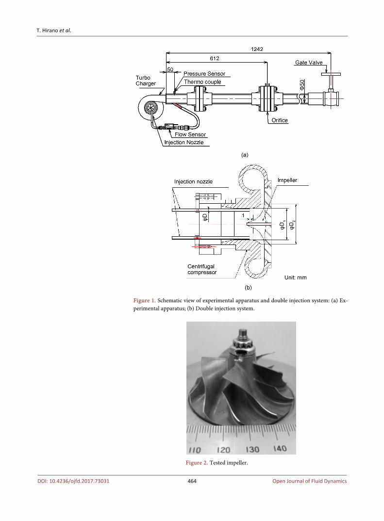
The experimental apparatus used in this study is shown in Figure 1(a). The compressed air supplied from the screw compressor was used to drive the tur-bine impeller which revolved the compressor impeller through the co-rotating axis. In this study, in order to extend the stable operating range of centrifugal compressor to lower flow rate by the suppression of surge phenomenon, a part of the compressed air at the exit of the compressor scroll was re-circulated and injected into the impeller inlet through the bypass pipe by using the double in-jection nozzle system, which consists of two nozzles installed on the inner wall of suction pipe. Figure 1(b) shows the cross-sectional view of double injection sys-tem. The head of each nozzle was installed at 1 mm upstream of the impeller leading edge.
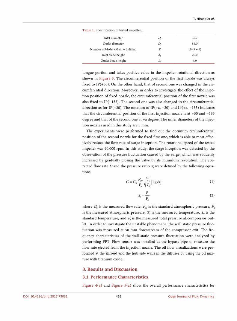
Then, the remaining air at the exit of the compressor scroll was discharged through the delivery duct. In the following, the case with the injection nozzle is named “Injection” and that without the injection nozzle is named “Normal”. The specifications and the configurations of centrifugal impeller are shown in Table 1 and Figure 2, respectively. The injection nozzle is movable in the cir-cumferential direction. The circumferential position of injection nozzles is indi-cated by IP, which has the origin at the corresponding position to the scroll
T. Hirano et al.
DOI: 10.4236/ojfd.2017.73031 464 Open Journal of Fluid Dynamics
Figure 1. Schematic view of experimental apparatus and double injection system: (a) Ex-perimental apparatus; (b) Double injection system.
Figure 2. Tested impeller.
T. Hirano et al.
DOI: 10.4236/ojfd.2017.73031 465 Open Journal of Fluid Dynamics
Table 1. Specification of tested impeller.
Inlet diameter D1 37.7
Outlet diameter D2 52.0
Number of blades (Main + Splitter) Z 10 (5 + 5)
Inlet blade height b1 20.0
Outlet blade height b2 4.0
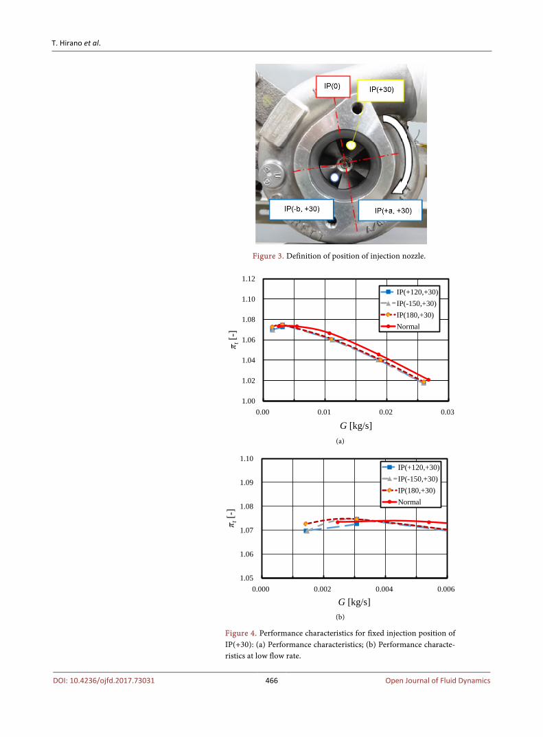
tongue portion and takes positive value in the impeller rotational direction as shown in Figure 3. The circumferential position of the first nozzle was always fixed to IP(+30). On the other hand, that of second one was changed in the cir-cumferential direction. Moreover, in order to investigate the effect of the injec-tion position of fixed nozzle, the circumferential position of the first nozzle was also fixed to IP(−135). The second one was also changed in the circumferential direction as for IP(+30). The notation of IP(+a, +30) and IP(+a, −135) indicates that the circumferential position of the first injection nozzle is at +30 and −135 degree and that of the second one at +a degree. The inner diameters of the injec-tion nozzles used in this study are 5 mm.
The experiments were performed to find out the optimum circumferential position of the second nozzle for the fixed first one, which is able to most effec-tively reduce the flow rate of surge inception. The rotational speed of the tested impeller was 40,000 rpm. In this study, the surge inception was detected by the observation of the pressure fluctuation caused by the surge, which was suddenly increased by gradually closing the valve by its minimum revolution. The cor-rected flow rate G and the pressure ratio πt were defined by the following equa-tions:
[ ]0 10
0
kg sa
a
P TG GP T
= (1)
tt
a
PP
π = (2)
where G0 is the measured flow rate, Pa0 is the standard atmospheric pressure, Pa is the measured atmospheric pressure, T1 is the measured temperature, T0 is the standard temperature, and Pt is the measured total pressure at compressor out-let. In order to investigate the unstable phenomena, the wall static pressure fluc-tuation was measured at 50 mm downstream of the compressor exit. The fre-quency characteristics of the wall static pressure fluctuation were analyzed by performing FFT. Flow sensor was installed at the bypass pipe to measure the flow rate ejected from the injection nozzle. The oil flow visualizations were per-formed at the shroud and the hub side walls in the diffuser by using the oil mix-ture with titanium oxide.
3. Results and Discussion 3.1. Performance Characteristics
Figure 4(a) and Figure 5(a) show the overall performance characteristics for
T. Hirano et al.
DOI: 10.4236/ojfd.2017.73031 466 Open Journal of Fluid Dynamics
Figure 3. Definition of position of injection nozzle.
(a)
(b)
Figure 4. Performance characteristics for fixed injection position of IP(+30): (a) Performance characteristics; (b) Performance characte-ristics at low flow rate.
1.00
1.02
1.04
1.06
1.08
1.10
1.12
0.00 0.01 0.02 0.03
π t[-
]
G [kg/s]
IP(+120,+30)IP(-150,+30)IP(180,+30)Normal
1.05
1.06
1.07
1.08
1.09
1.10
0.000 0.002 0.004 0.006
π t[-
]
G [kg/s]
IP(+120,+30)IP(-150,+30)IP(180,+30)Normal
T. Hirano et al.
DOI: 10.4236/ojfd.2017.73031 467 Open Journal of Fluid Dynamics
(a)
(b)
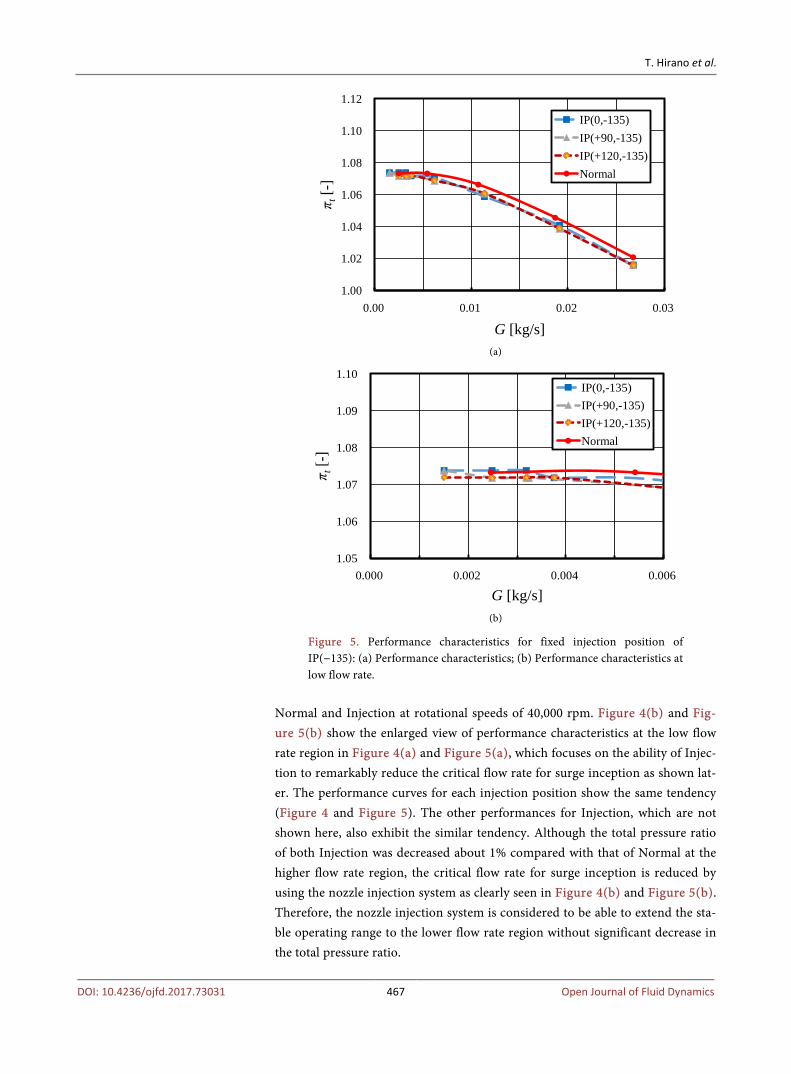
Figure 5. Performance characteristics for fixed injection position of IP(−135): (a) Performance characteristics; (b) Performance characteristics at low flow rate.
Normal and Injection at rotational speeds of 40,000 rpm. Figure 4(b) and Fig-ure 5(b) show the enlarged view of performance characteristics at the low flow rate region in Figure 4(a) and Figure 5(a), which focuses on the ability of Injec-tion to remarkably reduce the critical flow rate for surge inception as shown lat-er. The performance curves for each injection position show the same tendency (Figure 4 and Figure 5). The other performances for Injection, which are not shown here, also exhibit the similar tendency. Although the total pressure ratio of both Injection was decreased about 1% compared with that of Normal at the higher flow rate region, the critical flow rate for surge inception is reduced by using the nozzle injection system as clearly seen in Figure 4(b) and Figure 5(b). Therefore, the nozzle injection system is considered to be able to extend the sta-ble operating range to the lower flow rate region without significant decrease in the total pressure ratio.
1.00
1.02
1.04
1.06
1.08
1.10
1.12
0.00 0.01 0.02 0.03 π t
[-]
G [kg/s]
IP(0,-135)IP(+90,-135)IP(+120,-135)Normal
1.05
1.06
1.07
1.08
1.09
1.10
0.000 0.002 0.004 0.006
π t[-]
G [kg/s]
IP(0,-135)IP(+90,-135)IP(+120,-135)Normal
T. Hirano et al.
DOI: 10.4236/ojfd.2017.73031 468 Open Journal of Fluid Dynamics
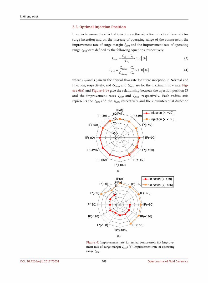
3.2. Optimal Injection Position
In order to assess the effect of injection on the reduction of critical flow rate for surge inception and on the increase of operating range of the compressor, the improvement rate of surge margin IRSM and the improvement rate of operating range IROR were defined by the following equations, respectively:
[ ]100 %N IRSM
N
G GIG−
= × (3)
[ ]max
max
100 %I IROR
N N
G GIG G
−= ×
− (4)
where GN and GI mean the critical flow rate for surge inception in Normal and Injection, respectively, and GNmax and GImax are for the maximum flow rate. Fig-ure 6(a) and Figure 6(b) give the relationship between the injection position IP and the improvement rates IRSM and IROR, respectively. Each radius axis represents the IRSM and the IROR, respectively and the circumferential direction
(a)
(b)
Figure 6. Improvement rate for tested compressor: (a) Improve-ment rate of surge margin IRSM; (b) Improvement rate of operating range IROR.
T. Hirano et al.
DOI: 10.4236/ojfd.2017.73031 469 Open Journal of Fluid Dynamics
indicates the injection position. The measurements for IP(0,+30), IP(+30, +30), IP(+60, +30), IP(+180, −135), IP(−150, −135), IP(−120, −135) and IP(−90, −135) could not be performed because the holders of two injection nozzles interfered with each other at these region of injection positions. The IRSM exhibits the im-provement rate of about 40% for every IP. The effect of the difference in the po-sition of the fixed nozzle on IRSM was not observed. In the previous study [9], however, the effects of IP on IRSM were detected. The critical flow rate for surge inception of Normal in this study was lower than that in the previous study. Therefore, the dependency of IP on IRSM is considered to be reduced by the de-crease of the critical flow rate for surge inception of Normal. In Figure 6(b), the both of IROR for each fixed nozzle indicate the extension of the operating range compared with that of Normal. The IROR for the fixed nozzle of IP(−135) exhibits the improvement rate of about 3% more than that for the fixed nozzle of IP(−135) for every IP. However, IRSM of IP(+30) is slightly larger than that of IP(−135). Therefore, it is considered that there is the trade-off between IRSM and IROR caused by the differences in the position of the fixed nozzle. These results suggest that the present double nozzle injection system extends the stable oper-ating range of the compressor to the lower flow rate without significant decrease in the maximum flow rate as well as in the total pressure ratio.
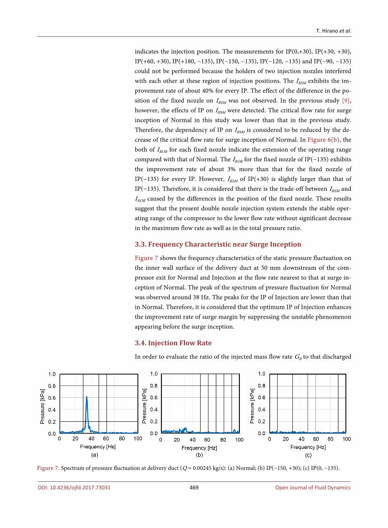
3.3. Frequency Characteristic near Surge Inception
Figure 7 shows the frequency characteristics of the static pressure fluctuation on the inner wall surface of the delivery duct at 50 mm downstream of the com-pressor exit for Normal and Injection at the flow rate nearest to that at surge in-ception of Normal. The peak of the spectrum of pressure fluctuation for Normal was observed around 38 Hz. The peaks for the IP of Injection are lower than that in Normal. Therefore, it is considered that the optimum IP of Injection enhances the improvement rate of surge margin by suppressing the unstable phenomenon appearing before the surge inception.
3.4. Injection Flow Rate
In order to evaluate the ratio of the injected mass flow rate GR to that discharged
Figure 7. Spectrum of pressure fluctuation at delivery duct (Q = 0.00245 kg/s): (a) Normal; (b) IP(−150, +30); (c) IP(0, −135).
T. Hirano et al.
DOI: 10.4236/ojfd.2017.73031 470 Open Journal of Fluid Dynamics
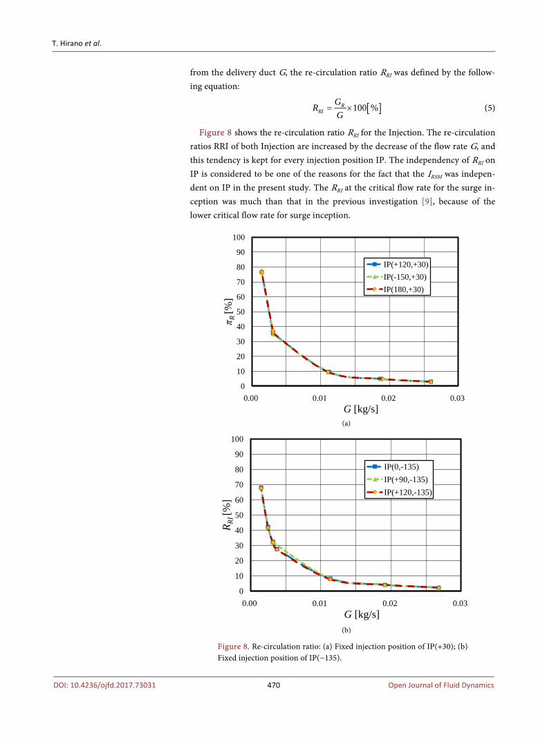
from the delivery duct G, the re-circulation ratio RRI was defined by the follow-ing equation:
[ ]100 %RRI
GRG
= × (5)
Figure 8 shows the re-circulation ratio RRI for the Injection. The re-circulation ratios RRI of both Injection are increased by the decrease of the flow rate G, and this tendency is kept for every injection position IP. The independency of RRI on IP is considered to be one of the reasons for the fact that the IRSM was indepen-dent on IP in the present study. The RRI at the critical flow rate for the surge in-ception was much than that in the previous investigation [9], because of the lower critical flow rate for surge inception.
(a)
(b)
Figure 8. Re-circulation ratio: (a) Fixed injection position of IP(+30); (b) Fixed injection position of IP(−135).
0
10
20
30
40
50
60
70
80
90
100
0.00 0.01 0.02 0.03
π R [%
]
G [kg/s]
IP(+120,+30)IP(-150,+30)IP(180,+30)
0
10
20
30
40
50
60
70
80
90
100
0.00 0.01 0.02 0.03
R RI [
%]
G [kg/s]
IP(0,-135)IP(+90,-135)IP(+120,-135)
T. Hirano et al.
DOI: 10.4236/ojfd.2017.73031 471 Open Journal of Fluid Dynamics
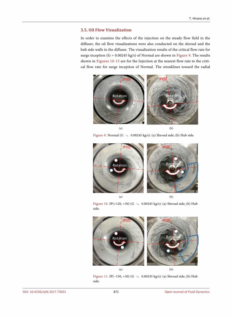
3.5. Oil Flow Visualization
In order to examine the effects of the injection on the steady flow field in the diffuser, the oil flow visualizations were also conducted on the shroud and the hub side walls in the diffuser. The visualization results of the critical flow rate for surge inception (G = 0.00245 kg/s) of Normal are shown in Figure 9. The results shown in Figures 10-15 are for the Injection at the nearest flow rate to the criti-cal flow rate for surge inception of Normal. The streaklines toward the radial
(a) (b)
Figure 9. Normal (G 0.00245 kg/s): (a) Shroud side; (b) Hub side.
(a) (b)
Figure 10. IP(+120, +30) (G 0.00245 kg/s): (a) Shroud side; (b) Hub side.
(a) (b)
Figure 11. IP(−150, +30) (G 0.00245 kg/s): (a) Shroud side; (b) Hub side.
T. Hirano et al.
DOI: 10.4236/ojfd.2017.73031 472 Open Journal of Fluid Dynamics
(a) (b)
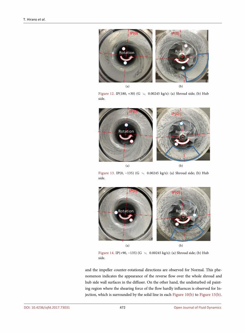
Figure 12. IP(180, +30) (G 0.00245 kg/s): (a) Shroud side; (b) Hub side.
(a) (b)
Figure 13. IP(0, −135) (G 0.00245 kg/s): (a) Shroud side; (b) Hub side.
(a) (b)
Figure 14. IP(+90, −135) (G 0.00245 kg/s): (a) Shroud side; (b) Hub side.
and the impeller counter-rotational directions are observed for Normal. This phe-nomenon indicates the appearance of the reverse flow over the whole shroud and hub side wall surfaces in the diffuser. On the other hand, the undisturbed oil paint-ing region where the shearing force of the flow hardly influences is observed for In-jection, which is surrounded by the solid line in each Figure 10(b) to Figure 15(b).
T. Hirano et al.
DOI: 10.4236/ojfd.2017.73031 473 Open Journal of Fluid Dynamics
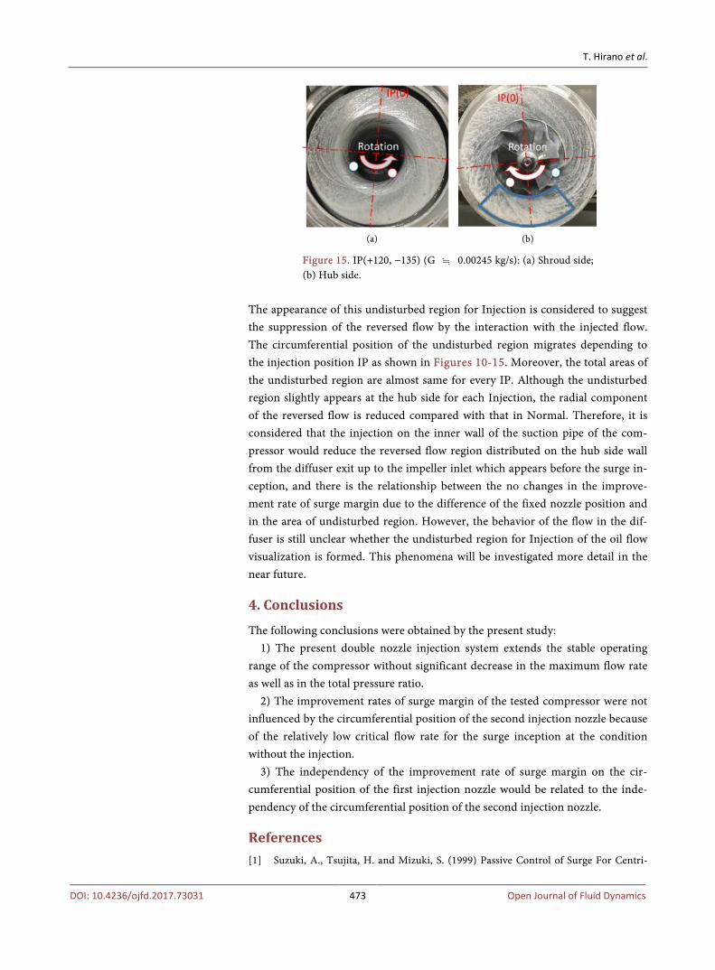
(a) (b)
Figure 15. IP(+120, −135) (G 0.00245 kg/s): (a) Shroud side; (b) Hub side.
The appearance of this undisturbed region for Injection is considered to suggest the suppression of the reversed flow by the interaction with the injected flow. The circumferential position of the undisturbed region migrates depending to the injection position IP as shown in Figures 10-15. Moreover, the total areas of the undisturbed region are almost same for every IP. Although the undisturbed region slightly appears at the hub side for each Injection, the radial component of the reversed flow is reduced compared with that in Normal. Therefore, it is considered that the injection on the inner wall of the suction pipe of the com-pressor would reduce the reversed flow region distributed on the hub side wall from the diffuser exit up to the impeller inlet which appears before the surge in-ception, and there is the relationship between the no changes in the improve-ment rate of surge margin due to the difference of the fixed nozzle position and in the area of undisturbed region. However, the behavior of the flow in the dif-fuser is still unclear whether the undisturbed region for Injection of the oil flow visualization is formed. This phenomena will be investigated more detail in the near future.
4. Conclusions
The following conclusions were obtained by the present study: 1) The present double nozzle injection system extends the stable operating
range of the compressor without significant decrease in the maximum flow rate as well as in the total pressure ratio.
2) The improvement rates of surge margin of the tested compressor were not influenced by the circumferential position of the second injection nozzle because of the relatively low critical flow rate for the surge inception at the condition without the injection.
3) The independency of the improvement rate of surge margin on the cir-cumferential position of the first injection nozzle would be related to the inde-pendency of the circumferential position of the second injection nozzle.
References [1] Suzuki, A., Tsujita, H. and Mizuki, S. (1999) Passive Control of Surge For Centri-
T. Hirano et al.
DOI: 10.4236/ojfd.2017.73031 474 Open Journal of Fluid Dynamics
fugal Compressor by Using Resonator, Proceedings of the Fourth International Symposium on Experimental and Computational Aerothermodynamics of Internal Flows, 2, 226-233.
[2] Mizuki, S., Tsujita, H. and Hishinuma, Y. (2000) Control of Surge for Centrifugal Compression System by Using a Bouncing Ball. ASME Turbo Expo 2000: Power for Land, Sea, and Air, Munich, 8-11 May 2000, Paper No. 2000-GT-0429, V001T03A005. https://doi.org/10.1115/2000-GT-0429
[3] Willemas, F. and De Jager, B. (2000) One-Sided Control of Surge in A Centrifugal Compressor System. ASME Turbo Expo 2000: Power for Land, Sea, and Air, Mu-nich, 8-11 May 2000, Paper 2000-GT-0527, V001T03A091. https://doi.org/10.1115/2000-GT-0527
[4] Skoch, G.J. (2004) Experimental Investigation of Diffuser Hub Injection to Improve Centrifugal Compressor Stability. ASME Turbo Expo 2004: Power for Land, Sea, and Air, Vienna, 14-17 June 2004, Paper No. GT2004-53618, 793-804. https://doi.org/10.1115/GT2004-53618
[5] Tamaki, H., Zheng, X. and Zhang Y. (2012) Experimental Investigation of High Pressure Ratio Centrifugal Compressor with Axisymmetric and Non-Axisymmetric Recirculation Device. ASME Turbo Expo 2012: Turbine Technical Conference and Exposition, Copenhagen, 11-15 June 2012, Paper No. GT2012-68219, 569-581. https://doi.org/10.1115/GT2012-68219
[6] Chen, H. and Lei, V. (2013) Casing Treatment and Inlet Swirl of Centrifugal Com-pressors. Journal of Turbomachinery, 135, Article ID: 041010. https://doi.org/10.1115/1.4007739
[7] Gu, R. and Yashiro, M. (2005) Surge Control for Centrifugal Compressor of Tur-bocharger. JSAE Paper, 36, 83-88.
[8] Gu, R., Mizuki, S., Tsujita, H. and Ikeda, S. (2007) Surge Control of Centrifugal Compressor by Inducer Tip Injection. Proceedings of IGTC2007, Tokyo, 2-7 De-cember 2007, TS-030.
[9] Hirano, T., Takano, M. and Tsujita, H. (2015) Effect of Double Air Injection on Performance Characteristics of Centrifugal Compressor. Journal of Thermal Science, 24, 10-16. https://doi.org/10.1007/s11630-015-0749-3
Submit or recommend next manuscript to SCIRP and we will provide best service for you:
Accepting pre-submission inquiries through Email, Facebook, LinkedIn, Twitter, etc. A wide selection of journals (inclusive of 9 subjects, more than 200 journals) Providing 24-hour high-quality service User-friendly online submission system Fair and swift peer-review system Efficient typesetting and proofreading procedure Display of the result of downloads and visits, as well as the number of cited articles Maximum dissemination of your research work
Submit your manuscript at: http://papersubmission.scirp.org/ Or contact [email protected]