Embed Size (px)
Citation preview
EFFECT OF CUTTING SPEED AND DEPTH OF
CUT ON SURFACE ROUGHNESS OF MILD
STEEL IN TURNING OPERATION
SHEILA THIEN NGA TING
BACHELOR OF ENGINEERING
UNIVERSITI MALAYSIA PAHANG
ii
SUPERVISOR’S DECLARATION
We hereby declare that we have checked this project and in our opinion, this project is
adequate in terms of scope and quality for the award of the degree of Bachelor of
Mechanical Engineering with Manufacturing Engineering.
Signature:
Name of Supervisor: MADAM SALWANI BINTI MOHD SALLEH
Position: LECTURER
Date: 20 NOVEMBER 2009
Signature:
Name of Co-supervisor: MR. LEE GIOK CHUI
Position: LECTURER
Date: 20 NOVEMBER 2009

iii
STUDENT’S DECLARATION
I hereby declare that the work in this project is my own except for quotations and
summaries which have been duly acknowledged. The project has not been accepted for any
degree and is not concurrently submitted for award of other degree.
Signature:
Name: SHEILA THIEN NGA TING
ID Number: ME 06026
Date: 20 NOVEMBER 2009

iv
ACKNOWLEDGEMENTS
I would like to express profound gratitude to my supervisor, Mdm. Salwani Binti
Mohd Salleh for her invaluable support, encouragement, supervision and useful suggestions
throughout this project. Her moral support and continuous guidance enabled me to go
through the tough route to complete this project successfully. I also wish to express my
sincere appreciation to my co-supervisor, Mr. Lee Giok Chui for his guidance and helping
hand carrying out of experiment. Without their continued support, I would not have
completed my thesis. I also sincerely thanks for the time spent proofreading and correcting
my many mistakes.
In carrying out experiment, I’m indebted to Universiti Malaysia Pahang (UMP)
Mechanical Lab and Material Lab’s assistants. Mr. Jamilluddin Bin Jaafar, Mr. Mohd
Tarmizi, and Mr. Aziha Bin Abdul Aziz in helping and assist me in utilization of lab
equipment and machine. Special thanks to Mr. Mohd Rashidi Bin Maarofi, lecturer of
Mechanical Faculty in UMP for teaching and guiding me patiently in using equipments in
Foundry Lab. I’m are also grateful for my presentation panels, Mr Mahendran, Mr Hadi
Abdul Salaam and Dr. Daw Thet Thet Mon who offer valuable recommendations and
guides during the presentation of my project.
I acknowledge my sincere indebtedness and gratitude to my parents for their love,
dream and sacrifice throughout my life, and consistently encouraged me to carry on my
higher studies in Malaysia. I cannot find the appropriate words that could properly describe
my appreciation for their devotion, support and faith in my ability to attain my goals.
v
ABSTRACT
In metal cutting and manufacturing industries, surface finish of a product is very crucial in
determining the quality. Good surface finish not only assures quality, but also reduces
manufacturing cost. Surface finish is important in terms of tolerances, it reduces assembly
time and avoids the need for secondary operation, thus reduces operation time and leads to
overall cost reduction. Besides, good-quality turned surface is significant in improving
fatigue strength, corrosion resistance, and creep life. In this research, the main objective is
to study the effect of cutting speed and depth of cut on surface roughness of mild steel in
turning operation. And MINITAB 15 software was used to predict the surface roughness.
Both predicted and experimental results were then compared. Different cutting parameters
have different influential on the surface finish. In the experiment conducted in this research,
3 cutting speed and 5 depth of cut were used. Using Taguchi Orthogonal Array as design of
experiment, the total set of experiments carried out is 15 sets. At first, the mild steel was
undergone chemical composition test using Arc Spectrometer, and was decide that it might
be of grade AISI 1022. The cutting speed and depth of cut were decide using the suitable
range recommended; which were 490rpm, 810rpm and 1400rpm for cutting speed, 0.1mm,
0.2mm, 0.3mm, 0.4mm, and 0.5mm for depth of cut. The specimen was turned under
different level of parameters and was measured the surface roughness using a Perthometer.
From the result, it is concluded that higher cutting speed or lower depth of cut produce
better surface finish. The optimum cutting speed and depth of cut in this case were
1400rpm and 0.1mm, which produced average surface roughness 4.695μm. Response
Surface Method (RSM) was used to predict the surface roughness. And from the result
generated, the correlation for surface roughness with the cutting parameters satisfies a
reasonable degree of approximation. Both cutting speed and depth of cut are a significant
parameter in influencing the surface roughness.
vi
ABSTRAK
Dalam industri pemotongan logam dan industri pembuatan, permukaan akhir sesuatu
produk adalah sangat penting dalam menentukan mutunya. Permukaan baik bukan sahaja
menjamin kualiti, malah mengurangkan kos pembuatan. Permukaan akhirnya adalah
penting dalam aspek toleransi, ia mengurangkan masa pemasangan dan mengelakkan
keperluan operasi kedua, dengan demikian mengurangkan waktu operasi dan mengarah
pada pengurangan kos keseluruhan. Selain itu, berkualiti baik permukaan adalah kritikal
dalam meningkatkan ‘fatigue strength’, ‘corrosion resistance’, dan ‘creep life’. Dalam
kajian ini, tujuan utama adalah untuk mempelajari pengaruh kelajuan pemotongan dan
kedalaman pemotongan terhadap kekasaran permukaan logam baja ringan dalam operasi
‘turning’. Perisian Minitab 15 digunakan untuk menganggari kekasaran permukaan. Kedua-
dua keputusan ramalan dan keputusan eksperimen tersebut kemudian dibandingkan.
Parameter pemotongan yang berbeza memberi kesan yang berbeza terhadap ‘surface finish’.
Dalam kajian ini, 3 kelajuan pemotongan dan 5 kedalaman pemotongan digunakan.
Taguchi Orthogonal Array adalah digunalan sebagai rancangan percubaan, jumlah siri
percubaan yang dilakukan adalah 15 set. Pada awalnya, logam baja ringan dijalani ujian
komposisi kimia menggunakan ‘Arc Spectrometer’, dan dari keputusan boleh memutuskan
bahawa ia mungkin dari kelas AISI 1022. Kelajuan pemotongan dan kedalaman
pemotongan adalah ditentukan berdasarkan rangkuman sesuai yang disyorkan; iaitu 490
rpm, 810 rpm dan 1400 rpm untuk kelajuan pemotongan, 0.1 mm, 0.2 mm, 0.3 mm, 0.4
mm, dan 0.5 mm untuk kedalaman pemotongan. Operasi ‘turning’ dijalankan terhadap
specimen-spesimen di bawah tahap parameter yang berbeza, dan kemudiannya diukurkan
kekasaran permukaan menggunakan ‘Perthometer’. Dari keputusan, maka disimpulkan
bahawa kelajuan pemotongan yang lebih tinggi atau kedalaman pemotongan yang lebih
kecil menghasilkan permukaan yang lebih baik. Kelajuan dan kedalaman pemotongan
optimum dalam kes ini adalah 1400 rpm dan 0.1 mm, yang menghasilkan kekasaran
permukaan 4.695 μm. ‘Response Surface Method (RSM)’ digunakan untuk meramal
kekasaran permukaan. Dan dari keputusan yang dihasilkan, korelasi untuk kekasaran
permukaan dengan parameter pemotongan memenuhi tahap pendekatan yang sewajarnya.
Kedua-dua parameter, iaitu kelajuan pemotongan dan kedalaman pemotongan merupakan
parameter yang signifikan dalam mempengaruhi kekasaran permukaan.
vii
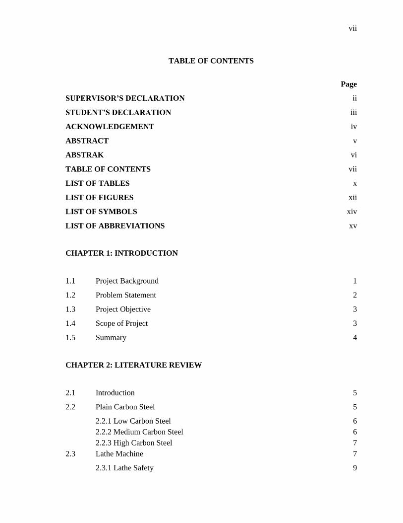
TABLE OF CONTENTS
Page
SUPERVISOR’S DECLARATION ii
STUDENT’S DECLARATION iii
ACKNOWLEDGEMENT iv
ABSTRACT v
ABSTRAK vi
TABLE OF CONTENTS vii
LIST OF TABLES x
LIST OF FIGURES xii
LIST OF SYMBOLS xiv
LIST OF ABBREVIATIONS xv
CHAPTER 1: INTRODUCTION
1.1 Project Background 1
1.2 Problem Statement 2
1.3 Project Objective 3
1.4 Scope of Project 3
1.5 Summary 4
CHAPTER 2: LITERATURE REVIEW
2.1 Introduction 5
2.2 Plain Carbon Steel 5
2.2.1 Low Carbon Steel 6
2.2.2 Medium Carbon Steel 6
2.2.3 High Carbon Steel 7
2.3 Lathe Machine 7
2.3.1 Lathe Safety 9
viii
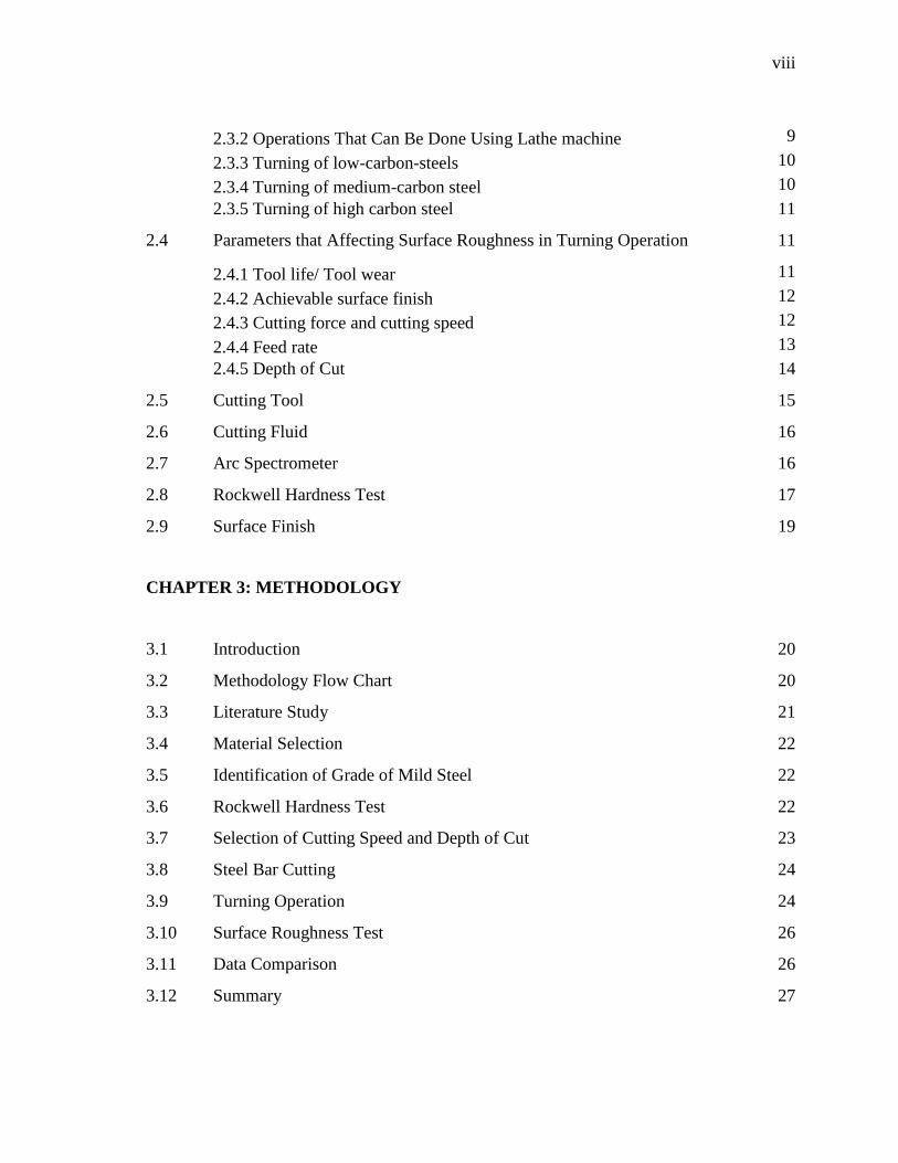
2.3.2 Operations That Can Be Done Using Lathe machine 9
2.3.3 Turning of low-carbon-steels 10
2.3.4 Turning of medium-carbon steel 10
2.3.5 Turning of high carbon steel 11
2.4 Parameters that Affecting Surface Roughness in Turning Operation 11
2.4.1 Tool life/ Tool wear 11
2.4.2 Achievable surface finish 12
2.4.3 Cutting force and cutting speed 12
2.4.4 Feed rate 13
2.4.5 Depth of Cut 14
2.5 Cutting Tool 15
2.6 Cutting Fluid 16
2.7 Arc Spectrometer 16
2.8 Rockwell Hardness Test 17
2.9 Surface Finish 19
CHAPTER 3: METHODOLOGY
3.1 Introduction 20
3.2 Methodology Flow Chart 20
3.3 Literature Study 21
3.4 Material Selection 22
3.5 Identification of Grade of Mild Steel 22
3.6 Rockwell Hardness Test 22
3.7 Selection of Cutting Speed and Depth of Cut 23
3.8 Steel Bar Cutting 24
3.9 Turning Operation 24
3.10 Surface Roughness Test 26
3.11 Data Comparison 26
3.12 Summary 27
ix
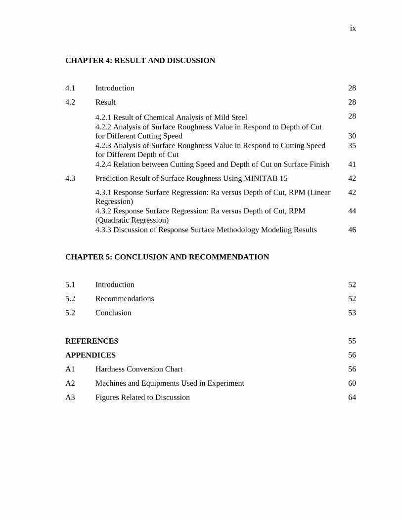
CHAPTER 4: RESULT AND DISCUSSION
4.1 Introduction 28
4.2 Result 28
4.2.1 Result of Chemical Analysis of Mild Steel 28
4.2.2 Analysis of Surface Roughness Value in Respond to Depth of Cut
for Different Cutting Speed 30
4.2.3 Analysis of Surface Roughness Value in Respond to Cutting Speed
for Different Depth of Cut
35
4.2.4 Relation between Cutting Speed and Depth of Cut on Surface Finish 41
4.3 Prediction Result of Surface Roughness Using MINITAB 15 42
4.3.1 Response Surface Regression: Ra versus Depth of Cut, RPM (Linear
Regression)
42
4.3.2 Response Surface Regression: Ra versus Depth of Cut, RPM
(Quadratic Regression)
44
4.3.3 Discussion of Response Surface Methodology Modeling Results 46
CHAPTER 5: CONCLUSION AND RECOMMENDATION
5.1 Introduction 52
5.2 Recommendations 52
5.2 Conclusion 53
REFERENCES 55
APPENDICES 56
A1 Hardness Conversion Chart 56
A2 Machines and Equipments Used in Experiment 60
A3 Figures Related to Discussion 64
x
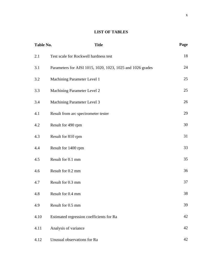
LIST OF TABLES
Table No. Title Page
2.1 Test scale for Rockwell hardness test 18
3.1 Parameters for AISI 1015, 1020, 1023, 1025 and 1026 grades 24
3.2 Machining Parameter Level 1 25
3.3 Machining Parameter Level 2 25
3.4 Machining Parameter Level 3 26
4.1 Result from arc spectrometer tester 29
4.2 Result for 490 rpm 30
4.3 Result for 810 rpm 31
4.4 Result for 1400 rpm 33
4.5 Result for 0.1 mm 35
4.6 Result for 0.2 mm 36
4.7 Result for 0.3 mm 37
4.8 Result for 0.4 mm 38
4.9 Result for 0.5 mm 39
4.10 Estimated regression coefficients for Ra 42
4.11 Analysis of variance 42
4.12 Unusual observations for Ra 42
xi
4.13 Estimated linear regression equation 43
4.14 Predicted response for new design points using model for Ra 43
4.15 Estimated regression coefficients for Ra 44
4.16 Analysis of variance 44
4.17 Unusual observations for Ra 45
4.18 Estimated quadratic regression equation 45
4.19 Predicted response for new design points using model for Ra 45
4.20 Data set used for checking the accuracy of RS model 48
xii
LIST OF FIGURES
Figure No. Title Page
2.1 Turning mechanism 15
3.1 Methodology Flow Chart 21
3.2 Bandsaw 60
3.3 Grinder 60
3.4 Arc spectrometer 61
3.5 Specimens after undergone spark-spectrometer test 61
3.6 Rockwell hardness tester 62
3.7 Cutting machine 62
3.8 Conventional lathe machine 63
3.9 Surface roughness tester, Perthometer 63
4.1 Graph of average surface roughness vs. depth of cut for 490 rpm 31
4.2 Graph of average surface roughness vs. depth of cut for 810 rpm 32
4.3 Graph of average surface roughness vs. depth of cut for 1400 rpm 33
4.4 Graph of average surface roughness vs. depth of cut for different rpm 34
4.5 Graph of surface roughness vs. spindle speed for 0.1 mm depth of cut 35
4.6 Graph of surface roughness vs. spindle speed for 0.2 mm depth of cut 36
4.7 Graph of surface roughness vs. spindle speed for 0.3 mm depth of cut 37
xiii
4.8 Graph of surface roughness vs. spindle speed for 0.4 mm depth of cut 38
4.9 Graph of surface roughness vs. spindle speed for 0.5 mm depth of cut 39
4.10 Graph of surface roughness vs. spindle speed for different depth of cut 40
4.11 Linear normal plot 46
4.12 Linear contour plot 47
4.13 Quadratic normal plot 47
4.14 Quadratic contour plot 48
5.1 Steel bar after turned 64
5.2 Available spindle speed on lathe machine 64

xiv
LIST OF SYMBOLS
D1 Initial diameter
D2 Final diameter
f Feed rate
r Tool nose radius
Ra Surface roughness
T Cutting time
v Cutting speed

xv
LIST OF ABBREVIATIONS
Al Aluminum
ANOVA Analysis of Variance
As Arsenic
B Boron
BHN Brinell Hardness Number
Bi Bismuth
BUE Build Up Edge
C Carbon
Ca Calcium
Co Cobalt
Cr Chromium
Cu Copper
DOC Depth of Cut
DOE Design of Experiment
Fe Iron
Mn Manganese
Mo Molybdenum
Nb Niobium
Ni Nickel
P Phosphorus

xvi
Pb Lead
RSM Response Surface Method
S Sulphur
Sn Tin
Ti Titanium
V Vanadium
W Tungsten
Zr Zirconium
CHAPTER 1
INTRODUCTION
1.1 PROJECT BACKGROUND
Steel had a major influence on our lives. The cars we drive, the buildings we work
in, the homes in which we live and countless other facets in between. Steel is used in our
electricity-power-line towers, natural-gas pipelines, machine tools, military weapons and so
on. Steel has also earned a place in our homes in protecting our families, making our lives
convenient, its benefits are undoubtedly clear. The backbone of developed economies was
laid on the strength and inherent uses of steel.
Steel is by far the most important, multi-functional and most adaptable materials.
Compared to other materials of its type, it has low production costs. The energy required
for extracting iron from ore is about 25 % of what is needed for extracting aluminum. Steel
is environment friendly for it is recycle-able. 5.6 % of element iron is present in earth's
crust, representing a secure raw material base. Steel production is 20 times higher as
compared to production of all non-ferrous. Steel is widely used in manufacturing processes
to produce various products.
Metal cutting processes are industrial processes in which metal parts are shaped or
removal of unwanted material. It is one of the most important and widely used
manufacturing processes in engineering industries. In the study of metal cutting, the output
quality is rather important. A significant improvement in output quality may be obtained by
optimizing the cutting parameters. Optimization of parameters not only improves output
2
quality, but also ensures low cost manufacturing. Cutting parameters include feed rate,
cutting speed, depth of cut, cutting fluids and so on. In turning process, cutting parameters
play critical roles in the efficient use of machine tool.
Lathe machine is the oldest machine tool that is still the most common used
machine in the manufacturing industry to produce cylindrical parts. For instance, shaft, axis
and bearing, are crucial in machining motions. It is widely used in variety of manufacturing
industries including aerospace and automotive sectors, where quality of surface plays a
very important role in the performance of turning as good-quality turned surface is
significant in improving fatigue strength, corrosion resistance, and creep life. Surface
roughness also affects several functional attributes of parts, such as wearing, heat
transmission, ability of holding a lubricant, coating, or resisting fatigue. Nowadays,
roughness plays a significant role in determining and evaluating the surface quality of a
product as it affects the functional characteristic.
The product quality depends very much on surface roughness. Decrease of surface
roughness quality also leads to decrease of product quality. In field of manufacture,
especially in engineering, the surface finish quality can be a considerable importance that
can affects the functioning of a component, and possibly its cost. Surface roughness has
been receiving attention for many years in the machining industries. It is an important
design feature in many situations, such as parts subject to fatigue loads, precision fits,
fastener holes and so on. In terms of tolerances, surface roughness imposes one of the most
crucial constraints for the machines and cutting parameters selection in process planning.
1.2 PROBLEM STATEMENT
Surface finish is a quality that is specified by customer for machined parts. There
are many parameters that have effect on surface roughness, but most are difficult to
quantify adequately. In turning operation, there are many parameters such as cutting speed,
depth of cut and feed rate that have great impact on the surface finish. In order to maximize
3
the gains from turning operation, an accurate model of process must be constructed. In this
research, an attempt has been made to generate a surface roughness prediction.
Besides in manufacturing application, surface roughness is also important in
hygienic process applications. For example, system integrity and ease of
cleaning/sterilization is dependent upon valve design and internal surface finish. A smooth
surface finish reduces the risk of system contamination, and increases the speed of cleaning
and sterilization.
All these while, there are numbers of studies are done to investigate the general
effects of feed, cutting speed and depth of cut on the surface roughness. Thus, in this
research, turning operations will be carried out to generate the optimum surface finish by
using cutting speed and depth of cut as parameters. The material that will be used is mild
steel.
1.3 PROJECT OBJECTIVES
The objectives of this research are as following:
i. Identify the composition and grade of mild steel.
ii. Study the effect of cutting parameters on the surface quality of the machined
surfaces.
iii. Develop surface prediction technique which is termed response surface
methodology.
iv. Evaluate prediction ability of model.
1.4 SCOPE OF PROJECT
In this project, mild steel is used as specimen. The specification of the mild steel
will be identified using spectrometer. Turning operation is performed using lathe machine.
Turning operation will be done on mild steel based on 2 machining parameters. The 2
parameters that will be used are cutting speed and depth of cut (DOC). Feed rate in this

4
case is set as a constant throughout the whole experiments. The surface roughness of each
of the specimen will be studied and compared.
1.5 SUMMARY
Chapter 1 has been discussed briefly about project background, problem statement,
objective and scope of the project on the effects of cutting speed and depth of cut on the
surface roughness of mild steel using turning operation. This chapter is as a fundamental
for the project and act as a guidelines for project research completion.
CHAPTER 2
LITERATURE REVIEW
2.1 INTRODUCTION
From the early stage of the project, various literature studies have been done.
Research journal, reference books, printed or online conference article were the main
source in the project guides as they contain the current knowledge on particular research.
The reference sources emphasize on effect of cutting speed and depth of cut on the surface
roughness of mild steel using lathe machine for turning operation. Then, the effects of
cutting speed and depth of cut on mild steel will be justified using surface roughness value.
2.2 CARBON STEEL
Carbon steel is a metal alloy, a combination of two elements that are iron and
carbon, where other elements are present in quantities too small to affect the properties. It is
by far the most frequent used steel. The feasibility of using carbon steels depend on
whether or not their properties (tensile, yield, and fatigue strength; impact resistance, need
for heat treating, etc.) are suitable for parts to be used (Isakov, 2009). Carbon steels may be
further classified into 3 major groups: low carbon steel, medium carbon steel and high
carbon steel.
Standard wrought-steel compositions (for both carbon and alloy steels) are
designated by an AISI or SAE four-digit code, the last two digits of which indicate the
nominal carbon content. The carbon-steel grades are:
6
10xx: Plain carbon
11xx: Resulfurized
12xz: Resulfurized and rephosphorized
15xx: Nonresulfurized, Mn over 1.0 %
2.2.1 Low Carbon Steel
Low carbon steel, also known as mild steel, contains 0.05 % to 0.26 % of carbon
(e.g. AISI 1018, AISI 1020 steel). These steels are ductile and have properties similar to
iron. They cannot be modified by heat treatment. They are cheap, but engineering
applications are restricted to non-critical components and general paneling and fabrication
work. These steels cannot be effectively heat treated. Consequently, there are usually no
problems associated with heat affected zones in welding process. The surface properties
can be enhanced by carburizing and then heat treating the carbon-rich surface. High
ductility characteristic results in poor machinability.
2.2.2 Medium Carbon Steel
Medium carbon steel contains 0.29 % to 0.54 % of carbon (e.g. AISI 1040, AISI
1045 steel). These steels are highly susceptible to thermal treatments and work hardening.
They easily flame harden and can be treated and worked to yield high tensile strengths
provided that low ductility can be tolerated. The corrosion resistance of these steels is
similar to low carbon steel, although small additions of copper can lead to significant
improvements when weathering performance is important. Medium carbon steels which are
still cheap and command mass market. They are general purpose but can be specified for
use in stressed applications such as rails and rail products, couplings, crankshafts, axles,
bolts, rods, gears, forgings, tubes, plates and constructional steels.
7
2.2.3 High Carbon Steel
High carbon steel contains 0.55 % to 0.95 % carbon (e.g. AISI 1086, AISI 1090).
Cold working is not possible with any of these steels, as they fracture at very low
elongation. They are highly sensitive to thermal treatments. Machinability is good, although
their hardness requires machining in the normalized condition. Welding is not
recommended and these steels must not be subjected to impact loading. They are normally
used for components that require high hardness such as cutting tools and blades.
2.3 LATHE MACHINE
Lathes are generally considered as the oldest machine tools. Wood-working lathes
originally were developed during the period 1000-1001 B.C.. However metalworking lathes
with leadscrew were only built during late 1700s. The most common laths originally was
called an engine lathes, because it was powered with overhead pulleys and belts from
nearby engines on the factory floor. Today, these lathes are all equipped with individual
electric motors (Kalpakjian, 2006).
Lathe machine is considered as the backbone of machine shop, and a through
knowledge of it is essential for machinist. Lathe machine is a machine which work is held
so that it can be rotated about an axis while the cutting tool is traversed past the work from
one end to the other thereby forming it to the required shape (Steeds, 1964).
Common operations performed on a lathe are: facing, parallel turning, taper turning,
knurling, thread cutting, drilling, reaming, and boring (Krar, undated). The spindle is the
part of the lathe that rotates. Various workholding attachments such as three jaw chucks,
collets, and centers can be held in the spindle. The spindle is driven by an electric motor
through a system of belt drives and/or gear trains. Spindle speed is controlled by varying
the geometry of the drive train. The main function of lathe is to provide a means of rotating
a workpiece against a cutting tool, thereby removing metal. All lathes, regardless of size
and design are basically the same and serve 3 functions:
8
A support for the lathe accessories or the workpiece
A way of holding and revolving the workpiece
A means of holding and moving the cutting tool
Size of the engine lathe is determined by the max diameter of work which may be
revolved or swung over the bed, and the longest part that can be held between lathe centers.
Lathes found in training programs generally have swing of 9.0 to 13.0 in (230-330 mm) and
bed length from 20.0 to 60.0 in (500-1500 mm). Lathes used in industry may be much
larger, doubling in swing and capacity (Krar, undated).
Bed is a heavy rugged casting made to support the working parts of the lathe. On its
top section are major parts of lathe. Commonly, lathes are made with flame-hardened and
ground ways to reduce wear and to maintain accuracy.
Headstock is attached to the left side of the bed. The headstock spindle is a hollow
cylindrical shaft supported by bearing. It provides a drive from the motor to workholding
devices. Live center, sleeve, face plate or a chuck can be fitted to the spindle nose to hold
and drive the work. The live center has 60o point that provides a bearing surface for the
work to turn between centers. Most modern lathes are geared-head and the spindle is driven
by series of gears in the headstock. Through a series of levers, different gears can be
engaged to set various spindle speeds for different types of sizes of work (Krar, undated).
The types of speed-change levers or controls used on each lathe machine are varying,
depending on the manufacturers. The feed-reverse lever can be place in three positions.
One position provides forward direction; the center position is neutral while the other
position reverses the feed rod direction and leadscrew.
Tailstock is made up of two units. The top half can be adjusted on the base by two
adjusting screws for aligning the tailstock and headstock center for parallel turning. These
screws can also be used to offset the tailstock for taper turning between centers. Tailstock
can be lock at any position along the bed of lathe by clamping the lever or tighten the nut.