Embed Size (px)
Citation preview
Haiyang HeDepartment of Mechanical and
Industrial Engineering,
2039 Engineering Research Facility,
University of Illinois at Chicago,
842 W. Taylor Street,
Chicago, IL 60607
e-mail: [email protected]
Jie XuMem. ASME
Department of Mechanical and Industrial
Engineering,
2039 Engineering Research Facility,
University of Illinois at Chicago,
842 W. Taylor Street,
Chicago, IL 60607
e-mail: [email protected]
Xiaoming YuMem. ASME
College of Optics &Photonics,
University of Central Florida CREOL,
4304 Scorpius Street,
Orlando, FL 32816-2700
e-mail: [email protected]
Yayue Pan1
Mem. ASME
Department of Mechanical and
Industrial Engineering,
2039 Engineering Research Facility,
University of Illinois at Chicago,
842 W. Taylor Street,
Chicago, IL 60607
e-mail: [email protected]
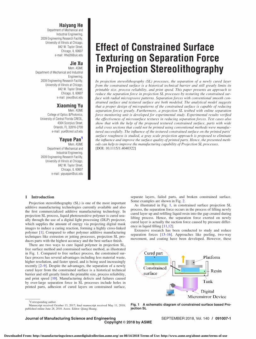
Effect of Constrained SurfaceTexturing on Separation Forcein Projection StereolithographyIn projection stereolithography (SL) processes, the separation of a newly cured layerfrom the constrained surface is a historical technical barrier and still greatly limits itsprintable size, process reliability, and print speed. This paper presents an approach toreduce the separation force in projection SL processes by texturing the constrained sur-face with radial microgroove patterns. Separation forces with conventional smooth con-strained surface and textured surface are both modeled. The analytical model suggeststhat a proper design of micropatterns of the constrained surface is capable of reducingseparation forces greatly. Furthermore, a projection SL testbed with online separationforce monitoring unit is developed for experimental study. Experimental results verifiedthe effectiveness of microsurface textures in reducing separation forces. Test cases alsoshow that with the help of the proposed textured constrained surface, parts with widesolid cross sections that could not be printed using conventional methods were manufac-tured successfully. The influence of the textured constrained surface on the printed parts’surface roughness is studied, a gray scale projection approach is proposed to eliminatethe influence and improve the surface quality of printed parts. Hence, the presented meth-ods can help to improve the manufacturing capability of Projection SL processes.[DOI: 10.1115/1.4040322]
1 Introduction
Projection stereolithography (SL) is one of the most importantadditive manufacturing technologies currently available and alsothe first commercialized additive manufacturing technology. Inprojection SL process, liquid photosensitive polymer is cured usu-ally through the use of a digital light processing (DLP) projector,which supplies the amount of energy via projecting digital maskimages to induce a curing reaction, forming a highly cross-linkedpolymer [1]. Compared to other polymer additive manufacturingtechniques like extrusion or jetting processes, projection SL pro-duces parts with the highest accuracy and the best surface finish.
There are two ways to cure liquid polymer in projection SL,free surface method and constrained surface method, as illustratedin Fig. 1. Compared to free surface process, the constrained sur-face process has several advantages including less material waste,higher resolution, and faster speed, and is being used increasinglyrecently [2–9]. Despite the advantages, the separation of a newlycured layer from the constrained surface is a historical technicalbarrier and still greatly limits the printable size, process reliability,and print speed [10]. Manufacturing defects and failures causedby over-large separation force in SL processes include holes inprinted parts, adhesion of cured layers on constrained surface,
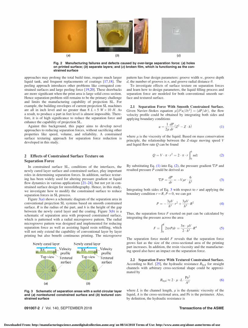
separate layers, failed parts, and broken constrained surface.Some examples are shown in Fig. 2.
As illustrated in Fig. 1, in constrained surface projection SLprocess, the separation force occurs in the process of lifting newlycured layer up and refilling liquid resin into the gap created duringlifting process. Hence, the separation force exerted on newlycured layer is actually the suction force caused by pressure differ-ence in liquid filling [11,12].
Extensive research has been conducted to study and reduceseparation forces [13–16]. Approaches like peeling, two-waymovement, and coating have been developed. However, these
Fig. 1 A schematic diagram of constrained surface based Pro-jection SL
1Corresponding author.Manuscript received October 13, 2017; final manuscript received May 11, 2018;
published online June 28, 2018. Assoc. Editor: Qiang Huang.
Journal of Manufacturing Science and Engineering SEPTEMBER 2018, Vol. 140 / 091007-1Copyright VC 2018 by ASME
Downloaded From: http://manufacturingscience.asmedigitalcollection.asme.org/ on 08/14/2018 Terms of Use: http://www.asme.org/about-asme/terms-of-use
approaches may prolong the total build time, require much largerliquid tank, and frequent replacements of coatings [17,18]. Thepeeling approach introduces other problems like corrugated con-strained surfaces and large peeling force [19,20]. These drawbacksare more significant when the print area is large solid cross section.Hence separation problem still remains to be the primary challengeand limits the manufacturing capability of projection SL. Forexample, the building envelopes of current projection SL machinesare all in inch level and no greater than 8 L� 5 W� 10 H. Asa result, to produce a part in feet level is almost impossible. There-fore, it is of high significance to reduce the separation force andenhance the capability of projection SL.
Against this background, this paper aims to develop novelapproaches to reducing separation forces, without sacrificing otherproperties like speed, volume, and reliability. A constrainedsurface texturing approach for separation force reduction isdeveloped in this study.
2 Effects of Constrained Surface Texture on
Separation Force
In constrained surface SL, conditions of the interfaces, thenewly cured layer surface and constrained surface, play importantroles in determining separation forces. In addition, surface textur-ing has been widely used for altering pressure gradient or liquidflow dynamics in various applications [21–24], but not yet in con-strained surface design for stereolithography. Hence, in this study,we investigate how to modify the constrained surface to reduceseparation forces in SL process.
Figure 3(a) shows a schematic diagram of the separation area inconventional projection SL systems based on smooth constrainedsurface. R is the radius of the part, and h is the height of the gapbetween the newly cured layer and the coating. Figure 3(b) is aschematic of separation area with proposed constrained surface,which is patterned with a radial microgroove pattern. The radialmicrogroove pattern was designed and implemented for reducingseparation force as well as assisting liquid resin refilling, whichwill not only extend the capability of conventional layer by layerprinting but also benefit continuous printing. The microgroove
pattern has four design parameters: groove width w, groove depthd, the number of grooves is n, and groove radial distance h.
To investigate effects of surface texture on separation forcesand learn how to design parameters, the liquid filling process andseparation force are modeled for both conventional smooth sur-face and textured surface.
2.1 Separation Force With Smooth Constrained Surface.Given Navier–Stokes equation l @2u=@z2
� �¼ dP=drð Þ; the flow
velocity profile could be obtained by integrating both sides andapplying boundary conditions
u ¼ 1
2ldP
drZ2 � Z � hð Þ (1)
where l is the viscosity of the liquid. Based on mass conservationprinciple, the relationship between the Z-stage moving speed Vand liquid flow rate Q can be found
Q ¼ V � p � r2 ¼ 2 � p � rðh
0
udz (2)
By substituting Eq. (1) into Eq. (2), the pressure gradient rP andresulted pressure P could be derived as
rP ¼ dP
dr¼ �Vlr � 6
h3(3)
Integrating both sides of Eq: 3 with respect to r and applying theboundary condition r¼R, P¼ 0, we can get
P ¼ � 3lV
h3�r2 þ 3lV
h3�R2 (4)
Thus, the separation force F exerted on part can be calculated byintegrating the pressure across the area
F ¼ðR
0
2prPdr ¼ 3p � lV
2 � h3�R4 (5)
The separation force model F reveals that the separation forcegrows fast as the size of the cross-sectional area of the printingpart increases. In addition, the resin viscosity and the manufactur-ing speed also have an impact on the separation force.
2.2 Separation Force With Textured Constrained Surface.According to Ref. [25], the hydraulic resistance Rhyd for straightchannels with arbitrary cross-sectional shape could be approxi-mated by
Rhyd � 2 � l � L � Pe2
A3(6)
where L is the channel length, l is the dynamic viscosity of theliquid, A is the cross-sectional area, and Pe is the perimeter. Also,by definition, the hydraulic resistance is
Fig. 2 Manufacturing failures and defects caused by over-large separation force: (a) holeson printed surface; (b) separate layers; and (c) broken film, which is functioning as the con-strained surface
Fig. 3 Schematic of separation areas with a solid circular layerand (a) nontextured constrained surface and (b) textured con-strained surface
091007-2 / Vol. 140, SEPTEMBER 2018 Transactions of the ASME
Downloaded From: http://manufacturingscience.asmedigitalcollection.asme.org/ on 08/14/2018 Terms of Use: http://www.asme.org/about-asme/terms-of-use
Rhyd DPð Þ � DP
Q DPð Þ (7)
where DP is a certain pressure drop and Q is the flow rate.From Eqs. (6) and (7), we can obtain DP=L ¼ 2 � l � Q DPð Þ
� Pe2=A3� �
. Thus, the pressure gradient for channel length dr alongthe radius is
rP ¼ dP
dr¼ Q � 2l � Pe2
A3(8)
For situation with microtextures
Pe ¼ 2 � 2p � r þ 2 � n � d
cosða=2Þ �w
2
� �(9)
A ¼ 2p � r � hþ 0:5n � w � d (10)
Q ¼ V � p � r2 (11)
where V is the separation speed, n is the number of grooves, wand d are the width and depth of the grooves, and h denotes theheight of the gap.
By substituting Eqs. (9)–(11) into Eq. (8), we can obtain
rP ¼ dP
dr¼ V � pr2 � 2l �
2 � 2p � r þ 2 � n � d
cosða=2Þ �w
2
� �� �2
2p � r � hþ 0:5n � w � dð Þ3
(12)
By taking integral of the pressure P on each unit circle, the separa-tion force could be calculated. To investigate the effects of micro-grooves on separation force reduction, pressure gradient iscalculated for textured surface using Eq. (12), and then comparedwith pressure gradient for smooth surface in Eq. (3). It was foundthat textured surface will reduce pressure gradient by �60% com-pared with conventional smooth surface when other conditions arerestricted the same and hence smaller separation force than thoseof smooth polydimethylsiloxane (PDMS).
To achieve the smallest separation force, the pressure P shouldbe the lowest. Based on Eq: 12 and its derivative with respect to r,it could be found that pressure P is a convex function of r. There-fore, when r is in the domain of (0, R], P is the lowest when thepressure gradient rP ¼ dP=drð Þ is the smallest. It can also beseen that rP is a convex function of w and d. Thus, when otherconditions are fixed, to achieve the smallest pressure gradient, tak-ing the partial derivative of the pressure gradient with respect to win Eq. (12), we can get
@rP
@w¼ 2lVpr2
�2n 4pr þ 2nd
cosða=2Þ � nw
� �2prhþ 0:5ndwð Þ � 1:5nd 4pr þ 2nd
cosða=2Þ � nw
� �2" #
2prhþ nwdð Þ4(13)
Since w, d, n and h are all larger than zero and 4pr � nw, above equation cannot be zero.Similarly, take the partial derivative of the pressure gradient with respect to d in Eq. (12),
@rP
@d¼ 2lVpr2
4n
cosða=2Þ 4pr þ 2nd
cosða=2Þ � nw
� �2prhþ 0:5nwdð Þ � 1:5nw 4pr þ 2nd
cosða=2Þ � nw
� �2
2prhþ nwdð Þ4(14)
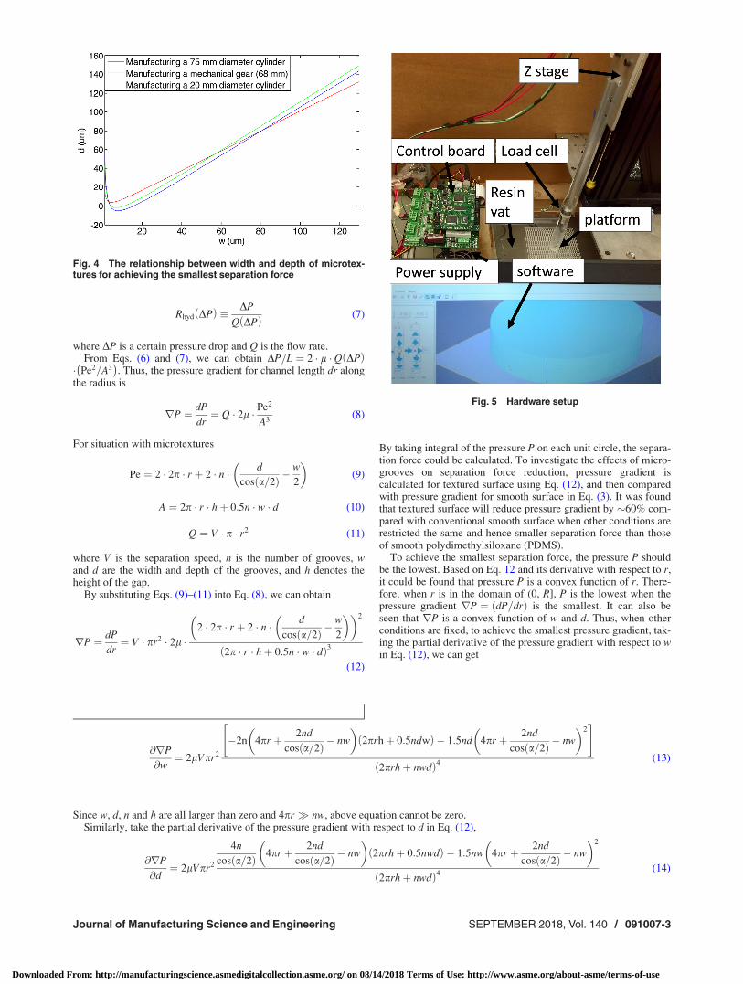
Fig. 4 The relationship between width and depth of microtex-tures for achieving the smallest separation force
Fig. 5 Hardware setup
Journal of Manufacturing Science and Engineering SEPTEMBER 2018, Vol. 140 / 091007-3
Downloaded From: http://manufacturingscience.asmedigitalcollection.asme.org/ on 08/14/2018 Terms of Use: http://www.asme.org/about-asme/terms-of-use
Set @rP=@d ¼ 0
d ¼ 16prhþ 3nw2cosða=2Þ � 12prwcosða=2Þ2nw
(15)
Therefore, the microtexture height and width, d and w, should bedesigned based on the relationship described in Eq. (15) forachieving the smallest separation force.
Based on the study in Ref. [26–30], the oxygen inhibition layerthickness above a PDMS film is �2 lm. Thus, when h is fixed at2 lm, the relationship between the width and depth of the micro-textures is shown in Fig. 4. The aforementioned relationship canbe used as a guide when designing the parameters of the textureson PDMS.
3 Textured Constrained Surface Based Projection
Stereolithography Experimental Setup
As shown in Fig. 5, a constrained surface based projection SLtestbed was built. The setup consists of an imaging unit, a resinvat, a linear actuator that elevates the build platform, a controlboard, and a load cell that measures the separation force. A loadcell from FUTEK (Irvine, CA) was mounted directly on the plat-form, so real-time force can be measured and recorded. An off-the-shelf DLP projector was used as the imagining unit. The opti-cal lenses of the projector were modified to reduce the projectiondistance. The light source was a 405 nm UV projector, which gavea focused image size of 128.97 mm� 96.44 mm and a resolutionof 1920� 1080. The DLP chip used was DLP6500FLQ fromTexas Instruments (Dallas, TX). It has a high-resolution arraywith over 2 million micromirrors. The micromirror pitch is7.56 lm. Various projection settings, including focus, key stonerectification, brightness, and contrast were adjusted to achieve asharp projection image on the projection plane. The resin vat wasmade with Acrylic. PDMS film was coated on the bottom of theresin vat by mixing the base polymer with curing agent with a 10to 1 weight ratio and microtextures were generated on the coatedPDMS film directly using the laser micromachining approach dis-cussed in Sec. 4.1. A precision position stage from Velmex wasused as the linear actuator that drives the platform along Z axis. Asix-axis motion control board from DYNOMOTION was imple-mented to control the Z-stage motion, light projection and to syn-chronize the motion and projection. A process control testbed wasdeveloped using Cþþ language. It integrated the geometry slic-ing, image projection, and motion controlling. In addition, anonline force monitoring testbed was developed in MATLAB. It readsand processes data from the load cell, and saves the separationforce in real time.
Conventional projection SL systems are usually based onsmooth PDMS films or smooth TEFLON films. In this study,PDMS films were prepared and coated on bottom surfaces of theresin vat. To explore the potential of textured constrained surfacein reducing separation forces, both conventional smooth PDMSfilms, and PDMS films with designed surface textures were tested.
For comparison, a commercial DLP 3D printer from Envision-TEC (Dearborn, MI) was also tested in the experiment. Asdescribed in the specs of the printer, the light source of this
commercial 3D printer is a UV light projector, which producesprojection image with a resolution of 1024� 768 and a full imagesize of 100.26 mm� 75.25 mm. A layer thickness of 50 lm wasused in all tests.
4 Experimental Results and Discussions
4.1 Polydimethylsiloxane Texturing and Force Measure-ments. Figure 3(b) is an illustration of the resin replenishmentwith a textured surface, where the constrained surface is patternedwith radially symmetric microgrooves. Those microgrooves willhelp increase the flow pathway cross section, hence the resin flowrate. Micropatterns with different parameter settings, i.e., widthand depth of the microgrooves, number of grooves, have been pre-pared on 1 mm thick PDMS substrates.
To generate microgrooves on PDMS, a conventional 1 mmsmooth PDMS film was first coated on the bottom of the resin vatby mixing the base polymer with curing agent with a 10 to 1weight ratio. After the PDMS coating was ready, designed micro-patterns were sent to a laser machine. By adjusting the laserparameters such as scanning speed and power, various geometriesof microgrooves could be fabricated on the PDMS coating.
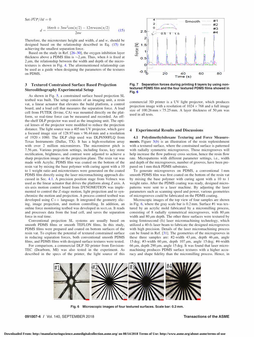
Microscopic images of the top view of four samples are shownin Fig. 6, where the gray scale bar is 0.2 mm. Surface #1 was tex-tured by an acrylic mold fabricated by a micromilling process,consisting of 8 radially symmetrical microgrooves, with 80 lmwidth and 80 lm depth. The other three surfaces were textured byusing femtosecond (fs) laser micromachining technology, whichutilized a 40-fs laser beam to fabricate the designed microgrooveswith high precision. Details of the laser micromachining processcan be found in Ref. [31]. The geometries of the microgrooves inthese three samples are: #2-width 43 lm, depth 46 lm, angle15 deg; #3-width 60 lm, depth 107 lm, angle 15 deg; #4-width66 lm, depth 290 lm, angle 15 deg. It was found that laser micro-machining produces PDMS surface textures with a higher accu-racy and shape fidelity than the micromilling process. Hence, in
Fig. 6 Microscopic images of four textured surfaces. Scale bar: 0.2 mm.
Fig. 7 Separation forces during printing 8 layers by using non-textured PDMS film and the four textured PDMS films showed inFig. 6
091007-4 / Vol. 140, SEPTEMBER 2018 Transactions of the ASME
Downloaded From: http://manufacturingscience.asmedigitalcollection.asme.org/ on 08/14/2018 Terms of Use: http://www.asme.org/about-asme/terms-of-use
this paper, the laser micromachining technique was used forPDMS surface texturing in all following experiments.
Experiments were carried out to test the effectiveness of micro-textures on separation force reduction. A solid cylinder with aradius of 10 mm has been built with the conventional projectionSL based on smooth constrained surface, and also with the pro-posed projection SL based on the textured surface (#2-width43 lm, depth 46 lm) as shown in Fig. 6. In all experiments, avelocity of Z elevator of 1.56 mm/s an acceleration of Z elevatorof 1.25 mm2/s, and a layer thickness of 203.2 lm are used. In addi-tion, the same resin MakerJuice Gþ with a viscosity of 90 cP isused in all tests.
Forces during printing in the developed SL testbed, with thetwo types of constrained surfaces, conventional smooth PDMSand textured PDMS surfaces, are measured. Figure 7 plots forcesin the process of printing eight successive layers by using smoothsurface and the four textured surface samples in Fig. 6. Comparedto the conventional smooth PDMS surface, separation forces inthe printing process are reduced by �60% by using texturedsurfaces.
Note that the PDMS surface also deforms in the separationprocesses. Hence, the peak of separation force does not occur
exactly in the initial moment of part elevation, and the actual sep-aration velocity V is smaller than the Z-stage velocity due to thedeformation of PDMS surface. The experimental results verifiedthat the separation force could be reduced greatly by modifyingthe constrained surface with radial microgroove textures.
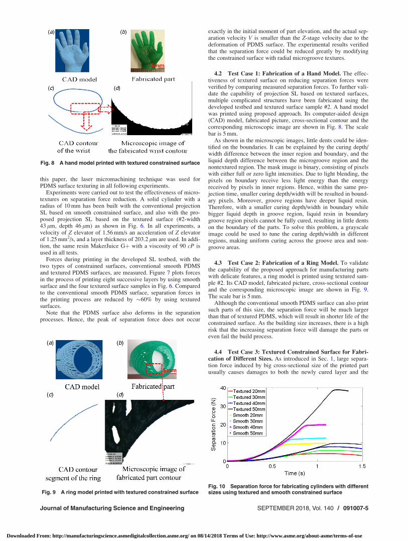
4.2 Test Case 1: Fabrication of a Hand Model. The effec-tiveness of textured surface on reducing separation forces wereverified by comparing measured separation forces. To further vali-date the capability of projection SL based on textured surfaces,multiple complicated structures have been fabricated using thedeveloped testbed and textured surface sample #2. A hand modelwas printed using proposed approach. Its computer-aided design(CAD) model, fabricated picture, cross-sectional contour and thecorresponding microscopic image are shown in Fig. 8. The scalebar is 5 mm.
As shown in the microscopic images, little dents could be iden-tified on the boundaries. It can be explained by the curing depth/width difference between the inner region and boundary, and theliquid depth difference between the microgroove region and thenontextured region. The mask image is binary, consisting of pixelswith either full or zero light intensities. Due to light blending, thepixels on boundary receive less light energy than the energyreceived by pixels in inner regions. Hence, within the same pro-jection time, smaller curing depth/width will be resulted in bound-ary pixels. Moreover, groove regions have deeper liquid resin.Therefore, with a smaller curing depth/width in boundary whilebigger liquid depth in groove region, liquid resin in boundarygroove region pixels cannot be fully cured, resulting in little dentson the boundary of the parts. To solve this problem, a grayscaleimage could be used to tune the curing depth/width in differentregions, making uniform curing across the groove area and non-groove areas.
4.3 Test Case 2: Fabrication of a Ring Model. To validatethe capability of the proposed approach for manufacturing partswith delicate features, a ring model is printed using textured sam-ple #2. Its CAD model, fabricated picture, cross-sectional contourand the corresponding microscopic image are shown in Fig. 9.The scale bar is 5 mm.
Although the conventional smooth PDMS surface can also printsuch parts of this size, the separation force will be much largerthan that of textured PDMS, which will result in shorter life of theconstrained surface. As the building size increases, there is a highrisk that the increasing separation force will damage the parts oreven fail the build process.
4.4 Test Case 3: Textured Constrained Surface for Fabri-cation of Different Sizes. As introduced in Sec. 1, large separa-tion force induced by big cross-sectional size of the printed partusually causes damages to both the newly cured layer and the
Fig. 8 A hand model printed with textured constrained surface
Fig. 9 A ring model printed with textured constrained surfaceFig. 10 Separation force for fabricating cylinders with differentsizes using textured and smooth constrained surface
Journal of Manufacturing Science and Engineering SEPTEMBER 2018, Vol. 140 / 091007-5
Downloaded From: http://manufacturingscience.asmedigitalcollection.asme.org/ on 08/14/2018 Terms of Use: http://www.asme.org/about-asme/terms-of-use
constrained surface. It is also indicated by the theoretical modelsthat the separation force would increase as the printing cross-sectional size increases. To test the effectiveness of the proposedtextured constrained surface, cylinders with different diameterswere printed with both conventional constrained surface and theproposed textured constrained surface. The width and depth ofmicrogrooves on the textured constrained surface were designedaccording to the theoretical model in Eq. (15) and manufacturedto be 105 lm and 119 lm, respectively, the number of grooveswas 24 (intergroove angle 15 deg). The materials used was Gþfrom MakerJuice Labs and the diameters of the cylinders were20 mm, 30 mm, 40 mm, and 50 mm. Separation forces for thosedifferent fabrication sizes were recorded and plotted in Fig. 10.For clear demonstration, only a half cycle of the separation forcewas plotted for each test case.
It can be seen from Fig. 10 that the separation force reached itspeak earlier when the printing cross-sectional size is smaller. It isbecause that the separation time is shorter when the printingcross-sectional size is smaller. In addition, it can be seen fromFig. 10 that the separation force increased dramatically as thecross-sectional size of the part increased, when the conventionalsmooth constrained surface is used. The peak separation forcereached �40 N during the process of printing a 50 mm diametercylinder. However, when a textured constrained surface was used,the separation force grew slightly with the fabrication size. It veri-fied the effectiveness of the proposed textured constrained surfacein reducing the separation force and fabricating parts with differ-ent sizes.
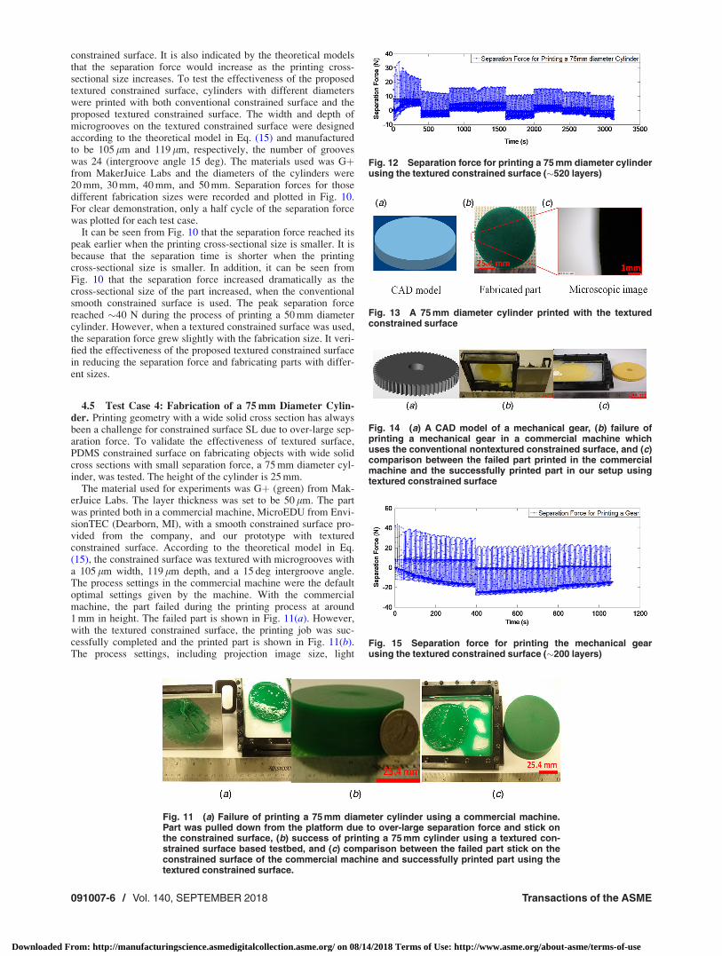
4.5 Test Case 4: Fabrication of a 75 mm Diameter Cylin-der. Printing geometry with a wide solid cross section has alwaysbeen a challenge for constrained surface SL due to over-large sep-aration force. To validate the effectiveness of textured surface,PDMS constrained surface on fabricating objects with wide solidcross sections with small separation force, a 75 mm diameter cyl-inder, was tested. The height of the cylinder is 25 mm.
The material used for experiments was Gþ (green) from Mak-erJuice Labs. The layer thickness was set to be 50 lm. The partwas printed both in a commercial machine, MicroEDU from Envi-sionTEC (Dearborn, MI), with a smooth constrained surface pro-vided from the company, and our prototype with texturedconstrained surface. According to the theoretical model in Eq.(15), the constrained surface was textured with microgrooves witha 105 lm width, 119 lm depth, and a 15 deg intergroove angle.The process settings in the commercial machine were the defaultoptimal settings given by the machine. With the commercialmachine, the part failed during the printing process at around1 mm in height. The failed part is shown in Fig. 11(a). However,with the textured constrained surface, the printing job was suc-cessfully completed and the printed part is shown in Fig. 11(b).The process settings, including projection image size, light
Fig. 11 (a) Failure of printing a 75 mm diameter cylinder using a commercial machine.Part was pulled down from the platform due to over-large separation force and stick onthe constrained surface, (b) success of printing a 75 mm cylinder using a textured con-strained surface based testbed, and (c) comparison between the failed part stick on theconstrained surface of the commercial machine and successfully printed part using thetextured constrained surface.
Fig. 12 Separation force for printing a 75 mm diameter cylinderusing the textured constrained surface (�520 layers)
Fig. 13 A 75 mm diameter cylinder printed with the texturedconstrained surface
Fig. 14 (a) A CAD model of a mechanical gear, (b) failure ofprinting a mechanical gear in a commercial machine whichuses the conventional nontextured constrained surface, and (c)comparison between the failed part printed in the commercialmachine and the successfully printed part in our setup usingtextured constrained surface
Fig. 15 Separation force for printing the mechanical gearusing the textured constrained surface (�200 layers)
091007-6 / Vol. 140, SEPTEMBER 2018 Transactions of the ASME
Downloaded From: http://manufacturingscience.asmedigitalcollection.asme.org/ on 08/14/2018 Terms of Use: http://www.asme.org/about-asme/terms-of-use
intensity, separation speed, and environmental conditions, are allthe same as those in the commercial machine. The comparisonbetween the failure part and our successful part is given inFig. 11(c).
The separation force for building the part with textured surfacewas recorded and is plotted in Fig. 12. The average separationforce is �18 N for each layer. Besides, there is no significantincrease of separation force over the manufacturing process,which is often seen in conventional constrained surface SL proc-esses [32,33]. The CAD model, fabricated picture, and the corre-sponding microscopic image are shown in Fig. 13.
4.6 Test Case 5: Fabrication of a Gear. To further demon-strate the capability and versatility of textured constrained surface,a common mechanical gear (�68 mm diameter, 10 mm in height)was printed. The material used was SL600M, produced by Envi-sionTEC. The part was printed using both a commercial machinewith conventional constrained surface and our setup with texturedsurface. The microgroove width and depth of the textured surfacewere designed according to the theoretical model in Eq. (15), and
manufactured to be 100 lm and 105 lm, respectively, with anintergroove angle of 15 deg. After printing a few layers in thecommercial machine, the part was pulled down from the platformby the large separation force and adhered to the constrained sur-face. Debris could be observed on the metal platform and the con-strained surface, as shown in Fig. 14(b).
However, with the textured surface, the gear can be success-fully printed. The comparison between these two parts are givenin Fig. 14(c) (scale bar: 25.4 mm). The separation force for manu-facturing this gear with textured was recorded during the wholeprocess, as plotted in Fig. 15.
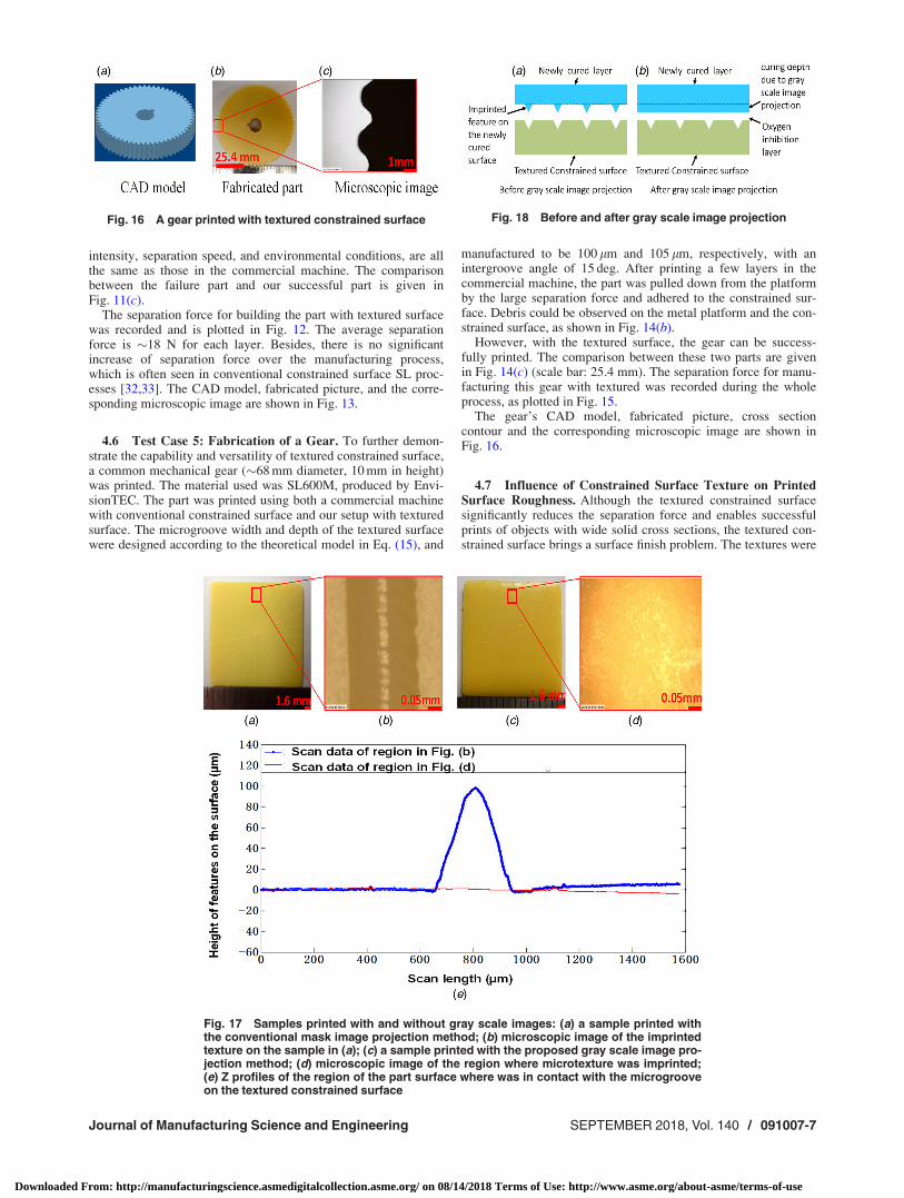
The gear’s CAD model, fabricated picture, cross sectioncontour and the corresponding microscopic image are shown inFig. 16.
4.7 Influence of Constrained Surface Texture on PrintedSurface Roughness. Although the textured constrained surfacesignificantly reduces the separation force and enables successfulprints of objects with wide solid cross sections, the textured con-strained surface brings a surface finish problem. The textures were
Fig. 16 A gear printed with textured constrained surface
Fig. 17 Samples printed with and without gray scale images: (a) a sample printed withthe conventional mask image projection method; (b) microscopic image of the imprintedtexture on the sample in (a); (c) a sample printed with the proposed gray scale image pro-jection method; (d) microscopic image of the region where microtexture was imprinted;(e) Z profiles of the region of the part surface where was in contact with the microgrooveon the textured constrained surface
Fig. 18 Before and after gray scale image projection
Journal of Manufacturing Science and Engineering SEPTEMBER 2018, Vol. 140 / 091007-7
Downloaded From: http://manufacturingscience.asmedigitalcollection.asme.org/ on 08/14/2018 Terms of Use: http://www.asme.org/about-asme/terms-of-use
imprinted on the part surface and could be observed. To betterunderstand the effects of textured constrained surface on surfacefinish of printed parts, this section characterizes the part surfacefinish and investigate approaches to eliminate the imprintedtextures.
Eight samples were manufactured using the textured PDMSconstrained surface and two different resins, MakerJuice andSL600. Figure 17(a) shows a sample and Fig. 17(b) shows amicroscopic image of the region that was printed by the micro-groove region of the PDMS film. As shown in Fig. 17(b), the resinin the radial microsurface texture of the constrained surface wascured and printed on the surface of the square part, forming ridgeshaped patterns extruding out on the surface of the printed part. AKLA-Tencor P7 stylus contact profilometer was used to character-ize the imprinted textures. The profiler physically moves a probealong the surface to acquire the surface height. When the probemoved from the middle point of the left edge of the region indi-cated in Fig. 17(b) to the middle point of the right edge of Fig.17(b), the corresponding profile is plotted as the blue curve in Fig.17(e). It can be seen that the height of the printed ridge is�100 lm, which is very close to the depth of the microgroove onthe PDMS surface.
To address this texture printing problem, a gray scale projectionmethod was investigated. After curing a layer, a sliced image withgray scale values (R: 110, G: 110, B: 110) of that layer was pro-jected [3,5]. By adjusting the gray scale values of pixels in animage, the light intensity distribution could be manipulated andthus the curing depth and width. Thus, by using a stronger lightintensity in the nontextured regions and weaker intensity in thegrooved regions, a bigger oxygen inhibition layer thickness willbe produced in the grooved region than the nontextured region,leading to a smooth newly cured layer with uniform thickness, asillustrated in the schematic of Fig. 18.
To test the feasibility of this method, the same square samplewas printed using this gray scale image method. Picture andmicroscopic image of the sample printed using the gray scaleimage method are shown in Figs. 17(c) and 17(d). The profile ofthe same region as in Fig. 17(b) is plotted as the red curve in Fig.17(e). It can be seen from Figs. 17(d) and 17(e) that with the grayscale image method, the imprinted texture feature could beavoided. It showed that undesired effects of the microgroove inthe PDMS constrained surface on the surface finish of printedparts could be eliminated by carefully controlling the light inten-sity distribution. Additionally, the surface roughness of 75 mmdiameter cylinder, mechanical gear, and square samples fabricatedwith textured PDMS surface were measured, as listed in Table 1.It can be seen that the gray scale image method is a feasibleapproach to eliminating the imprinted texture and improving thesurface roughness of printed parts.
5 Conclusions
A novel constrained surface texturing method for separationforce reduction in projection stereolithography systems is devel-oped in this study. Analytical models indicate that by modifyingthe constrained surface with radial microgroove patterns, theseparation force during printing process could be reduced greatly.Several PDMS samples with microgroove patterns are preparedusing micromilling and femtosecond laser micromachining
technologies. Separation forces during the printing process usingtextured constrained surfaces are measured and compared with theforces during printing process using the conventional nontexturedconstrained surface. Multiple parts have been built successfullywith the developed projection SL process based on texturedPDMS constrained surfaces. Experimental results verified theeffectiveness of constrained surface texturing approach in reduc-ing separation forces and fabricating 3D objects. Furthermore, thisstudy demonstrated advantages of the proposed textured con-strained surface in projection SL on fabricating parts with largesolid cross section areas, which are very challenging or evenimpossible with current constrained surface projection SL tech-nology due to over-large separation forces.
Future work will be conducted to (1) investigate a homogene-ous surface texture design and further optimize it; (2) develop thegray scale image method for eliminating the texture imprintingproblem for printing complicated geometries with high surfacefinish; and (3) study the effect of the textured constrained surfaceon the interlayer bonding and the mechanical strength of theprinted parts.
Acknowledgment
The authors would like to also acknowledge the Nanotechnol-ogy Core Facility of the University of Illinois at Chicago campusfor training on and usage of the Bruker-Nano Model Contour GT-K Optical Profilometer.
Funding Data
This material is based upon work supported by the NationalScience Foundation (Grant No. 1563477).
Nomenclature
d ¼ microgroove depthDLP ¼ digital light processing
F ¼ separation forceL ¼ channel lengthN ¼ number of microgroovesP ¼ pressure across the separation areaQ ¼ liquid resin flow rate
R_hyd ¼ hydraulic resistanceSL ¼ stereolithography
V ¼ Z-stage moving speedw ¼ microgroove widtha ¼ angle of each microgroovel ¼ viscosity of the resinh ¼ microgroove radial distance
rp ¼ ¼ pressure gradient across the part
References[1] Gibson, I., Rosen, D., and Stucker, B., 2014, Additive Manufacturing Technolo-
gies: 3D Printing, Rapid Prototyping, and Direct Digital Manufacturing,Springer, New York.
[2] Zhou, C., Chen, Y., Yang, Z. G., and Khoshnevis, B., 2011, “Development ofMulti-Material Mask-Image-Projection-Based Stereolithography for the Fabri-cation of Digital Materials,” Annual Solid Freeform Fabrication Symposium,Austin, TX, pp. 65–80.
[3] Pan, Y., Zhao, X., Zhou, C., and Chen, Y., 2012, “Smooth Surface Fabricationin Mask Projection Based Stereolithography,” J. Manuf. Processes, 14(4),pp. 460–470.
[4] Zhou, C., Chen, Y., Yang, Z., and Khoshnevis, B., 2013, “Digital MaterialFabrication Using Mask-Image-Projection-Based Stereolithography,” RapidPrototyping J., 19(3), pp. 153–165.
[5] Zhou, C., and Chen, Y., 2012, “Additive Manufacturing Based on OptimizedMask Video Projection for Improved Accuracy and Resolution,” J. Manuf.Processes, 14(2), pp. 107–118.
[6] Deng, D., and Chen, Y., 2015, “Origami-Based Self-Folding Structure Designand Fabrication Using Projection Based Stereolithography,” ASME J. Mech.Des., 137(2), p. 021701.
[7] Pan, Y., Patil, A., Guo, P., and Zhou, C., 2017, “A Novel Projection BasedElectro-Stereolithography (PES) Process for Production of 3D Polymer-ParticleComposite Objects,” Rapid Prototyping J., 23(2), pp. 236–245.
Table 1 Roughness measurements of parts fabricated withtextured constrained surface
Models Ra (lm) Rq (lm) Rz (lm)
Square sample (before eliminating textures) 0.58167 0.39486 23.754Square sample (after eliminating textures) 0.25126 0.33688 2.22475 mm diameter cylinder 0.792 0.98444 24.055Mechanical gear 0.27684 0.35599 25.155
091007-8 / Vol. 140, SEPTEMBER 2018 Transactions of the ASME
Downloaded From: http://manufacturingscience.asmedigitalcollection.asme.org/ on 08/14/2018 Terms of Use: http://www.asme.org/about-asme/terms-of-use
[8] Pan, Y., and Dagli, C., 2017, “Dynamic Resolution Control in a LaserProjection-Based Stereolithography System,” Rapid Prototyping J., 23(1), pp.190–200.
[9] He, H., Pan, Y., Feinerman, A., and Xu, J., 2018, “Air-Diffusion-Channel Con-strained Surface Based Stereolithography for Three-Dimensional Printing of ObjectsWith Wide Solid Cross Sections,” ASME J. Manuf. Sci. Eng., 140(6), p. 061011.
[10] Ikuta, K., and Hirowatari, K., 1993, “Real Three Dimensional Micro Fabrica-tion Using Stereo Lithography and Metal Molding,” An Investigation of MicroStructures, Sensors, Actuators, Machines and Systems Micro Electro Mechani-cal Systems (MEMS’93), Fort Lauderdale, FL, Feb. 10, pp. 42–47.
[11] He, H., Pan, Y., Xu, J., Yu, X., and Botton, V., 2016, “Effect of Surface Textur-ing on Separation Force in Projection Stereolithography,” 11th InternationalConference on Micro Manufacturing (ICOMM), Irvine, CA, Mar. 29–31, p. 82.
[12] He, H., Pan, Y., Xu, J., and Yu, X., 2017, “Effect of Constrained Surface Tex-turing on Separation Force in Projection Stereolithography,” Solid FreeformFabrication Symposium, Austin, TX, pp. 1735–1749.
[13] Ye, H., Das, S., and Zhou, C., 2015, “Investigation of Separation Force forBottom-Up Stereolithography Process From Mechanics Perspective,” ASMEPaper No. DETC2015-47673.
[14] Liravi, F., Das, S., and Zhou, C., 2014, “Separation Force Analysis Based onCohesive Delamination Model for Bottom-Up Stereolithography Using FiniteElement Analysis,” 25th Annual International Solid Freeform FabricationSymposium, Austin, TX, Aug. 4–6, pp. 1432–1451.
[15] Huang, Y. M., and Jiang, C. P., 2005, “On-Line Force Monitoring of PlatformAscending Rapid Prototyping System,” J. Mater. Process. Technol., 159(2),pp. 257–264.
[16] Liravi, F., Das, S., and Zhou, C., 2015, “Separation Force Analysis and Predic-tion Based on Cohesive Element Model for Constrained-Surface Stereolithogra-phy Processes,” Comput. Aided Des., 69, pp. 134–142.
[17] Denken Corp., 1997, “SLP-4000 Solid Laser Diode Plotter,” Product Brochure,Denken Corporation, Niigata, Japan.
[18] Pan, Y., Zhou, C., and Chen, Y., 2012, “A Fast Mask Projection Stereolithogra-phy Process for Fabricating Digital Models in Minutes,” ASME J. Manuf. Sci.Eng., 134(5), p. 051011.
[19] Lambert, P. M., Campaigne, E. A., III, and Williams, C. B., 2013, “DesignConsiderations for Mask Projection Microstereolithography Systems,” SolidFreeform Fabrication Symposium, Austin, TX, Aug. 12–14, p. 111.
[20] John, H., and EnvisionTEC GmbH, 2007, “Apparatus and Method for the Non-Destructive Separation of Hardened Material Layers From a Flat ConstructionPlane,” EnvisionTEC Inc., Dearborn, MI, U.S. Patent No. 7,195,472.
[21] Srinivasan, S., Kleingartner, J. A., Gilbert, J. B., Cohen, R. E., Milne, A. J., andMcKinley, G. H., 2015, “Sustainable Drag Reduction in Turbulent Taylor-Couette Flows by Depositing Sprayable Superhydrophobic Surfaces,” Phys.Rev. Lett., 114(1), p. 014501.
[22] Xu, L., 2007, “Liquid Drop Splashing on Smooth, Rough, and TexturedSurfaces,” Phys. Rev. E, 75(5), p. 056316.
[23] Qu�er�e, D., Lafuma, A., and Bico, J., 2003, “Slippy and Sticky MicrotexturedSolids,” Nanotechnology, 14(10), pp. 1109–1112.
[24] Nicolaiewsky, E. M., and Fair, J. R., 1999, “Liquid Flow OverTextured Surfaces—Part 1: Contact Angles,” Ind. Eng. Chem. Res., 38(1), pp.284–291.
[25] Bruus, H., 2007, Theoretical Microfluidics, Oxford University Press, Oxford,UK.
[26] Tumbleston, J. R., Shirvanyants, D., Ermoshkin, N., Janusziewicz, R., Johnson,A. R., Kelly, D., Chen, K., Pinschmidt, R., Rolland, J. P., Ermoshkin, A., andSamulski, E. T., 2015, “Continuous Liquid Interface Production of 3D Objects,”Science, 347(6228), pp. 1349–1352.
[27] Dendukuri, D., Pregibon, D. C., Collins, J., Hatton, T. A., and Doyle, P. S.,2006, “Continuous-Flow Lithography for High-Throughput Microparticle Syn-thesis,” Nat. Mater., 5(5), pp. 365–369.
[28] Yagci, Y., Jockusch, S., and Turro, N. J., 2010, “Photoinitiated Polymerization:Advances, Challenges, and Opportunities,” Macromolecules, 43(15),pp. 6245–6260.
[29] Dendukuri, D., Panda, P., Haghgooie, R., Kim, J. M., Hatton, T. A., andDoyle, P. S., 2008, “Modeling of Oxygen-Inhibited Free Radical Photopo-lymerization in a PDMS Microfluidic Device,” Macromolecules, 41(22),pp. 8547–8556.
[30] Gonz�alez-M�eijome, J. M., Compa~n-Moreno, V., and Riande, E., 2008,“Determination of Oxygen Permeability in Soft Contact Lenses Using a Polaro-graphic Method: Estimation of Relevant Physiological Parameters,” Ind. Eng.Chem. Res., 47(10), pp. 3619–3629.
[31] Bian, Q., Yu, X., Zhao, B., Chang, Z., and Lei, S., 2013, “Femtosecond LaserAblation of Indium Tin-Oxide Narrow Grooves for Thin Film Solar Cells,”Opt. Laser Technol., 45, pp. 395–401.
[32] Pan, Y., He, H., Xu, J., and Feinerman, A., 2017, “Study of Separation Force inConstrained Surface Projection Stereolithography,” Rapid Prototyping J., 23(2),pp. 353–361.
[33] Zguris, Z., 2016, “How Mechanical Properties of Stereolithography 3D PrintsAre Affected by UV Curing,” Formlabs Inc., Somerville, MA, accessed Mar. 7,2017, https://formlabs.com
Journal of Manufacturing Science and Engineering SEPTEMBER 2018, Vol. 140 / 091007-9
Downloaded From: http://manufacturingscience.asmedigitalcollection.asme.org/ on 08/14/2018 Terms of Use: http://www.asme.org/about-asme/terms-of-use


![Continuous Wave Diode Laser Surface Texturing of ... · laser surface irradiation with strong texturing influence on account of the induced high thermal gradients [13]- [16]. The](https://img.pdfslide.us/doc/110x75/5ffc0b7108bd6722b42291db/continuous-wave-diode-laser-surface-texturing-of-laser-surface-irradiation-with.jpg)