Embed Size (px)
Citation preview
energyequipsys/ Vol 3/No2/Dec 2015/ 83-95
Energy Equipment and Systems
http://energyequipsys.ut.ac.ir www.energyeuquipsys.com
Effect of conjugate heat transfer in designing thermoelectric beverage cooler
Authors
Akram Gholami Pareha
Mojtaba Maktabifardb
Zahra Ojaghi Seyed Saranc
Farschad Torabic*
a Engineering Department, University of
Florida, Gainesville, Florida, USA b
Renewable Energies Department, Institut
Teknologi Bandung, Bandung, Indonesia c
Mechanical Engineering Faculty, K. N.
Toosi University of Technology, Tehran, Iran
ABSTRACT
Peltier technology opens new opportunities for special applications. In the current project, this technology was applied to design and fabricate a portable thermoelectric beverage cooler and thermoelectric cup. The simulation and results of the experiment showed that the common beverage cooler is not a suitable design for ignoring the effect of natural convection in cooling. In our thermoelectric cup, the drawbacks of previous design were eliminated. The advantages of the present design over the former design are the heat sink's temperature reduction from 60°C to about 31°C, and the cooling process enhancement, such that the water was cooled down to about 7°C.
Article history:
Received : 12 August 2015 Accepted : 13 October 2015
Keywords: Natural Convection, Peltier Effect, Thermoelectric, Thermoelectric Beverage Cooler, Thermoelectric
Cup.
1. Introduction
Thermoelectric devices can be used for cooling purposes and are known as thermoelectric coolers (TECs) or Peltier coolers. These devices are solid state and are made in small scales which make them interesting for producing cold drinking water [1-5]. In most of the present water or beverage coolers, a common cooling system like standard compression, absorptive or adsorptive cycles are incorporated [6].
The reason for making a portable cooler is that all other products in the market are heavy, expensive, and use electricity from the wall plugs. Also, regular refrigerators take a *Corresponding author: Farschad Torabi Address: Mechanical Engineering Faculty, K. N. Toosi University of Technology, Tehran, Iran E-mail address: [email protected]
long time to properly cool a beverage can (more than 160 min) [7]. In contrast, TECs are small, cheap (for small applications), and require direct current (DC) electricity with low voltage which can be obtained from any power source like car lighter plug or USB ports of a computer. In addition, Peltier elements are very reliable and durable due to the absence of moving parts which are subject to wear. They are maintenance-free and easy to replace in case of failure (if any) [1, 2, 8, 9, 10]. Therefore, a TEC beverage cooler can inherit all the above characteristics which may be practical for the customers [11, 12]. The main user group targeted with this product is people interested in outdoor activities. This product can also be useful for people working in places without refrigerator.
Moreover, the Peltier effect is reversible,

84 Akram Gholami Pareh et al./energyequipsys / Vol 3/No2/Dec 2015
that is, one can change the direction of electrical current to get a warmer with the same device [13]. In other words, with a single proper design and by using an electrical switch, we can have a beverage cooler and warmer at the same time.
As every other systems, TEC can also have disadvantages. The main drawback of such systems is their intrinsic low efficiency [10]. Normally, TEC offers an efficiency around 10 to 15% of the ideal Carnot cycle refrigerator. This should be compared with 40 to 60% efficiency achieved by conventional compression cycle systems (reverse Rankine systems using compression/expansion) [6, 14]. Due to this lower efficiency, thermoelectric cooling is generally used in environments where the value of solid state nature outweighs pure efficiency. TECs are very sensitive to the input power. If not well designed, their efficiency drops sharply [10, 14].
The smallest component of a thermoelectric element is a thermocouple. It consists of two electrical conductors with different Seebeck coefficients to generate the highest possible thermoelectric voltage [2, 8]. To achieve higher efficiencies, usually semiconductor blocks like bismuth–telluride, are used [10, 12, 15]. Thermocouples are connected electrically in series, but thermally in parallel [1, 2, 10]. Assume a configuration (Fig. 1) in which two arms A and B are made from different materials and are placed between two different temperatures, namely the hot side, Th, and the cold side, Tc. Furthermore, assume that the walls of the couple are thermally isoloated or adiabatic. We would like to pump heat from the cold side to the hot side, because we are dealing with cooling. Hence, the power from the cold to the hot side, Pc is the target of our study [16]. When current I passes through the couple, the power flowing from the cold side to the hot side per unit area is obtained from the following relation [2, 6, 12, 16]:
( )
(1)
where Λ is the total conductivity of the system, R is the internal electrical resistance of the couple, and Π is the Peltier coefficient of the system.
There are three terms on the right hand side of Eq. (1). The first term accounts for heat transfer by conduction, which is known as Fourier heat. The second is called Peltier heat and the last term is Joule heat [1, 9, 17, 18]. The direction of both Fourier and Joule heat are always from the hot side to the cold side. Therefore, these two terms are always negative and do not contribute to the cooling mechanism. In contrast, the Peltier term is a linear reversible term and is positive when the current I is positive and negative, when I is negative. Consequently, it makes sense that by choosing a proper current, we can have a positive power in the cold side; in other words, we can pump heat from the cold to the hot side.
Although by reversing the direction, one can pump heat from the cold side to the hot side; it should also be noticed that the Joule heating term is also a function of current and is proportional to its square. Thus, if the applied current increases, the Joule heating may exceed the cooling power of Peltier effect and the cooling process would fail.
The purpose of the present study is to design and construct a beverage cooler using thermoelectric technology. It should be capable of cooling a glass of water or alternatively a beverage can from ambient temperature to a normal cold water temperature of 10 . This device must be portable and suitable for vehicles; therefore, it should be powered by cigarette lighter receptacle. The main characteristics of the present design are: (a) occupying a small physical space, (b) being light to be portable, (b) can be powered by a 12 DC, and (c) being cheap enough to be economically
Fig. 1. Thermal and electrical conductive beam placed between two different temperature [16])

Akram Gholami Pareh et al./energyequipsys / Vol 3/No2/Dec 2015 85
acceptable. To achieve the goals, two designs have been studied and the results are presented. Each design was numerically analyzed with SolidWorks, Flow Simulation which is basically a finite element solver. Nomenclature Heat convection surface area, Specific heat of water,
Natural convection coefficient,
Electrical current,
Power,
Net heat pumped by TEC,
Electrical resistance of TE element,
Cooling time,
Cold side temperature,
Hot side temperature,
Difference between hot side and cold side temperatures,
Heat load,
Heat transfer rate or heat flux,
Total voltage of TEC, 2.Materials and Methods In designing a thermoelectric beverage cooler, some important factors should be considered. In such systems, heat is pumped from the beverage container (can or cup) to the atmosphere. On the other hand, the container absorbs heat from its surrounding. The TEC element itself generates heat which is added to heat loads. Hence, a poor design may fail to cool.
The procedure for designing cooler is as follows: 1. First of all, the total heat load should be
estimated. 2. After calculation of the total heat load, a
proper TEC should be selected from various standard units.
3. Cooling process will fail if the pumped heat is not rejected to the atmosphere. Therefore, a heat sink should be designed for the TEC unit.
4. All the system components should be mounted and assembled in a unit base.
Each of these processes is discussed in detail in the following subsections.
2.1. Estimating heat loads The heat load consists of two types: active or
passive [9]; in general, a combination of the two types exists and both of them should be considered [19]. An active load is the heat dissipated by the device being cooled due to the input power to the device. The most important active heat load in a TEC system is Joule heat which can be calculated from its own definition:
(2)
where V is the applied voltage and R is the internal resistance of the TEC. Thermoelectric coolers normally have resistance of about 2 to 3 Ω, and they work by low voltage.
On the other hand, passive heat loads, are parasitic in nature and may consist of radiation, convection, or conduction [19]. TEC systems for beverage coolers normally work in temperatures of about 25 ; hence, radiative heat transfer is usually considered insignificant and the passive heat loads are typically much greater in magnitude. Therefore, radiation loading is:
(3)
Conductive heat loading on the system may occur through lead wires, connected to the TEC which usually have a very small contact area with the TEC assembly. Thus, we can neglect the conductive heat transfer and write:
(4)
Convection is by far the most important mode of heat load in the system. Convection occurs from the can’s wall and up, which results in heat flows from the surroundings to the water. Convection can be estimated from:
( ) (5)
where h is the convection coefficient, A is the heat convection surface area and and are the ambient and container wall temperature, respectively.
To have an estimation of the total heating load, we can calculate the active and convective load for a can with 6 cm diameter and height of 10 cm. If we assume that a total current of 2 A is passing through a TEC with 3 Ω internal resistance, according to Eq. (2), the active heating is equal to:
(6)
With for air and assuming and the temperature of the drinking water being , the convective load becomes:

86 Akram Gholami Pareh et al./energyequipsys / Vol 3/No2/Dec 2015
( )
(7)
Adding up the active and passive loads, we get:
(8)
The above calculation shows that for a beverage cooler, the input power of the TEC should be around 14 W. However, it should be reemphasized that the above calculation is very rough since the temperature of the water in the container was assumed to be constant. In reality, the temperature difference in the water container results into a natural convection and the water circulates inside the can. The cold water sinks down and the warmer water rises up; the consequence is a non-uniform temperature gradient inside the can which results into a non-uniform heating load from the sides of the container. To capture a more realistic and accurate result, the circulation of water inside the container should be modeled by solving Navier-Stokes equations and capturing the natural convection.
2.2. Appropriate TEC selection As discussed above, the cooling power of a TEC system depends on various parameters, including the working current, temperature difference, and geometrical characteristics. On the other hand, TEC modules can be stacked with different number of stages to obtain more cooling power. In the following subsections, these parameters are defined for the present study.
2.2.1. Temperature difference The concept of the present study is to provide a beverage cooling that is capable of cooling down a glass of water from ambient temperature to an appropriate cold water temperature which is about 5 . The ambient temperature is considered to be 25 and the temperature of heat sink should be a little more than that. In the present study, we assumed the hot side temperature to be Th=30°C . By this assumption, we get:
( ) (9)
This equation shows that the TEC system should be capable to work in a 25 temperature difference.
2.2.2. Number of required stages Each TEC can provide a specific temperature difference. If a lower temperature difference is required, one can stack more TECs. By increasing the number of stages in a TEC stack, we can achieve lower temperatures (Table 1). However, before making a stack, it should be checked whether it is required or not [19, 6].
As shown (Table 1), using only a single unit can provide the required temperature difference obtained from Eq. (9).
2.2.3. Selecting appropriate TEC
An appropriate TEC is a module which is capable of providing the required cooling power. For this purpose, the performance graphs are used. These graphs are normalized to provide a universal curve for use with any single- or two-stage TEC for which the maximum values are known. By using ratios of actual to maximum performance values, performance may be estimated over a wide range of operating conditions [19].
The left vertical axis of the first performance graph (Fig. 2) shows the ratio of required temperature difference to the maximum temperature difference that can be provided by TEC module.
Fig. 2. Using first performance graph for
computing the range of TEC’s heat load [19] The curves on the graph show the constant ⁄ graphs. The optimum design is shown by the diagonal line on the figure. This curve is used to select an appropriate TEC module for the system. To begin, we start with the left vertical axis. For the present study, according to Eq. (9) and according to the typical maximum obtainable ΔT for single-stage TEC (Table 1). Therefore:

Akram Gholami Pareh et al./energyequipsys / Vol 3/No2/Dec 2015 87
Table 1. Typical maximum obtainable ΔT Values for Single- and Multi-stage TEC’s [19] Number in Dry N
2 in a
of stages at 1 atm ( ) vacuum ( ) 1 64 67 2 84 91 3 95 109
(10)
By drawing a horizontal line on the figure, we find out that ⁄ . This value is at the intersection of the horizontal line just drawn and the diagonal optimum ⁄ line. Also from the figure, we find out that ⁄ .
According to Eq. (8), the total load of the TEC is . Then, maximum and optimum values of the load can easily be found:
(11)
(12)
The selected TEC should be capable of providing a cooling load greater than , but less than . A TEC with a close to the optimum value provides maximum efficiency, and close to the maximum value
yields a smaller and possibly a less expensive module [19].
As regards to the markets, TEC module TEC1-12705 seems to be suitable for the present study (Fig. 3). This module is capable of providing the required heat load, but since its maximum cooling capacity is about 54 (Table 2), the selected module works near its optimum capacity.
2.2. TEC performance parameters
Now that the TEC has been selected, the next step is to determine its performance. To determine TEC’s performance, we used the performance characteristic of TEC at 27 ([19]). This is done by using the second performance graph (Fig. 4) and the procedure is explained below.
To begin calculations, note that the maximum temperature difference and the maximum cooling capacity vary for different modules. Therefore, we start our calculations with the recalculation of temperature ratio and cooling load ratio for the selected module:
Fig. 3. Geometric characteristic of TEC1-12705 (dimensions in millimeter) [21]
Table 2. Performance specification sheet of TEC1-12705 [21]
Parameter Dry Air Description
27 50 Hot side temperature at environment: dry air,
70 79 Temperature difference between cold and hot side of the module when cooling capacity is zero at cold side
16.0 17.2 Voltage applied to the module at
5.4 5.4 DC through the modules at
54.1 59.1 Cooling capacity at cold side of the module under

88 Akram Gholami Pareh et al./energyequipsys / Vol 3/No2/Dec 2015
Fig. 4. Using second performance graph to compute TEC’s performance parameters [19]
(13)
(14)
If from the intersection of horizontal line ⁄ and curve ⁄
, one plots a vertical line on the performance graph, the value of ⁄ is obtained. Using this value and the maximum current of the TEC (Table 2), the required current of the module can be calculated:
(
)
(15)
The intersection of the vertical line plotted above and the two curves shown at the bottom of the second performance graph (Fig. 4) gives two different values for the ratio of ⁄ . These values determine the range of
⁄ for the selected TEC. For large ΔTs (small values of ⁄ ), the voltage will correspond to the upper end of the range, and for small ΔTs (large values of ⁄ ), the voltage will correspond to the lower end of the range. Multiplying (Table 2) by each of these values, we will get the range of TEC operational voltage as follows:
(
)
(16)
(
)
(17)
Then, the maximum power required by TEC can easily be found:
(18)
2.4. Heat sinks
Design or selection of a heat sink is crucial to the overall thermoelectric system operation
Akram Gholami Pareh et al./energyequipsys / Vol 3/No2/Dec 2015 89
and cooler selection. All thermoelectric coolers require a heat sink and will be destroyed if operated without one. The heat sink temperature directly affects the cooler hot side temperature, which in turn affects the cold side temperature that can be achieved with a TEC [1, 6, 19].
The most common way for heat dissipation in TEC systems is by means of incorporation of a finned surface attached to the hot side. The finned surface is normally equipped with a fan for creating a forced convection around the fins [9]. There are many standard heat sinks available in the market, when coupled with a suitable fan, they might be used to form the basis of a complete cooling assembly. The force convection occurs by means of a fan whose amount and direction through the fins may affect the performance of the heat sink.
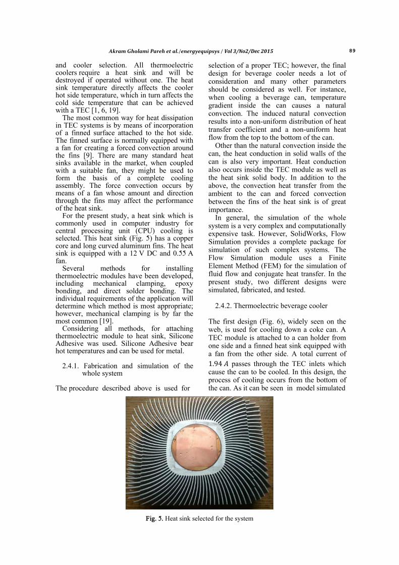
For the present study, a heat sink which is commonly used in computer industry for central processing unit (CPU) cooling is selected. This heat sink (Fig. 5) has a copper core and long curved aluminum fins. The heat sink is equipped with a 12 V DC and 0.55 A fan.
Several methods for installing thermoelectric modules have been developed, including mechanical clamping, epoxy bonding, and direct solder bonding. The individual requirements of the application will determine which method is most appropriate; however, mechanical clamping is by far the most common [19].
Considering all methods, for attaching thermoelectric module to heat sink, Silicone Adhesive was used. Silicone Adhesive bear hot temperatures and can be used for metal.
2.4.1. Fabrication and simulation of the
whole system
The procedure described above is used for
selection of a proper TEC; however, the final design for beverage cooler needs a lot of consideration and many other parameters should be considered as well. For instance, when cooling a beverage can, temperature gradient inside the can causes a natural convection. The induced natural convection results into a non-uniform distribution of heat transfer coefficient and a non-uniform heat flow from the top to the bottom of the can.
Other than the natural convection inside the can, the heat conduction in solid walls of the can is also very important. Heat conduction also occurs inside the TEC module as well as the heat sink solid body. In addition to the above, the convection heat transfer from the ambient to the can and forced convection between the fins of the heat sink is of great importance.
In general, the simulation of the whole system is a very complex and computationally expensive task. However, SolidWorks, Flow Simulation provides a complete package for simulation of such complex systems. The Flow Simulation module uses a Finite Element Method (FEM) for the simulation of fluid flow and conjugate heat transfer. In the present study, two different designs were simulated, fabricated, and tested.
2.4.2. Thermoelectric beverage cooler
The first design (Fig. 6), widely seen on the web, is used for cooling down a coke can. A TEC module is attached to a can holder from one side and a finned heat sink equipped with a fan from the other side. A total current of
passes through the TEC inlets which cause the can to be cooled. In this design, the process of cooling occurs from the bottom of the can. As it can be seen in model simulated
Fig. 5. Heat sink selected for the system

90 Akram Gholami Pareh et al./energyequipsys / Vol 3/No2/Dec 2015
in SolidWorks (Fig. 7), the TEC module is sandwiched between the finned heat sink and the can holder. A boundary condition is applied at the bottom of the heat sink to simulate the installed fan. The simulation and results of the experiment showed that this is not a suitable design.
Fig. 6. Experimental setup of the thermoelectric
beverage cooler
Fig. 7. Model of the thermoelectric beverage cooler in SolidWorks
2.4.3. Thermoelectric cup
To enhance the process of cooling, a new design was suggested and fabricated here which completely removed the drawbacks of the first design (Fig. 8). The modified model was simulated in SolidWorks and the results were same as estimations (Fig. 9).
Fig. 8. The experimental setup of the
thermoelectric cup
Fig. 9. Model of the thermoelectric cup in SolidWorks
3.Results and Discussion
3.1. Thermoelectric beverage cooler The temperature contours in the middle section of the model (Fig. 10) clearly showed that the system is not capable of cooling the water to the desired values, that is, about 5 . The contour plot at the bottom of the can holder (Fig. 11) showed that the temperature at the interface between the holder and the TEC module is less than 10 . The actual value in this study is about 4 . However, every coke can has a curved surface at its bottom. The shape of the lower surface provides a very negligible contact area with the holder. These results into a very weak heat transfer rate and all the cooling power goes into the environment, that is, waste of energy. On the other hand, in the model under study, the cooling process occurs from the bottom of

Akram Gholami Pareh et al./energyequipsys / Vol 3/No2/Dec 2015 91
the can. Therefore, the cold water remains at the bottom of the can and natural convection does not occur. The outcome of the process is a temperature gradient (Fig. 12) where the lower part of the can is colder than the upper part.
Fig. 10. Temperature contours in the middle
section of the thermoelectric beverage cooler
Fig. 11. Temperature contours on the can holder
in thermoelectric beverage cooler (bottom view)
Fig. 12. Temperature contours around the can in thermoelectric beverage cooler
The temperature contours around the heat sink (Fig. 13) shows another drawback of this design. The fin temperature was about 60 while in the designing process, it was assumed to be 30 . This happens because the TEC module is not working properly under its designed condition and the parasitic heat load from the environment is much, that is, more than what was estimated.
The simulation results were verified by an experimental test by the setup shown in Figure 6. The simulation results showed that the water temperature inside the can reaches around 14 . The experimental test showed that the water temperature is about 15 to 17 . The consistency between the simulation and the experiment verifies the simulation results.
The above simulation results show that such configuration is not practical, mainly due to the (a) negligible surface contact between the can bottom and (b) undesired temperature gradient that prevents natural convection.
Fig. 13. Temperature contours around the heat sink in thermoelectric beverage cooler
3.2. Thermoelectric cup
The design of the thermoelectric cup was modified to address some of the drawbacks of the current design. In the proposed model, the TEC module has been moved to the top of the cup in order to enhance the natural convection discussed above. On the other hand, a flat surface has been constructed on the cup’s wall in order to increase the contact surface area. The size of the flat area was determined such that the whole TEC would be fit on that surface. These modifications could help to eliminate the difficulties mentioned above.
The temperature contours obtained from the numerical simulation (Fig. 14) showed that the proposed design is capable of decreasing the water temperature down to the desired values. The temperature contours on the outer surface of the cup’s wall (Fig. 15) showed

92 Akram Gholami Pareh et al./energyequipsys / Vol 3/No2/Dec 2015
that, the contact interface of the cup and the TEC module reached below zero Celsius. This can be seen in the temperature contours on a horizontal surface located at the middle height of the cup (Fig. 16) where the temperature of water is almost uniform. The water temperature becomes uniform mainly due to
the induced natural convection (Fig. 17). It should be noted that the induced natural convection is a three-dimensional phenomenon (Fig. 18). The induced natural convection plays an important role in heat and mass transfer resulting in a uniform and efficient cooling.
Fig. 14. Temperature contours in the middle section of the horizontal plane in thermoelectric cup
Fig. 15. Temperature contours on the cup’s wall in thermoelectric cup
Fig. 16. Temperature contours in the middle section of the vertical plane in thermoelectric cup
Akram Gholami Pareh et al./energyequipsys / Vol 3/No2/Dec 2015 93
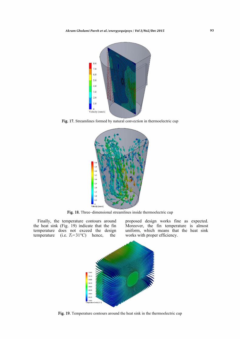
Fig. 17. Streamlines formed by natural convection in thermoelectric cup
Fig. 18. Three–dimensional streamlines inside thermoelectric cup
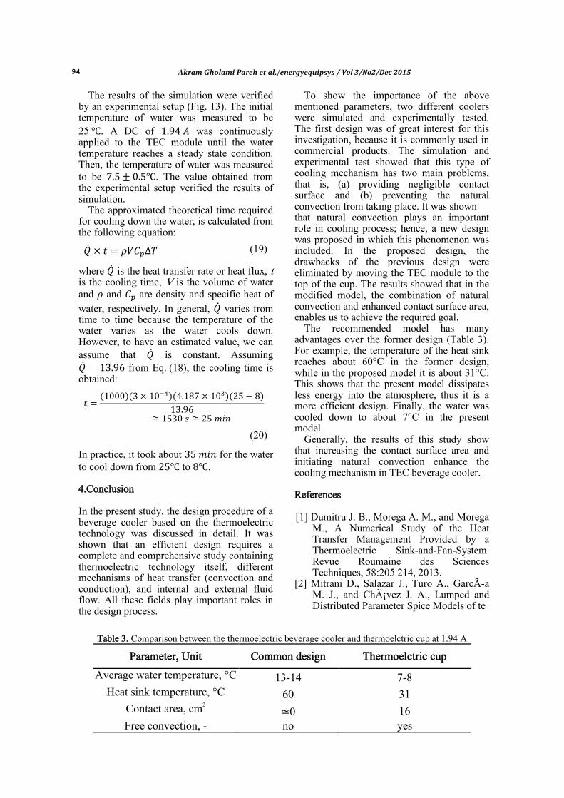
Finally, the temperature contours around
the heat sink (Fig. 19) indicate that the fin temperature does not exceed the design temperature (i.e. Th= 31°C) hence, the
proposed design works fine as expected. Moreover, the fin temperature is almost uniform, which means that the heat sink works with proper efficiency.
Fig. 19. Temperature contours around the heat sink in the thermoelectric cup
94 Akram Gholami Pareh et al./energyequipsys / Vol 3/No2/Dec 2015
The results of the simulation were verified by an experimental setup (Fig. 13). The initial temperature of water was measured to be 25 . A DC of was continuously applied to the TEC module until the water temperature reaches a steady state condition. Then, the temperature of water was measured to be . The value obtained from the experimental setup verified the results of simulation.
The approximated theoretical time required for cooling down the water, is calculated from the following equation:
(19)
where is the heat transfer rate or heat flux, t is the cooling time, V is the volume of water and and are density and specific heat of
water, respectively. In general, varies from time to time because the temperature of the water varies as the water cools down. However, to have an estimated value, we can assume that is constant. Assuming from Eq. (18), the cooling time is obtained:
( )( )( )( )
(20)
In practice, it took about for the water to cool down from to . 4.Conclusion In the present study, the design procedure of a beverage cooler based on the thermoelectric technology was discussed in detail. It was shown that an efficient design requires a complete and comprehensive study containing thermoelectric technology itself, different mechanisms of heat transfer (convection and conduction), and internal and external fluid flow. All these fields play important roles in the design process.
To show the importance of the above mentioned parameters, two different coolers were simulated and experimentally tested. The first design was of great interest for this investigation, because it is commonly used in commercial products. The simulation and experimental test showed that this type of cooling mechanism has two main problems, that is, (a) providing negligible contact surface and (b) preventing the natural convection from taking place. It was shown that natural convection plays an important role in cooling process; hence, a new design was proposed in which this phenomenon was included. In the proposed design, the drawbacks of the previous design were eliminated by moving the TEC module to the top of the cup. The results showed that in the modified model, the combination of natural convection and enhanced contact surface area, enables us to achieve the required goal.
The recommended model has many advantages over the former design (Table 3). For example, the temperature of the heat sink reaches about 60°C in the former design, while in the proposed model it is about 31°C. This shows that the present model dissipates less energy into the atmosphere, thus it is a more efficient design. Finally, the water was cooled down to about 7°C in the present model.
Generally, the results of this study show that increasing the contact surface area and initiating natural convection enhance the cooling mechanism in TEC beverage cooler.
References [1] Dumitru J. B., Morega A. M., and Morega
M., A Numerical Study of the Heat Transfer Management Provided by a Thermoelectric Sink-and-Fan-System. Revue Roumaine des Sciences Techniques, 58:205 214, 2013.
[2] Mitrani D., Salazar J., Turo A., GarcÃa M. J., and Chávez J. A., Lumped and Distributed Parameter Spice Models of te
Table 3. Comparison between the thermoelectric beverage cooler and thermoelctric cup at 1.94 A
Parameter, Unit Common design Thermoelctric cup
Average water temperature, °C 13-14 7-8 Heat sink temperature, °C 60 31
Contact area, cm2 ≃0 16 Free convection, - no yes

Akram Gholami Pareh et al./energyequipsys / Vol 3/No2/Dec 2015 95
Devices Considering Temperature Dependent Material Properties. In Thermal Investigation of ICs and Systems, 2007. THERMINIC 2007. 13th International Workshop on, Sep. (2007) 202--207.
[3] Goldsmid H. J., Introduction to Thermoelectricity Heidelberg: Springer, Internet resource, (2010).
[4] Rowe M., CRC Handbook of Thermoelectrics, CRC Press LLc, (1995).
[5] Ioffe A. F., Semiconductor Thermoelements and Thermoelectric Cooling. Infosearch Limited, London, (1957).
[6] Enescu D. and Virjoghe E. O., A Review on Thermoelectric Cooling Parameter and Perfirmance. Renewable and Sustanable Enrgy Reviews. 38 (2014) 903-916.
[7] Bo L. and Yawen C., Potable Beverage can Cooler. Bachelor's thesis, Saimaa University of Applied Sciences, Lappeenranta Technology, Mechanical Engineering and Production Technology, 2010.
[8] Thielmann J., Thermoelectric Cooling Technology, Will Peltier Modules Supersede the Compressor?
[9] Dousti M. J. and Pedram M., Power-Aware Deployment and Control of Foeced-Convection and Thermoelectric Coolers. Proceedings of the 51st Annual Design Automation Conference, (2014)1-6, ISBN: 978-1-4503-2730-5.
[10] Zhao D. and Tan G., A Review of Thermoelectric Cooling: Materials, and Applications. Applied Thermal Engineering. Vol.66, No.1–2, May (2014), 15–24.
[11] Lineykin S. and Ben-Yaakov S., A Simple and Intuitive Graphical Approach to the Design of Thermoelectric Cooling Systems. In Power Electronics Specialists Conference, June (2006). PESC '06. 37th IEEE, 1-5.
[12] Zebarjadi M. Electronic Cooling Using Thermelectric Devices. Applied Physics Letters 106, 203506 (2015); doi: 10.1063/1.4921457.
[13] Nolas G. S., Sharp J., and Goldsmid J., Thermoelectrics, Basic Principles and New Materials Developments}. Springer-Verlag, (2001).
[14] Brown D. R., Fernandez N., Dirks J. A., and Stout T. B., The Prospects of Alternatives to Vapor Compression
Technology for Space Cooling and Food Refrigeration Applications. Technical Report, Pacific Northwest National Laboratory (PNL). U.S. Department of Energy, (2010).
[15] G Snyder. J. and Toberer E. S., Complex Thermoelectric Materials. Nature Materials, (2008)7:105-114.
[16] Rosa A. V., Fundamentals of Renewable Energy Processes, Elsevier Academic Press, (2005).

![Conjugate heat transfer in OpenFOAM - Chalmershani/kurser/OS_CFD_2016/TuroValikangas/Repo… · problem. [2] 1.2 ... For the conjugate heat transfer problems in OpenFOAM, a conjugate](https://img.pdfslide.us/doc/110x75/5a7a0bbc7f8b9adf228cbdf0/conjugate-heat-transfer-in-openfoam-hanikurseroscfd2016turovalikangasrepoproblem.jpg)