Embed Size (px)
Citation preview

EFFECT OF COMPOSITION AND PROCESSING ON THE TmRMAL FATIGUE AND TOUGHNESS OF
HIGH PERFORMANCE DIE STEELS
Year 1 Report
John F. Wallace Yumin Wang
David Schwam
Case Western Reserve University Cleveland, Ohio
D!STRIBUllON OF THIS DOCUMENT IS UNUMITEP
RFCEIVED APR 0 9 1997
O S T I
Performed under Contract No. DOE/DE-FC07-95IDl3360
For
US Department of Energy Assistant Secretary for Energy Efficiency and Renewable Energy Office of Industrial Technology Washington D.C.
MASTE
June 1996

DISCLAIMER
This report was prepared as an account of work sponsored by a n agency of the United States Government. Neither the United States Government nor any agency thereof, nor any of their employees, make any warranty, express or implied, or assumes any legal liabili- ty or responsibility for the accuracy, completeness, or usefulness of any information, appa- ratus, product, or process disclosed, or represents that its use would not infringe privately owned rights. Reference herein to any specific commercial product, process, or sem'ce by trade name, trademark, manufacturer, or othenvise does not necessarily constitute or imply its endorsement, recommendation, or favoring by the United States Government or any agency thereof. The views and opinions of authors expressed herein do not necessar- ily state or reflect those of the United States Government or any agency thereof.
I'

DISCLAIMER
Portions of this document may be illegible in eiettrOnic image products. Images are produced from the best available original document.

EFFECT OF COMPOSITION AND PROCESSING ON THE THERMAL FATIGUE AND TOUGHNESS OF
HIGH PERFORMANCE DIE STEELS
Year 1 Report
John F. Wallace Yumin Wang
David Schwam
Case Western Reserve University Cleveland, Ohio
Performed under Contract No. DOE/DE-FC07-95IDl3360
For
US Department of Energy Assistant Secretary for Energy Efficiency and Renewable Energy Office of Industrial Technology Washington D.C.
June 1996
lfi DISTRiBUflON OF THiS DOCUMENT IS UMLIMiTED

LIST OF CONTENTS
ABSTRACT
1.0 INTRODUCTION
2.0 PROPERTIES OF DIES AND DIE STEELS
2.1 Die Failure Modes 2.2 Thermal Stresses 2.3 Thermal Fatigue Resistance 2.4 Effects of Metallurgical Variables on the Die Life 2.5 Effect of Electro-Discharge Machining (EDM)
3. RESEARCH PLAN
3.1 Effect of Steel Chemistry 3.2 Effect of Cooling Rates 2.5 Effect of Electro-Discharge Machining (EDM)
4. EQUIPMENT AND EXPERIMENTAL PROCEDURES
5.0 RESULTS AND DISCUSSION
5.1 Selection of the Die Steels 5.2 Optimization of Heat Treatment 5.3 Heat Treating of the Thermal Cycling and the Charpy Samples 5.4 Charpy V-notch Impact Testing of the Steels 5.5 Thermal Cycling Evaluation of the Steels 5.6 Effect of EDM 5.7 In-Plant Evaluation
6. SUMMARY AND INTERIM CONCLUSIONS
7. FUTURE WORK
8. REFERENCES
1
3
4
4 5 6 8 10
12
12 15 16
17
20
20 23 44 44 53 63 63
64
65
66

ABSTRACT
The goal of this project is to extend the lifetime of dies for die casting by 20%. Since the die contributes about 10% to the cost of die cast parts, such an improvement in lifetime would result in annual savings of over $200 Million dollars. This is based on the estimated annual die production of one Billion dollars in the US.
The major tasks of this two year project are:
Evaluate NEW DIE STEEL COMPOSITIONS that have been developed for demanding applications and compare them to Premium Grade H-13 die steel.
Optimize the AUSTENITIZNG TREATMENT of the new composition. Assess the effects of fast, medium and slow COOLING RATES DURING HEAT TREATMENT, on the thermal fatigue resistance and toughness of the die steel.
Determine the effect of ELECTRO-DISCHARGE MACHINING (EDM) on the thermal fatigue resistance and impact properties of the steel.
Select demanding components and conduct IN-PLANT TESi7NG by using the new steel. Compare the performance of the new steel with identical components made of Premium Grade H-13.
The immersion thermal fatigue specimen developed at CWRU is being used to determine resistance to heat checking, and the Charpy V-notch test for evaluating the toughness. The overall result of this proiect will be identification of the best steel available on the market and the best processing methods for aluminum die casting dies.
This is an interim report for year I of the project.
1

Four different steels, KDA-1, Chromo-N, QRO-90 and Premium Grade H-13 have been tested so far for thermal fatigue resistance and toughness. KDA-1 and QRO-90 are lower in chromium and vanadium contents and higher in molybdenum than conventional H-13 die steel, which are believed to provide better thermal fatigue resistance and toughness. KDA-1 has a lower silicon content that should presumably minimize interdendritic segregation.
The optimum heat treatment processing has been determined for each steel with respect to austenitizing temperature (1 875°F- 1925°F) and tempering conditions (double tempering for two hours at 1100°F. Chromo-N is less temper resistant and should be tempered for one hour at 1040°F and one hour at 1000°F to retain an acceptable hardness value of 45-46Rc.
The thermal cycling samples have been quenched under three cooling conditions:
a. Fast quench using an oil quench at Lindberg Heat Treating in Solon, Ohio.
b. Medium quench using 5,7 and 10 bar nitrogen gas cooling at FPM Heat Treating in Chicago.
c. Slow quench using a 1 bar nitrogen cooling at Universal Heat Treating in Cleveland, Ohio.
The effect of the quenching rate has been evaluated. The results indicate that samples quenched at the fastest rates exhibit the best resistance to thermal fatigue.
KDA-1 has been identified as superior in performance compared to Premium Grade H- 13. Our results clearly demonstrate that the thermal fatigue resistance of KDA-1 is superior to Premium Grade H-13. We regard this as a major accomplishment in the project, and an important breakthrough in the die materials research. The superior performance is attributed to the lower silicon and vanadium present in this steel. This benchmarking study was initiated with the premise that modem 90's steel making technology may be able to produce
2

hot die steels that are superior to the Premium Grade H-13 commonly used in the US. The results of the thermal cycling test demonstrate this to be true.
The effect of electro-discharge machining on the thermal fatigue properties of the die steels is currently under evaluation.
Along with the continuation of the in-house testing program, we are planing the details of the in-plant evaluation. The in-plant part of the evaluation has to be conducted in a production environment. It is realized that under production conditions, we need to be sensitive to the schedules and constrains of the plant, and so the plans have to be mutually agreeable.
1. INTRODUCTION
Die casting is an economical way to produce large quantities of complicated-shaped products of light metals with high precision''). In the process molten metal is injected under high velocity into a water cooled metallic mold or die. It solidifies as a net shape When solidification is completed and the die casting has cooled sufficiently, the die is opened and the part is ejected by mechanically activated pins. The die is subsequently exposed to air, sprayed with a lubricant, closed and molten metal is again injected into the die to complete the cycle. The major economic advantages of the process is that it can produce castings with close dimensional tolerances, smooth surface finishes and fine, intricate details at high production rates. However, due to thermal and mechanical cyclic loading and reactions with entering molten
metal, die casting dies are subject to severe damage: erosion, chemical attack, gross cracking and thermal cracking(+'4). Damage to the dies can increase production cost and reduce casting quality. With the increasing amount of die casting of aluminum the damage to the dies becomes a serious problem. The advantages of the die casting are offset to some extent by the high cost of the die depending on its intricacy and complexity, the die can even cost more than the machinery used to operate it (5*6). Die casting with aluminum alloys requires die steels with higher strength and toughness than that used for lower melting temperature metals. This steel is both more expensive and more difficult to machine. In aluminum die casting, typical die life ranges from 100,000 to 150,000 casting (15s16). As the number of parts that can be cast from a
3
single die increase, the process becomes more economical. Additional costs are incurred when the production of castings is interrupted or die failure necessitates repairs. Therefore, increasing the production life of a die through die steel improvement and die failure prevention can make a major contribution toward the profitability of the die casting operations.
2. PROPERTIES OF DIES AND DIE STEELS
2. 1 Die Failure Modes
Failure modes identified for aluminum die casting dies are mechanical erosion, chemical attack, gross cracking and thermal fatigue cracking. Two types of mechanical erosion have been
over the die surface. Cavitation erosion is the result of the collapse of gas bubbles in the molten alloy near the die surface. This causes high pressures at the surface, resulting in stress induced strain at the die surface(6*'2). The repetitive straining of the surface is a source of mechanical fatigue and adds to thermally induced fatigue.
defined(S6*"-'5) . W ear erosion is caused by the abrasive action of the molten metal as it flows
Chemical attack can occur through compositional changes in the die surface by means of decarburization of steel dies. This decarburization degrades the strength and ductility of the die surfaces and results in accelerated thermal fatigue('*). Decarburization is the loss of carbon at the die surface during heat treatment or production use and results in a lower surface hardness.
The surface of the die is also tempered by its cyclic exposure to higher temperatures. This tempering plus decarburization can reduce the hardness to about 35 Rockwell C while the die interior has an optimum hardness of 46-48 Rockwell C(6*9-'1). Because the surface has a strength below that needed for the die casting operation, early heat checking may occur. Oxidation or corrosion is also related to heat checking during both crack initiation and crack propagation stages. Another form of attack is chemical adhesion of the cast metal to the die surface, also known as soldering. This can cause damage to the die as well as the casting.
4

Gross cracking is catastrophic in nature and not as directly related to the surface of the die cavities. It is produced by thermal and mechanical stresses on the die. It may require that the die be replaced because of extensive or complete cracking@). These cracks frequently occur at low temperatures or in die steels with low fracture toughness. They also initiate from deep heat checks. Thermal stresses result from imbalanced heating or cooling of the die; mechanical stressing of the die may exceed the fracture strength(6i''! Both of these causes can be minimized by avoiding severe thermal stresses by proper die support and by increasing the fracture toughness of the die material.
Heat checking, a result of thermal fatigue, is the most frequent cause of the failure of aluminum die casting dies. Thermal fatigue is caused by the cyclical temperature fluctuations present in the die casting process. It induces the stress and strain conditions that occur when the thermal expansion or contraction of a section is restrained by the surrounding material. When such stresses exceed the elastic limit or yield strength of the die, the steel surface can upset, introducing tensile stresses on the die surface. A repeated series of heating and cooling of the surface can produce a fine network of cracks in the die surface. This is recognized as heat checking which is also called thermal fatigue cracking or craze cracking. The cracking starts after a number of die casting cycles (initiation) and grows at an accelerated rate (propagation). Cracks initiate and propagate in both an intra- and inter-granular manner and are filled with
As mentioned before, corrosion is involved in the initiation and propagation of heat checks. The die is exposed to an oxidizing atmosphere which can cause corrosion pits that are filled with oxides. Because the oxides occupy a large volume than the metal that was previously present, a wedging action occurs which contributes to crack propagation(".'7).
2.2 Thermal Stresses
The thermal stresses that occur in the die develop from the thermal gradient across the die section. The thermal gradient forms as a result of the heating and cooling of the surface during the injecting, ejecting and lubricant spraying stages of the casting cycle. When the molten aluminum is injected into the die, the die surface heats up considerably compared to the cooler underlying mass of the die. This sets up an initially steep thermal gradient. As a result, the
5
surface expands more than the interior and because the interior is more massive, it prevents the surface from expanding. As the increase of this restraint, the surface is placed under compression. The high temperature lowers the yield strength of the material therefore the compressive strains become plastic. The surface temperature decreases rapidly as heat conducts into the lower layers. When the casting is ejected, cooling through the surface and the spray of die lubricants further decrease the surface temperature('*). If the surface cools more rapidly than the interior, the Compressive strains are relieved and tensile strains may be created.
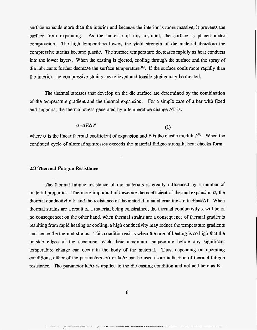
The thermal stresses that develop on the die surface are determined by the combination of the temperature gradient and the thermal expansion. For a simple case of a bar with fixed end supports, the thermal stress generated by a temperature change AT is:
(1) a=aEAT
where a is the linear thermal coefficient of expansion and E is the elastic modulus('g). When the continued cycle of alternating stresses exceeds the material fatigue strength, heat checks form.
2.3 Thermal Fatigue Resistance
The thermal fatigue resistance of die materials is greatly influenced by a number of material properties. The more important of these are the coefficient of thermal expansion a, the thermal conductivity k, and the resistance of the material to an alternating strain &=OAT. When thermal strains are a result of a material being constrained, the thermal conductivity k will be of no consequence; on the other hand, when thermal strains are a consequence of thermal gradients resulting from rapid heating or cooling, a high conductivity may reduce the temperature gradients and hence the thermal strains. This condition exists when the rate of heating is so high that the outside edges of the specimen reach their maximum temperature before any significant temperature change can occur in the body of the material. Thus, depending on operating conditions, either of the parameters da or k d a can be used as an indication of thermal fatigue resistance. The parameter k d a is applied to the die casting condition and defined here as K.
6
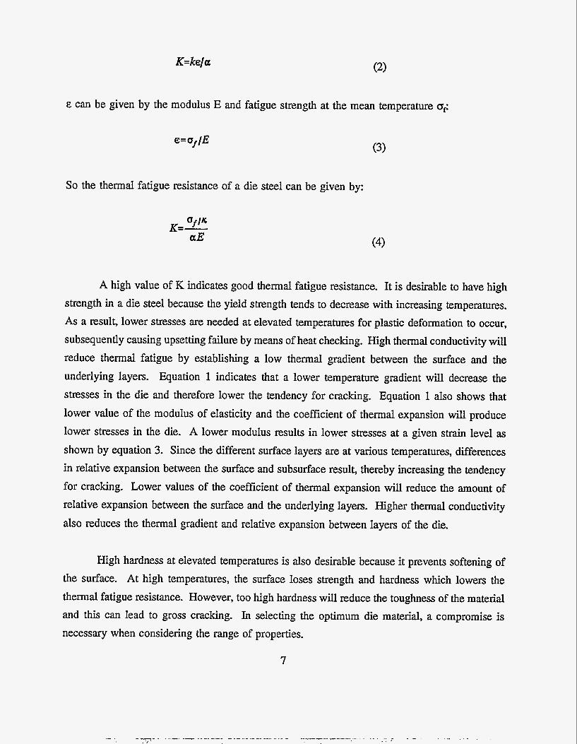
K=ke/a
E can be given by the modulus E and fatigue strength at the mean temperature 0,:
e= ur/E
So the thermal fatigue resistance of a die steel can be given by:
(3)
A high value of K indicates gooc, therma fatigue resistance. It is desirable to have high strength in a die steel because the yield strength tends to decrease with increasing temperatures. As a result, lower stresses are needed at elevated temperatures for plastic deformation to occur, subsequently causing upsetting failure by means of heat checking. High thermal conductivity will reduce thermal fatigue by establishing a low thermal gradient between the surface and the underlying layers. Equation 1 indicates that a lower temperature gradient will decrease the stresses in the die and therefore lower the tendency for cracking. Equation 1 also shows that lower value of the modulus of elasticity and the coefficient of thermal expansion will produce lower stresses in the die. A lower modulus results in lower stresses at a given strain level as shown by equation 3. Since the different surface layers are at various temperatures, differences in relative expansion between the surface and subsurface result, thereby increasing the tendency for cracking. Lower values of the coefficient of thermal expansion will reduce the amount of relative expansion between the surface and the underlying layers. Higher thermal conductivity also reduces the thermal gradient and relative expansion between layers of the die.
High hardness at elevated temperatures is also desirable because it prevents softening of the surface. At high temperatures, the surface loses strength and hardness which lowers the thermal fatigue resistance. However, too high hardness will reduce the toughness of the material and this can lead to gross cracking. In selecting the optimum die material, a compromise is necessary when considering the range of properties.
7

2.4 Effects of Metallurgical Variables on The Die Life
The metallurgical variables have great influence on the die life of a die steel through the effects on both thermal fatigue and fracture toughness of the steel. It is established that the austenitizing temperature is an important metallurgical variable(*s"20-2. When the austenitizing temperature is increased from the conventional hardening temperature of 1800°F upward to 2200°F for H-13 steel, a steady improvement in the resistance to heat checking occurs. This improvement is attributed to the greater resistance to tempering because of the increased solution of alloy carbides. However, above 2000°F, significant grain growth occurs because less amounts of carbides are available for the inhibition of grain growth. The Charpy impact values and the fracture toughness decrease rapidly as the austenitizing temperature increases above 2000"F@*2022~. Considering both the thermal fatigue and fracture toughness behavior, a 1900°F temperature may well be the best for H-13 steel all around austenitizing temperature. The optimum microstructure for the die steel is a fine martensitic structure obtained with rapid cooling or a completely bainitic structure@"). An optimum hardness level should be reached by quenching and tempering. Higher hardness is too brittle with lower fracture toughness and lower hardness lacks sufficient strength with lower thermal fatigue resistance.
Since retention of high strength and toughness governs thermal fatigue behavior, any change in local chemistry during heat treatment either through decarburization or carburization may affect thermal fatigue behavior. Therefore, the carbon content of the steel at the surface and its associated hardness level has a marked effect on thermal fatigue life. Accordingly, decarburization is detrimental and causes premature heat checks because the low carbon layer has a lower strength(7i923i24). On the other hand, carburization is also detrimental and exhibits a lower heat checking resistance because the surface layer does not have enough toughness@'*w. However, it was reported that some carburization can increase thermal fatigue life(23). Therefore, it is concluded that decarburization and heavy carburization cause premature heat checking and slight carburization may have little effect!20).
Thin hard nitride and carbide coating techniques have been developed and used by Japanese aluminum die casting industry(26). The coated layer has a thickness less than 10 or 20 pm with extremely high hardness, HV2000-3000. It is claimed that the thin hard coating process,
8

Chemical Vapor Deposition (CVD), Physical Vapor Deposition (PVD), Plasma Chemical Vapor Deposition (PCVD) and Thermal-Reactive Deposition and Diffusion (TRDD), can provide remarkable improvement of the surface properties of steels highly associated with damage on die casting dies. Many new methods for producing unique modifications of material surfaces have been developed in the past decades(2a. However, evaluation methods of coated dies are not sufficiently sophisticated to fully characterize phenomena inherent in die casting and asses the contribution of the coating.
Nonmetallic inclusions are generally considered undesirable constituents and are usually required to be held to a minimum within practical limits(24). The use of premium grade H-13 steel provided by Vacuum Arc Remelting (VAR) and Electro-Slag Remelting (ESR) previously has resulted in a significant improvement of heat checking resistance.
Die steels may have different structures depending on the cooling rate from the austenitizing temperature(28). The final microstructure should be a uniform tempered martensite without carbides precipitated at grain boundaries and undissolved carbides. If the steel is allowed to cool slowly during hardening, the thermal fatigue life and Charpy impact energy values are reduced because of heavy carbide precipitation at grain boundaries(20,U28). An idealized microstructure should consist of tempered martensite within which are small, rounded, and evenly dispersed pro-eutectoid carbides and with a finer scale carbide dispersion within the martensite product itself. Such a structure can be obtained if the prior annealed structure is such that all the precipitated and primary alloy carbides are evenly distributed within a fine grained ferrite matrix. This means that the prior structure should be homogeneous and free of carbide stringers and severe alloy banding. The widely used specifications to ensure high homogeneity of die steels based on annealed microstructure ratings are NADCA #207-90 and Chrysler NP-2080’29*30). These annealed structure ratings are primarily based on the homogeneity of carbide distribution which directly relate to the impact toughness and thermal fatigue resistance of the die steel^(^'*^^). A good annealed structure provides about 14 ft-lb room temperature impact toughness after it is austenitized at 1875°F and double tempered to 44-46 HRC, while a poor prior structure has only half the value under the same heat treatment!31). A new acceptance standard for die steels has been developed and recently suggested by B. Gehricke et al.(33).
9

Dies for aluminum die casting require high thermal fatigue resistance and toughness properties of the die steels. Carbide precipitation on grain boundaries reduce the properties Changes in the heat treatment do not totally suppress the existence of carbide precipitation, so changes of the alloy composition are needed to reduce the carbide content and the intensity of carbide precipitation on grain boundaries. Based on H-13 die steel, the basic carbide forming elements are carbon, chromium, molybdenum and vanadium. One of the objectives of this study is to optimize the steel composition for better die steels.
2.5 Effect of Electro-Discharged Machining(EDM)
EDM is widely used in die manufacturing. It is reported to be used in about one half of modern dies. This process is capable of producing fine intricate details such as holes with diameters as small as 0.002 inch(35). Because the process is independent of work piece hardness, it has the ability to machine fully hardened tool steels without the use of hard tools. This minimizes or eliminates adjustments due to any associated distortions. While conventional machining processes require hard carbide tools, the electrodes used in EDM are commonly made from graphite or copper which are soft and easier to machine(36).
The EDM process removes metal by a series of electrical spark discharges. The process affects the microstructure of the surface layers of the work In die steels, three layers form in the EDM surface as shown in Figure 2.1: the melted layer, the heat affected layer, and c) the unaffected parent material. The melted layer is present as a brittle, non-etchable white layer containing cracks(22i2539~37gspl! This is the material that was melted and rapidly resolidified on the surface and not flushed away by the dielectric fluid. This layer is infiltrated with carbon which can originate from the electrode and from hydrocarbons that form from the dielectric when it breaks Depending on the machining parameters and the work piece material, the white layer may range in thickness from 8 to 15 microns.
The zone under the white layer is also affected by the heat produced during EDM and consists of a tempered zone and rehardened zone. In the rehardened zone, the temperature produced by the EDM process has reached the austenitizing range. During the rapid
10

9 MELTED AND SOLIDIFIED
UNTEMPERED MARTENSITE
TEMPERED LAYER
UNAFFECTED BASE METAL
DEPTH (micro n s)
8-25
25-40
40-85
HARDNESS (Rc)
56-58
50-54
34-43
46-48
Fig. 2.1: Surface layers on surface of EDMed surface of H-13 steel
cooling from this temperature, hard brittle untempered martensite is formed. In the regions further below the surface, the temperatures attained are not as high and tempering occurs. The resulting steel in this layer is softer than the original hardness obtained by heat treatment. The heat affected zone has a thickness that can reach up to 85 micron^(^^.^).
Although EDM does not exert mechanical forces on the work piece, it is evident that residual stresses exist in EDM surfaces. High tensile stresses have been measured at the surface. These stresses fall rapidly with increasing depth to a relatively low value and then change at further depth to small compressive s t r e s ~ e s ~ ~ " ~ ) . The stresses arise mainly as a result of the thermal contraction of resolidified metal or recast layer onto the parent met~tl(~"~). This induces plastic deformation and tensile stresses. The thermal cycle at the surface causes steep temperature gradient normal to the surface in a somewhat similar manner as thermal conditions that occur at the die surface during the casting process. This can contribute to the development of residual stresses in the die(43).
11

The higher hardness of the EDM surface could improve the wear resistance of the material(M). However, the existence of the hardened and softened layers and the residual stresses could well reduce the fatigue resistance of the die. An EDM condition that provided a f i e surface finish slightly improved the thermal fatigue life over that for a rough surface finish. However, greater improvements in thermal fatigue life were achieved by removal of the damaged layer and stress relief. A demonstrated that the tensile residual stresses could be replaced by compressive stresses with grit polishing the surface of the steel with a thin recast or white layer. This thin white layer was obtained by reducing the spark energy of the EDM transfer on the final metal removal process. This white layer should be removed mechanically.
The effect of the EDM treatment on the die can be partially offset by tempering. The untempered martensitic layer can be softened by tempering slightly below the temperature used in the initial heat treatment. Tempering will also relieve any tensile stresses at the surface that are probably caused by the solidification process. However, these treatments can not restore the hardness of the overtempered layer (45*47).
3. RESEARCH PLAN
3.1 Effect of Steel Chemistry
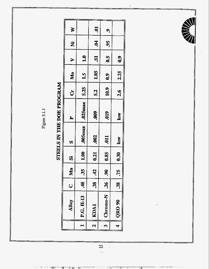
A new type of steels, KDA, that is reported to have provided improved die life over H-13 steel in equivalent casting operations has been brought to the attention of U.S. industries by both Japanese and German sources. It is claimed that these steels whose composition varies to some extent, have significantly extended the life of squeeze casting dies. These steels have higher resistance to softening and may have higher high temperature strength than that of H-13. They are all produced to carbide, microstructure, sulfur and phosphorous levels and inclusion limitations that parallel those of premium grade H-13. While the chemical analysis of these steels varies somewhat from one source to another, it is reported to be lower in chromium and vanadium and higher in molybdenum than conventional H-13 steel as demonstrated in Table 1. Another new type of hot-work tool steels, QRO-90, produced by a Swedish company, Uddeholm Corporation, is claimed to be superior to H-13 steel in the die casting die application. Like
12

KDA-1, QRO-90 is lower in chromium and vanadium and higher in molybdenum, and also little lower in carbon than H-13 as given in Table 1.
Table 1. The composition of various steels
These steels are heat treated in a similar manner as premium grade H-13: rapid cooling from a high austenitizing temperature, double or triple tempering and avoiding surface damage during processing. The reported properties are superior to those of H-13 steel. Data on the resistance to tempering, particularly with high austenitizing temperatures of 1900°F indicates these steels are significantly more temper resistant than the H-13 steel. The resistance to tempering is a very important consideration in resistance to thermal fatiguecraccing.--De . ~ .~
~~
surface of H-13 dies that have suffered severe thermal fatigue cracking have always been softened into the 30's Rockwell C hardness range by this tempering action.
. . . -- ~ - ~ - ~ ~~
Die steels of the general KDA-1 composition have been tested for thermal fatigue cracking by a severe test that involves heating and quenching in water. While this test may not be as directly relevant to die casting dies as the immersion test described elsewhere in this report, it shows that the new composition has twice the heat checking resistance as that of H-13. It is noted that the results of the heat checking tests show better resistance at higher hardness for both H-13 and KDA-1. It is also noted that the lower chromium and vanadium steel with higher molybdenum content are used at hardness up to 50-52 Rockwell C. The use of the new steel at the higher hardness may provide a partial rationalization for its success. It has been shown in previous work conducted at CWRU(43 that the resistance to thermal fatigue cracking improved at hardness into the low Rockwell C 50 range. However, the significant loss in toughness that occurred at these higher hardness with H13 did not permit the dies to be used at this hardness level. In the case of the new steel, the reported room temperature Charpy V-notch impact test results at 52 Rockwell C are slightly higher than for H13 steel at 46 Rockwell C hardness. This indicates that the new steel can be employed at the higher hardness without any decrease in resistance to gross cracking.
13

Molybdenum is an effective element in improving hardenability and high temperature strength. It retards the softening of martensite at all tempering temperatures. Above 1000°F (540"C), it partitions to the carbide phase and thus keeps the carbide particles small and numerous. In addition, molybdenum reduces susceptibility to tempering embrittlement. Chromium, like molybdenum, is a strong carbide-forming element that can be expected to retard the softening of martensite at all temperatures. Also, by substituting chromium for some of the iron in cementite, the coalescence of carbides is retarded. As a result of the stability of chromium carbide at lower austenitizing temperature, its hardenability becomes less effective. Vanadium is a stronger carbide former than molybdenum and chromium and can therefore be expected to have a much more potent effect at equivalent alloy levels. The strong effect of vanadium is probably due to the formation of an alloy carbide that replaces cementite-type carbides at higher tempering temperatures and persists as a fine dispersion up to the A1 temperature. The steel must be austenitized at a sufficiently high temperature and for a sufficient length of time to ensure that the vanadium is in solution and thus able to contribute to hardenability. Moreover, solution is possible only if small amounts of vanadium are in the steel. Excess content will leave large carbide particles on the grain boundaries in the quenching and tempering steel which will lower the toughness of the steel. High austenitizing temperatures can completely dissolve the carbides in H13 steel. But too high austenitizing temperature will enhance grain growth rapidly.
In view of above data, some of these new steels were tested for thermal fatigue resistance using the immersion test that has proved to be a good indicator of die life". The Charpy V-notch fracture energy at the temperature range of interest, including the transition temperature was employed to measure the gross cracking resistance. These tests were conducted at hardness levels of 46 to 52 Rockwell C to cover the range of interest. The processing and testing of the new steel followed the procedures recommended for premium grade H13 die steel. The microstructure of these steels at different heat treatment stages and conditions was determined and the effect of microstructure on properties was monitored. Based on the research progress and new steel availability, as many as possible of these steels will be tested. The goal is to find the optimum composition for aluminum die casting die steels with the optimum heat treatment.
14

3.2. Effect of Cooling Rates
In a previous project CWRU demonstrated(48), as shown in Figure 1, that cooling rates of about 50°F/minute from the austenitizing temperature produced fairly high impact resistance and a tempered bainite structure with some grain boundary carbides. The bainitic matrix structure with some grain boundary carbides obtained by these intermediate cooling rates may be capable of producing long lasting dies without requiring the faster cooling rate needed to obtain a martensitic structure. This slower cooling rate is more attainable in vacuum furnaces and avoids much of the distortion and heat cracking that could occur at faster rates of cooling.
CO-OUNG AATE---d.g.F. D W mln.
Fig. 3.2: Effect of quench rate on impact toughness of H-13 die steel at 46 HRC
However, the previous studies had shown that the optimum combination of properties was only obtained by more rapid cooling rates that assured the rapid cooling to martensite. This leaves unanswered the question about the thermal fatigue properties of these bainitic structures. This portion of the study is designed to provide the answer to this question.
The procedure that was followed to prepare a series of the thermal fatigue immersion specimens is described elsewhere in the report. The specimens were produced from the same forged billet of steel with identical orientation in the sane direction in that billet. Some of these specimens were processed by oil quenching from the austenitizing temperature with allowance for removing any surface skin where the composition could be affected by exposure to elevated temperatures. Other specimens were brought to final dimensions, heat treated in vacuum
15

furnaces and cooled at various rates from the austenitizing temperatures. The rates of cooling include those that provide a large amounts of grain boundary carbides, as well as bainitic and martensitic matrixes with fewer carbides. These specimens were tested and their relative thermal fatigue resistance compared.
Charpy V-notch tests were also prepared and tested from these specimens that were cooled at different rates. The results of this portion of the study show the interrelations among the thermal fatigue resistance, toughness or gross cracking propensity and the cooling rate of different composition die steels from the austenitizing temperature.
3.3 Effect of Electro-Discharged Machining
At present time, two procedures are usually employed for die steel dies for aluminum die castings. The first is to machine the block of die steel close to final dimensions in the annealed condition when the steel is relatively soft (about 26 Rockwell C hardness). Then the die is heat treated by austenitizing in a vacuum furnace, cooled as rapidly as feasible by nitrogen gas blown into the vacuum furnace at pressures that are several times atmospheric and then double or triple tempered to hardness required hardness levels, 45-47 Rockwell C for H13 die steel. The distortion that occurs during this heat treatment is corrected by final machining. Since these fmal machining operations are conducted on hardened steel, they are slow and expensive. It is desired to keep these operations to a minimum by predicting and controlling the distortion. The amount and causes of this distortion when heat treating and cooling H13 steel dies in vacuum furnace is being studied by D. Schwam, R. Aikin and J. Wallace at CWRu'49). The research is to determine the extent of this distortion in various shaped dies at different rates of gas cooling . This will permit the machining of the die in the annealed state to as close to final dimensions as feasible, thereby reducing final machining operations.
The second method of processing dies involved the use of the EDM procedure. This method is to block out the general dimensions of the die by machining the annealed block of steel. Generous allowances are made for compensating for distortion after heat treatment. Since final finishing by EDM can be accomplished as readily in the hardened as in the annealed state,
16

the blocked out die can be heat treated to its high hardness level in conventional atmospheric controlled furnaces. Sufficient additional finish is allowed to remove the dimensional variances from distortion and any changes in surface conditions. The rough machined die, before EDM finishing, can be cooled considerably faster from the austenitizing temperature than is possible by gas injected into a vacuum furnace. The use of oil quenching may be employed and the optimum microstructure of the die can be achieved. The additional finish on the die configuration allows for more distortion to be removed than feasible with the conventional machining procedures employed for the dies heat treated in vacuum furnaces.
As stated previously, the EDM process does have some effects on metal structure that require consideration and adjustment. The melted and solidified layer, also called the white layer is very hard and cracked. It has to be removed by surface grinding or polishing since it leads to rapid surface cracking and deterioration. However, it is usually only about O.OOO4” deep and can be readily removed. A tempered martensite layer about 0.0012’’ thick underlies the white layer. This layer is also hard and brittle so it has to be tempered by thermal treatment before die service. This leaves a significant deeper layer about 0.0025” thick that has been softened to 42 Rockwell C for H13 steel die from the original 47 Rockwell C hardness. This layer cannot be altered before die service. The significant question is what is the relative thermal fatigue behavior of the dies produced by the two methods. It is proposed to test the relative thermal fatigue resistance of the specimens produced by the faster oil quenching followed by bringing to final dimensions by EDM to those produced by conventional machining after the alternate gas cooling at various rates in a vacuum heat treating furnace and oil quenching from the austenitizing temperature. _______ _~_____..__ ._ _____ - ___ _ _ _ _ _ ~
4. EQUIPMENT AND EXPERIMENTAL PROCEDURES
The therrhal fatigue specimen used in this evaluation of relative behavior of die steels has been employed successfully for this purpose for 25 years. The specimen is processed to the dimensions shown in Figure 4.1. It has been used to evaluate a large number of potential die materials for aluminum die casting dies(’3). It is 2 x 2 x 7 inch rectangular parallelepiped specimen with a 1.5 inch diameter 6.5 in deep hole in the center for internal water cooling. The
17
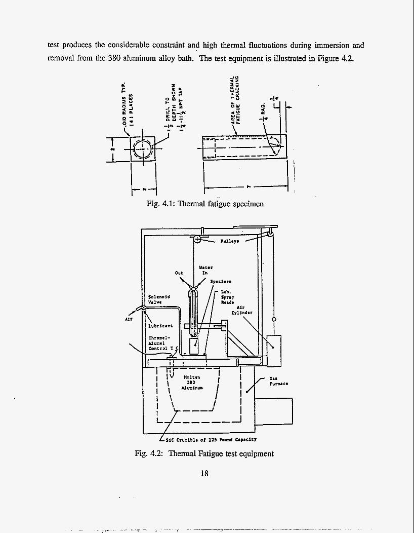
test produces the considerable constraint and high thermal fluctuations during immersion and removal from the 380 aluminum alloy bath. The test equipment is illustrated in Figure 4.2.
Air
Fig. 4.1: Thermal fatigue specimen
Fig. 4.2: Thermal Fatigue test equipment
18

The four corners have a 0.010 inch radius that intensifies the predominately uniaxial stress
at this location. The outer surface of the specimen is sprayed with a commercial water-base die lubricant just before it enters the molten aluminum bath. Water flows through the specimen at a rate of 1.5 gallon per minute. The molten bath is maintained at 1350°F and the specimen is immersed for 12 seconds and then removed from the bath for 22 seconds to produce thermal fluctuations. Typical thermal cycle at the corner surface of the specimen is shown in Figure 4.3(13). The standard procedure is to operate the test for 5,000 immersion cycles, measure the cracking pattern and follow this method for 10,000 and 15,000 total cycles. A section 3 inches long on the corners equidistant from each end on the corners was used to measure the cracks at lOOX and recorded in 100 micron ranges for depth. The cracking pattern is characterized as the average maximum crack length and the summation of the squares of the crack length for the four corners named as total crack area. The more severe the crack pattern, the lower the thermal fatigue resistance of the tested material. The results of this test have correlated closely with the behavior of dies in industry(4).
1200
1000
LL 800 0
W PI a
a W n z W
I- 400
600
200
0 0 10 20 30 40 50 60 70
TIME, SEC.
Fig. 4.3: Temperature profiles at internal and external specimen boundaries
19

5. RESULTS AND DISCUSSION
5.1 SELECTION OF THE DIE STEELS
The composition of the steels evaluated in the study is shown in Figure 5.1.1. Initially, only two steels were included in the proposal, KDA-1 and H-13. These steels were received from two sources:
a. Alloy Tool Steels of Santa Fe Springs, CA donated the KDA-1, a tool steel manufactured by Nippon Koshuha Steel in Japan. This steel is claimed to provide superior life time in Japanese die casting plants.
b. Premium Grade H-13 was donated by Latrobe Steel.
The third and fourth steels was later added to the experimental program. Per the recommendation of the Industrial Monitoring Committee a Latrobe Chromo-N steel and an Uddeholm QRO-90 were selected.
The considerations for the selection of these steels are outlined in section 3.1. Essentially, modern steel making technology in the 90’s has the potential of offering die steels that can outperform the more traditional steels. Modern steel processing methods are capable of producing cleaner steels, with less inclusions and low levels of undesirable elements such as phosphorus and sulphur. Finer and more uniform steels with identical properties in all directions and very fine microstructures are feasible. Indeed, reports of superior performance were received from die casters and squeeze casters in Europe and Asia. The squeeze casting process is a relatively new development in large scale production of aluminum components. It is more demanding on the die steel than the conventional pressure die casting. The molten and solidifying alloy, particularly in chunky castings, is kept in closer contact with the die face for longer periods of time. It heats the die face to higher temperatures, and shortens die life by producing more severe thermal fatigue cracking. This new development has accelerated the studies to obtain die steels that are more resistant.
20
New type of steels that are reported to have provided improved die life of 50% over H13 steel in equivalent casting operations has been brought to the attention of CWRU by both Japanese and German sources. It is claimed that these steels whose composition varies to some extent, have significantly extended the life of squeeze casting dies. The steels have more resistance to temperability and higher high temperature strength than that of H13. They are all produced to carbide, microstructural, sulfur and phosphorus levels and inclusion limitations that parallel those of premium grade H13. While the chemical analysis of these steels varies somewhat from one source to another, it is reported to be lower in silicon and vanadium and higher in molybdenum than conventional H13 steel. These steels are heat treated in a similar manner as premium grade H13: rapid cooling from high austenitizing temperature, double or triple tempering and avoiding surface damage during processing. The reported properties are superior to those of H13 steel. Data on the resistance to tempering, particularly with high austenitizing temperatures of 1900'F are significantly higher than those for H13 steel. The resistance to tempering is a very important consideration in resistance to thermal fatigue cracking. The surface of H13 dies that have suffered severe thermal fatigue cracking have always been softened into the low 30 Rockwell C hardness range by this tempering action.
21
22 .

5.2 OPTIMIZATION OF HEAT TREATMENT
The steels were received as-annealed. In this condition, the carbides are spheroidal as depicted in Figure 5.2.1 (a)-(c). Microscopical studies of the steels in the annealed condition have been conducted. The long term objective is to identify properties-structure relationships. One of the features monitored in this study is banding. Caused by segregation of elements during the solidification of the steel, banding can be detrimental to the properties if present in excessive amounts. Modem steel making includes elaborate procedures to eliminate this segregation. Minor differences in banding present in the steels has been detected as shown in figure 5.2.2 (a)-(c). A correlation with properties will be attempted after more data are available.
The first step was to optimize the austenitizing temperature of the steels. This work was performed in-house, utilizing a protective atmosphere tube furnace for the heating and an oil bath for the quenching. The austenitizing temperature were:
(a) 1850°F (b) 1900°F (c) 1950°F (d) 2000°F (e) 2100°F
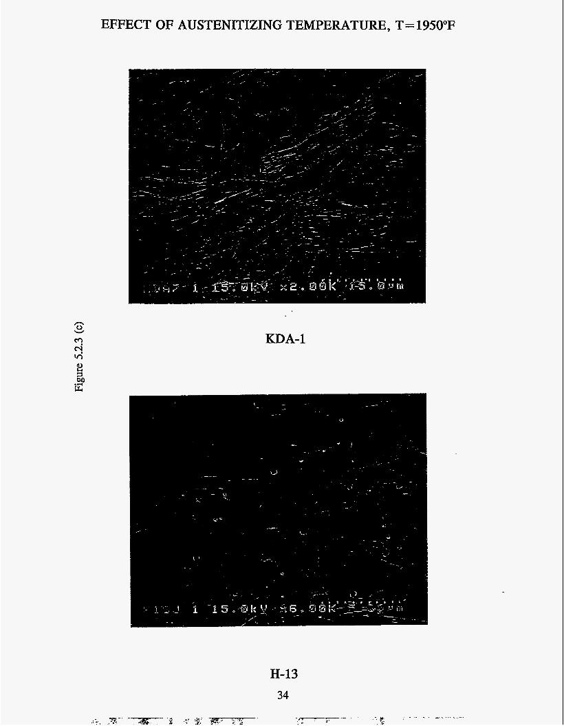
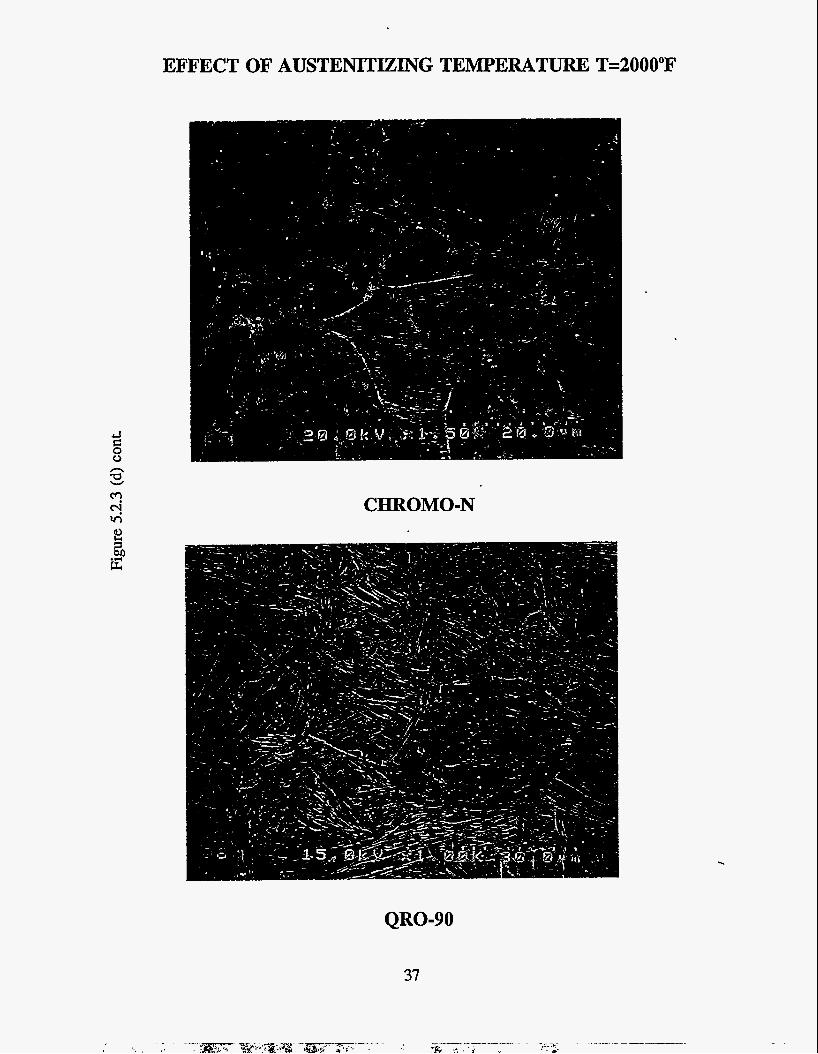
Subsequent to this controlled quenching, the hardness of each sample was measured. The samples were polished and studied by Scanning Electron Microscopy to determine the size of the grains and the solutioning of the carbides. The resulting microstructures for each one of the austenitizing temperatures are shown for each steel in Figures 5.2.3. The most obvious feature in the micrographs are the carbides. After austenitizing at 1875"F, H-13 still shows a lot of undissolved carbides while KDA-1 only has a few left. Chromo-N and QRO-90 are in-between. After austenitizing at 1900"F, H- 13 still has quite a few undissolved carbides while KDA-1 has very few left. Austenitizing at 1950°F or above leaves practically no carbides in KDA-1. Austenitizing at 2000°F eliminates the carbides from all the steels. This difference in the behavior of the steels can be attributed the lower alloying content of KDA-1, in particular the carbide forming vanadium.
23
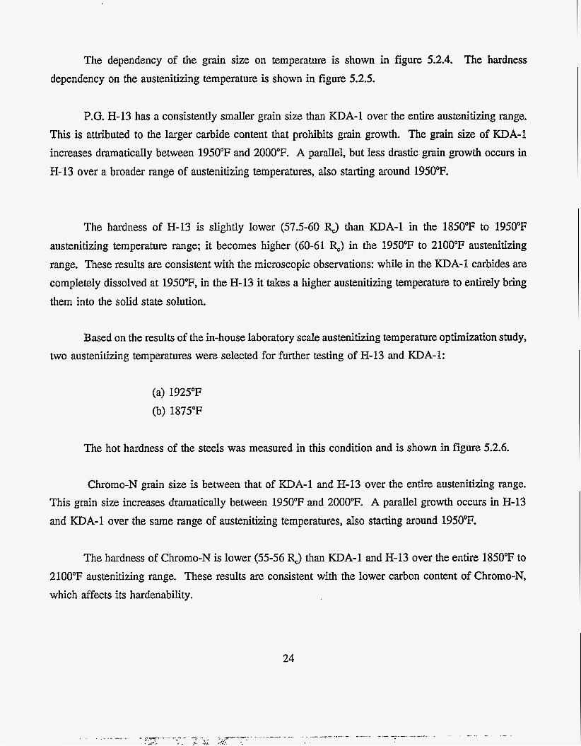
The dependency of the grain size on temperature is shown in figure 5.2.4. The hardness dependency on the austenitizing temperature is shown in figure 5.2.5.
P.G. H-13 has a consistently smaller grain size than KDA-1 over the entire austenitizing range. This is attributed to the larger carbide content that prohibits grain growth. The grain size of KDA-1 increases dramatically between 1950°F and 2000°F. A parallel, but less drastic grain growth occurs in H-13 over a broader range of austenitizing temperatures, also starting around 1950°F.
The hardness of H-13 is slightly lower (57.5-60 R3 than KDA-1 in the 1850°F to 1950°F austenitizing temperature range; it becomes higher (60-61 RJ in the 1950°F to 2100°F austenitizing range. These results are consistent with the microscopic observations: while in the KDA-1 carbides are completely dissolved at 1950"F, in the H-13 it takes a higher austenitizing temperature to entirely bring them into the solid state solution.
Based on the results of the in-house laboratory scale austenitizing temperature optimization study, two austenitizing temperatures were selected for further testing of H-13 and KDA-1:
(a) 1925°F (b) 1875°F
The hot hardness of the steels was measured in this condition and is shown in figure 5.2.6.
Chromo-N grain size is between that of KDA-1 and H-13 over the entire austenitizing range. This grain size increases dramatically between 1950°F and 2000°F. A parallel growth occurs in H-13 and KDA-1 over the same range of austenitizing temperatures, also starting around 1950°F.
The hardness of Chromo-N is lower (55-56 RJ than KDA-1 and H-13 over the entire 1850°F to 2100°F austenitizing range. These results are consistent with the lower carbon content of Chromo-N, which affects its hardenability.
24

An additional detailed study was conducted to optimize the tempering conditions. Quenched samples of Chromo-N were held for one hour at the following temperatures:
(a) 400°F (b) 600°F (c) 800°F (d) 900°F (e) 950°F (f) 1000°F (8) 1050°F (h) 1100°F (1) 1200°F
The hardness was then plotted as a function of this tempering temperature as shown in Figure 5.2.7. The results of this study indicate a steep loss in hardness beyond 950°F. Tempering Chromo-N for one hour at 1100°F results in a drop from 55-56Rc (as-quenched hardness) to 42Rc. This hardness is less than desirable for a die casting die. It may also pose a practical difficulty for the heat treaters of die materials, since it behooves separate heat treatment. Tempering Chromo-N along with H-13 at 1100°F would result in unacceptably low hardness levels. The optimized tempering includes 1 hour (21040°F followed by a second 1-2 hours temper at 1000°F.
The fourth steel added to the benchmarking study in coordination with our Industrial Monitoring Committee, QRO-90, is made by Uddeholm who claims better performance than Premium Grade H-13. This steel is more temper resistant, as indicated by the smaller drop in hardness at the higher austenitizing temperatures.
25

ANNEALED CARBIDE STRUCTURE
Figure 5.2.1 (a) H-13 8OOX Nital Etched
Figure 5.2.1 (b) WA-1 8OOX Nital Etched
26

ANNEALED CARBIDE STRUCTURE
27
.

BANDING
Figure 5.2.2 (a) HI3 Premium Grade 50X Nital Etch
4
Figure 5.2.2 (b) KDA-1 50X Nit4 Etch
28
. ~. .. ---- ~ - - - ~ , ~ -.e---- --
A . . . !., .; .. -... .. ~ ~ , ~ - - .. .,, ~ - -- 4

BANDING
Figure 5.2.2 (c) QRO-90 50X Nital Etch
29
.

EFFECT OF AUSTENITIZING TEMPERATURE, T= 1850°F
n cd W
KDA-1
.
H-13 30

EFFECT OF AUSTENITIZING TEMPERATURE T=185OoF
3 c 0 0
CHROMO-N
QRO-90
31

"! Y v,
EFFECT OF AUSTENITIZING TEMPERATURE, T = 1900°F
H-13
32
KDA-1

EFFECT OF AUSTENITIZING TEMPERATURE T=1900°F
CHROMO-N
QRO-90
33
EFFECT OF AUSTENITIZING TEMPERATURE, T= 1950°F
n 0 v
r? x KDA-1
H-13 34

EFFECT OF AUSTENITIZING TEMPERATURE T=l95O0F
CHROMO-N
QRO-90
35

"! x M iz
EFFECT OF AUSTENITIZING TEMPERATURE, T =2000°F
KDA-1
.-
Y
.
H-13
36
EFFECT OF AUSTENITIZING TEMPERATURE T=2000°F
CHROMO-N
QRO-90
37
.

EFFECT OF AUSTENITIZING TEMPERATURE, T=2100°F
KDA-1
H-13 38

CHROMO-N
QRO-90
39

.b 0
Figure 5.2.4
GRAIN SIZE vs AUSTENlTlZlNG TEMPERATURE
1850 1900 1950 2000 2050 Austenitizing Temperature (OF)
2100

Figure 5.2.5
HARDNESS AFTER QUENCH i I i i i ......... I
I
.....-.-.-. + -.--.-.-.-..............._._._. J ...........-.-.-.-.-..........._._._._., A
i i Y
i I
................. 4 i ......................................... * i ...................................... i i i i ............ ......................................... ”.“t””’......-.-.-.-.-............_._._.I.. i i i i i ........... 1 ......................................... 4 ...........-.-.-.-.-............I._.I._..
..._._._._..,
4
................. .......................................... !
i i
...... ................................ - -.-.- ‘-.“........“.-1-.-.--
.......... .......................................... .. ................................... -O- CHR-N
I I
i 4 .............................. .& i ._-........_._._._.......,....._.
50 1
i i i i 48 --.-.-. I f
i
i 46
1850 1900 1950 2000 2050 Austenitizing Temperature (OF)
21 00

I 8
F
f U (d
z a r i : s I S 0 0
i i i i
8 v) cv
42
8 m l-
l-
l-

HARDNESS AT ELEVATED TEMPERATURE
-
Figure 5.2.7 700 a
.............. ....... ...... ...................... ............................ ................................ ....................... ........................ --.*--..- i -..! g ......; : i ..:.. - , . - -
........................... ................................ -.. ............................................................................ ............... 9.: .-..: ~ ......................... - . .
- - - e . .......................... ..(.. ............................................................ ..:.. ......................................................... ,.: .......................... B -
- - e . . . . . . . . . . . . . . . . . . . . . . . . . . . : . . . . . . . . . . . . . . . . . . . . . . . . . . . . . . . . . . . . . . . . . . . . . . . . . . . . . . . . . . . . . . . . . . .
I I I I t I I I I I I t I I I Q I , I I I
B I
I I I
600
500
8 . . . . . . . . . .
.............
......
. . . . .
400
300
200
100
0
. . . ....
..... . . . . .
z
.............................................
..................................................
o KDA-1850 KDA-1950
A HI 3-1 850 X Hl3-1950 . . . . . . . . . . . . . . . . . .
200 400 600 800 1000 1200 1400
Temperature (OF)
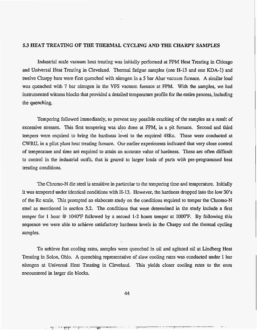
5.3 HEAT TREATING OF THE THERMAL CYCLING AND THE CHARPY SAMPLES
Industrial scale vacuum heat treating was initially performed at FPM Heat Treating in Chicago and Universal Heat Treating in Cleveland. Thermal fatigue samples (one H-13 and one KDA-1) and twelve Charpy bars were first quenched with nitrogen in a 5 bar Abar vacuum furnace. A similar load was quenched with 7 bar nitrogen in the VFS vacuum furnace at FPM. With the samples, we had instrumented witness blocks that provided a detailed temperature profile for the entire process, including the quenching.
Tempering followed immediately, to prevent any possible cracking of the samples as a result of excessive stresses. This first tempering was also done at FPM, in a pit furnace. Second and third tempers were required to bring the hardness level to the required 48Rc. These were conducted at CWRU, in a pilot plant heat treating furnace. Our earlier experiments indicated that very close control of temperature and time are required to attain an accurate value of hardness. These are often difficult to control in the industrial outfit, that is geared to larger loads of parts with pre-programmed heat treating conditions.
The Chromo-N die steel is sensitive in particular to the tempering time and temperature. Initially it was tempered under identical conditions with H-13. However, the hardness dropped into the low 30’s of the Rc scale. This prompted an elaborate study on the conditions required to temper the Chromo-N steel as mentioned in section 5.2. The conditions that were determined in the study include a first temper for 1 hour @ 1040°F followed by a second 1-2 hours temper at 1000°F. By following this sequence we were able to achieve satisfactory hardness levels in the Charpy and the thermal cycling samples.
To achieve fast cooling rates, samples were quenched in oil and agitated oil at Lindberg Heat Treating in Solon, Ohio. A quenching representative of slow cooling rates was conducted under 1 bar nitrogen at Universal Heat Treating in Cleveland. This yields closer cooling rates to the ones encountered in larger die blocks.
44

In conclusion, heat treating of the samples has been completed under three cooling conditions:
1. Fast quench using an oil quench at Lindberg Heat Treating in Solon, Ohio.
2. Medium quench using 5 bar, 7 and 10 bar nitrogen gas cooling at FPM Heat Treating in Chicago.
3. Slow quench using a 1 bar nitrogen cooling at Universal Heat Treating in Cleveland, Ohio.
All the heat treatments were provided as in-kind contributions to the project.
The cooling rates were recorded by thermocouples embedded in witness blocks. Figure 5.3.1 shows typical cooling rates of a thermocouple embedded in a 2"x2"x3.8" block, one inch below the center of the 2"x2" side. Figure 5.3.2 shows cooling curves measured by a thermocouple embedded inside the wall of a thermal cycling sample, 3 inches below the top, halfway between the corner and the bore. A summary of the cooling conditions is shown in figure 5.3.3.
5.4 CHARPY V-NOTCH IMPACT TESTING OF THE STEELS
All the steels in the study were subjected to the Charpy V-notch impact test to evaluate their toughness. The NADCA Die Materials Committee also suggested that brittle-ductile transition temperature is determined. In order to do so, the test was conducted at: -100"F, 80"F, 220"F, 300°F and 475°F. The results for each steel are plotted in figures 5.4.1 to 5.4.4.
The data confirms the significant increase in toughness with temperature for all the steels. It also indicates higher toughness for steels that were quenched in oil, i.e. fastest quenching rates. This trend overlaps the increased toughness associated with lower hardness. Further work is underway to separate between these two variables and determine their relative contribution.
45

Figure 5.3.1
.:i
Cooling Curves for Thermal Cycling and Charpy-V Notch Samples
2000.00 3
1500.00 rn
O W
k
0
2 4 1000.00 d k 0
l? 0
€+ 500.00
0.00 0
Average Cooling Rates (1750°F - 550'F) 0 il - 342"F/min IO bar Nz - 2OO0F/min 7.5 bar N2 - 207"F/min 5 bar N2 - 162 "F/min
5 bar NZ
7.5 bar N2 lobar N 2

0 0 0 0 0 0 0 0 0 0 0 0 0 0 0 0 00 <o d 0 00 (D d P
cy r P P r
n 0 Q, u) U
w E
(do) 3UnlW3dUU31
47

I
Fas t(<342"F/min) oil quenching
Medium(<l6O0F/min)
Slow (>8 O"F/min)
Figure 5.3.3
Heat Treating of Thermal Cycling and Charpy V-notch Samples
H-13 KDA-1 CHROMO-N QRO-90
From 1875°F From 1875°F From 1875°F From 1875°F From 1925°F . From 1925°F
From 1875°F From 1875°F From 1875°F From 1875°F Sbar, 7.5bar Sbar, 7.5bar lobar lobar
From 1875°F From 1875°F From 1875°F From 1875°F lbar lbar lbar lbar

!
!
Figure 5.4.1
CHARPY IMPACT PROPERTY OF HI3
40
-A- H-13, 19250iVRc47 35
-X- H-13, 1875vac7bar/Rc50 30 4-1
-0- H- 13,1875vac5bar/Rc50 i i
25
20
15
10
5 -1 00 0 100 200
Temperrature (OF) 300 400

cn 0
Figure 5.4.2
CHARPY IMPACT PROPERTY OF KDA-1
t I I i 40
25
20
15
I O
5 -1 00
t
+ KDA-1, 1875Olt/RC46
-0- KDA-1 1925Oil/Rc45
-&- KDA-1 1875vac7bar/Rc48
--Jt KDA-1 1875vac5bar/Rc49
0 100 200
Temperature (OF)
............ ..... +
- ,.............. ...
...... ...-.-....
300 400

c U w e 0 U e 0
v)
2 m P 0 o m > v) b co
E
l-
0- c? 0 U a
t
3 0 d 0
F v) 0
51
0

cn N
Figure 5.4.4
CHARPY IMPACT PROPERTY OF CHROMO-N
40
35
30
s U 2 25
P h
g 20 u1 0 x 15 E
10
4.4
-
5
0
i i i i
t i I I
i 1
I i ...... ..- + CHR-N, 1875oiVRc46
..... "... --E CHR-N, 1875vacl ObaVRc46.5 i
....... i...... ............... ̂.̂._.I ............_.... "i ................ I ....................... .̂... "."i ........... " ........ 1
i i i
i i i i
I
I f 1
i i ....... ..I... ............... " .... -.- ............-. - .... ~ ........................................................................
i i I
I I
I I
I 1
-1 00 0 100 200 300 400
Temperature (OF)

5.5 THERMAL CYCLING EVALUATION OF THE STEELS
H-13 was first to be tested. The main reason for this choice is to ensure a common base-line of the results with earlier thermal cycling testing. This is a time consuming, elaborate test and we wanted to make sure that the results can be correlated to previous studies at CWRU on the same testing unit. The results of the current test are indeed in the same range thus facilitating comparisons with our earlier data for interpretation purposes.
Another test was conducted with two thermocouples embedded in the thermal fatigue sample. These were connected to a data acquisition system, and recorded the temperature fluctuations over the entire duration of the test. Such data are necessary to confirm the temperature ranges experienced by the sample, before this comprehensive thermal fatigue testing program.
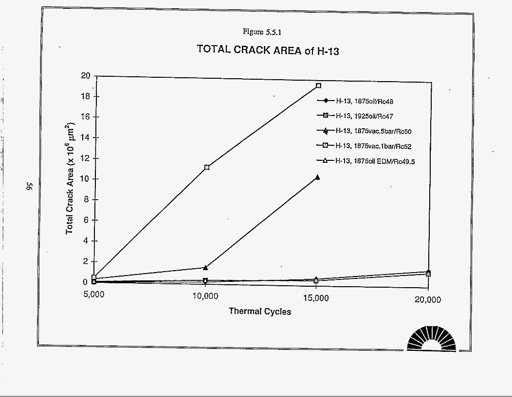
The results of the thermal cycling testing for H-13 are shown in figures 5.5.1 and 5.5.2 as Total Crack Area and Average Maximum Crack Length respectively. Based on many years of testing materials for Thermal Fatigue, these have been identified as the best predictors of resistance to thermal cycling. The heat treating conditions and as-tempered hardness are labeled for each curve The curves demonstrate increasing resistance to thermal fatigue with faster cooling rates. Notice that larger values i.e. the upper curves, are indicative with a larger area of cracks or longer cracks. The higher a curve is on the plot, the worse its relative thermal fatigue resistance. The tempered hardness of the evaluated samples was in the range of 47-52 Rc. In this range the samples with a higher tempered hardness showed less resistance to thermal cycling than the samples that were tempered to a lower hardness level. Further evaluation is underway to clarify the relative significance of this finding.
Figures 5.5.3 and 5.5.4 are composite plots for all the samples tested so far in the program. Over the first 10,000 cycles the Chromo-N sample developed only a few fine thermal fatigue cracks; however, it also spalled locally on the hottest (bottom) end, which is a concern. After the sample completed the 10,000 cycle it was removed for crack evaluation. It was then returned to the testing unit
53

for the next 5,000 cycle. Before the test was started, we noticed gross cracking on the side of the sample as shown in figure 5.5.5. The crack started at the top end, near the threads and propagated along the side of the sample with some branching. Tightening the sample holder screw onto the thread induces tensile stresses in this area. Coupled with the cold cooling water, these stresses were sufficient to cause gross cracking. As pointed out earlier, the Chromo-N die steel is more sensitive to the tempering time and temperature than the other steels. In the first heat treating cycle, it was tempered under identical conditions with H-13. However, the hardness dropped into the low 30's on the Rc scale. The heat treating conditions were customized to include a first temper for 1 hour at 1040°F followed by a second 1-2 hours temper at 1000°F. By following this sequence we were able to achieve satisfactory hardness levels of 46-47Rc in the Charpy and the thermal cycling samples. The tendency to soften could also affects the heat checking during the thermal cycling test. It was noticed that the hardness of the thermal cycling sample dropped gradually from the "as heat treated" 46-47 Rc to the middle 30's. Overall, the performance of Chromo-N under the thermal cycling conditions of our test was relatively poorer than the other steels.
The QRO-90 samples show better resistance to thermal cycling as demonstrated by the curves in figures 5.5.3 and 5.5.4. However, gross cracking was encountered with one of these samples. This catastrophic failure was attributed to a local defect in this particular steel batch. Testing of all samples made of this batch was put on hold, since catastrophic failures could cause damage to the equipment.
Extensive thermal cycling of the KDA-1 steel was conducted over this reporting period. The testing included oil quenched samples cooled at a fast rate (over 342"F/min) as well as a vacuum quenched samples cooled at a medium cooling rate (over 160"F/min) and vacuum quenched samples cooled at a slow cooling rate (under 80"F/min). The results are plotted along with the other steels in figures 5.5.3 and 5.5.4; also separately in figures 5.5.6 and 5.5.7.
The results clearly demonstrate that the thermal fatigue resistance of KDA-1 is superior to Premium Grade €3-13. We regard this as a major milestone in the project, and an important breakthrough in the die materials research. The superior performance is attributed to the lower silicon and vanadium present in this steel.
*
The oil quenched sample did not develop any thermal fatigue cracks after 15,000 cycles. Testing
54
. _ . . .- . a-
A .
. - I...- _ _ . .. --._ . .-
I .- .. . , .
ir l* - *I - r r

was extended to 20,000 and then to 25,000 cycles. This extension goes well beyond the normal 15,000 thousand cycles, yet did not generate any thermal fatigue cracks on the four corners of the thermal fatigue sample. The vacuum quenched sample showed practically no cracks after 15,000; the test was extended to 20,000 and even then only few very small cracks could be detected.
It is important to put these results in a perspective: thermal fatigue resistance is strongly related to life time of the die. A higher thermal resistance means longer die life with all the economical implication associated with it. The CWRU accelerated thermal fatigue test developed by one of the authors (J.F. Wallace) forty years ago has gained international acceptance as a good indicator of die steel behavior in die casting operations. This benchmarking study was initiated with the premise that modem 90’s steel making technology may be able to produce hot die steels that are superior to the Premium Grade H-13 commonly used in the US. The results of the thermal cycling test demonstrate this to be true.
The word on the superior thermal fatigue resistance of KDA-1 demonstrated by our study is spreading in the die casting community. It is considered by many as a major milestone and an important breakthrough in the die materials research.
55
i
I
I - 1 I
Figure 5.5.1
TOTAL CRACK AREA Of H-13
20
18 -+- H-13, 1875oil/Rc48
H-13, 1925oil/Rc47 16 -8- H-13, 1875vac,5bar/Rc50
-P- H- 13, 1875vac. 1 bar/Rc52 14
12 *H-l3, 1875oil EDM/Rc49.5
10
8
6
4
2
0 10,000 15,000 20,000
Thermal Cycles

I
Figure 5.5.2
AVERAGE MAXIMUM C R A C K LENGTH Of H-13
0 -( 1
5,000 I0,OOO 15,000 Thermal Cycles
20,000

. -.-
Figure 5.5.3
TOTAL CRACK AREA
20
18
16
14
12
10
8
6
4
2
0
-+- H-13, 1875oil/Rc48 +H-13, 1925oiI/Rc47 -A- H- 13, 1875vac.5bar/Rc50 -f3- H- 13, 1875vac. 1 bar/Rc52
++- KDA- 1, 18750il/Rc46 -Nk- KDA-1, 19250il/Rc45 4 KDA-1 , 1875vac.7bar/Rc49 U KDA-1 , 1875vac. 1 bar/Rc50
4- QRO-90, 1875vac. 1 Obar/RcS 1 -.IC QRO-90, 1875vac. 1 bar/Rc50 4 CHR-N, 18750il/Rc47
. . . ...: .’.. .. . . . . H-13, 1875oil EDM/Rc49.5
....$* ”*’ KDA-1, 1875oil EDWRc49
IC49
I
15,000 20,000 5,000 10,000
Thermal Cycles

Figure 5.5.4
AVERAGE MAXIMUM CRACK LENGTH +H-13, 1875oil/Rc48 -@-H-13, 1925oil/Rc47 - 4 ~ H-13, 1875vac,5bar/Rc50 -0- H- 13, 1875vac. 1 bar/Rc52 -b-H-13, 1875oil EDM/Rc49.5 ++ KDA- 1, 18750iVRc46 -46- KDA-1 , 1925oil/Rc45 -4- KDA-1 , 1875vac.7bar/Rc49 -3e- KDA- 1 , 1875vac. 1 bar/Rc50 -3%- KDA- 1 , 1875oil EDWRc49 -t- QRO-90, 1875vac. 10bar/RcS 1 -c- QRO-90, 1875vac. 1 bar/RcSO 4 C H R - N , 1875oil/Rc47 4 CHR-N, 1875vac.lObar/Rc46.5 -0- CHR-N, 1875vac.l bar/Rc49
Thermal Cycles

60

II a I- O f-
?
- .- 0 10 h 2
0 0
0 0-
Y
I
61

Figure 5.5.7
AVERAGE MAXIMUM CRACK LENGTH of KDAl .
4
n
E 3.
s 3 P X .c c3) c a, J
v
+-,
r 2 t 2
k
m
x
L m % I a,
0
-4- KDA-1, 1875oil/Rc46
+&- KDA- 1, 1925oillRc45
4 KDA-1 1875vac.7bar/Rc49
4+ KDA- 1, 1875vac. 1 badRc50
-?&-KDA-l, 1875oil EDMRc49
ut m W
m 1 5,000 10,000 15,000
Thermal Cycles 20,000

5.6 EFFECT OF EDM
1. Three samples were quenched in oil at Lindberg Heat Treatment: H-13, KDA-1 and QRO-90. The cooling curve were recorded by a thermocouple embedded in the center of one of the samples. The samples were then double tempered at 1100°C. This heat treatment was provided by Lindberg Heat Treatment as an in-kind contribution to the project.
2. The three samples were taken to DCD Technologies for Electro Discharge Machining. Dr. Walter Smith, the President of the company suggested a build-in control that would provide a base line for the evaluation of the EDM effect. To this end, we would process h e comers by EDM while the fourth one is ground.
3. After the three corners were processed by EDM, the samples were tempered to alleviate the impact of the EDM. They were subsequently polished at Sun Polishing Corp. to remove the topmost white layer.
The procedures followed in the preparation of these samples closely follow the die finishing operation. It is therefore reasonable to expect those to simulate the behavior of real dies. All the processing work, including EDM at DCD Technologies, heat treating and polishing at Sun Polishing Corp. were provided as an in-kind contribution to the project. The samples are being currently tested. Results will become available during the second year of the project.
5.7 IN-PLANT EVALUATION
Along with the continuation of the in-house testing program, we are planing the details of the in-plant evaluation. The in-plant part of the evaluation has to be conducted in a production environment. It is realized that under production conditions, we need to be sensitive to the schedules and constrains of the plant, and so the plans have to be mutually agreeable.
Progress was made in the planning on the in-plant testing. After preliminary discussions with
63

Mr. Jim Knirsch, Technical Director of I" Automotive in Solon, Ohio a meeting took place. Mr. Thomas Bandwen is the coordinator for the in-plant testing. At the meeting, a die insert was selected for the testing. The part is an Ejector Center Insert. It is used in making a cover for a transmission. The die has four identical die cavities with these inserts. The inserts are notorious for their short life time. Based on our recommendations, inserts will be made of KDA-1 and Premium Grade H-13. We will supervise the heat treating. The inserts will be put in use and their performance monitored. The in-plant testing will proceed slowly and be driven by production schedules. Understandably, we have less control over the schedule.
6. SUMMARY AND INTERIM CONCLUSIONS
The results of the thermal cycling evaluation demonstrate that the thermal fatigue resistance of KDA-1 is superior to Premium Grade H-13. We regard this as a major accomplishment in the project, and an important breakthrough in the die materials research. The superior performance is attributed to the lower silicon and vanadium present in this steel.
The oil quenched KDA-1 samples did not develop any thermal fatigue cracks after 15,000 cycles. Testing was extended to 20,000 and then to 25,000 cycles. This extension goes well beyond the normal 15,000 thousand cycles, yet did not generate any thermal fatigue cracks on the four corners of the thermal fatigue sample. The vacuum quenched sample showed practically no cracks after 15,000; the test was extended to 20,000 and even then only few very small cracks could be detected.
It is important to put these results in a perspective: thermal fatigue resistance is strongly related to life time of the die. A higher thermal resistance means longer die life with all the economical implication associated with it. The CWRU accelerated thermal fatigue test developed by one of the authors (J.F. Wallace) forty years ago has gained international acceptance as a good indicator of die steel behavior in die casting operations. This benchmarking study was initiated with the premise that modern 90's steel making technology may be able to produce hot die steels that are superior to the Premium Grade H-13 commonly used in the US. The results of the thermal cycling test demonstrate this to be true.
64

The thermal cycling resistance of QRO-90 was between Premium Grade H-13 and KDA-1 for the sample quenched at 10 bar nitrogen. The testing of this steel was interrupted after one of the samples failed by gross cracking. Chromo-N had the lowest thermal fatigue resistance of all steels tested in this program. The testing of Chromo-N was also interrupted after one of the samples failed by gross cracking.
The results of the thermal cycling evaluation demonstrate increasing resistance to thermal fatigue with faster cooling rates.
The Charpy-V notch results confirm a significant increase in toughness with temperature for all the steels. Also, higher toughness for steels that were quenched in oil, i.e. fastest quenching rates. This trend overlaps the increased toughness associated with lower hardness in the as-tempered condition. Further work is underway to separate between these two variables and determine their relative contribution.
7. FUTURE WORK
The project has been making excellent progress. Two steels have been added to the original research plan, at the recommendation of the NADCA Die Materials Committee. Despite this expansion in the extent of the experimental program, the project is ahead of the original schedule.
Currently, the focus is on the effect of the EDM process on the thermal fatigue resistance. At the same time, steps have been taken to proceed with the in-plant evaluation of the steels.
Along with the continuation of the in-house testing program, we are planing the details of the in-plant evaluation. The in-plant part of the evaluation has to be conducted in a production environment. It is realized that under production conditions, we need to be sensitive to the schedules and constrains of the plant, and so the plans have to be mutually agreeable. The objective is to identify demanding die casting applications that have traditionally required frequent die components replacements as a result of premature failure. Replacement die components will be fabricated using the improved steel. These die components will be put in service, and their performance compared with the conventional steel die.
65

Based on previous reports of die failures, it is known that certain slides are prone to failure. These slides are the main candidates for our testing and evaluation. Additional critical components have been identified. The performance of the conventional components will be monitored and recorded, including operational parameters such as die pre-heating temperature, lubrication, metal temperature and cooling procedures. Identical components will be fabricated by our industrial sponsors as an in-kind contribution to the program using the new steel. These components will be put in use, preferably under the same operational conditions Le. same die pre-heating temperature, lubrication, metal temperature and cooling procedures. The performance of these components will be monitored and recorded.
8. REFERENCES
1. Anon.'Technology Transfer, R&D will enhance die casting competitiveness', Modem Metals, Vol. 50, Dec., 1994, pp. 16
2. P.C. Mukherjee, 'Fundamentals of Metal Casting Technology', 2nd Edition, Oxford & IBH
Publishing Co. PVT. LTD., 1988, pp. 29-89.
3. A.C. Street, 'The Diecasting Book', Portcullis Press Ltd., 1977, pp. 3-7, 349-351.
4. D.L. Cocks, 'Increasing Die Life', Transaction of the 14th International Pressure Casting Conference,
Solihull, UK, May 1993, pp. 17/1-17/23.
5. C.Y. Nieh, 'Thermal Fatigue Behavior of H-13 Die Steel for Aluminum Die Casting with Various Ion Sputtered Coatings', Master Thesis, CWRU, 1981.
6. Y. Birol, 'Reduction in Corrosion in Aluminum Die Casting Dies', Master Thesis, CWRU, 1984. 7. R. Shivpuri, M. Yu & K. Venkatesan, 'A study of erosion in die casting dies by multiple pin
accelerated erosion test', Journal of Materials Engineering and Performance, Vol. 4, April, 1995, pp.
145- 153. 8. R.B. Bertolo, 'Fracture Toughness of Aluminum Die Casting Die Steels', Ph.D. Thesis, CWRU,
1976.
9. W. Young, 'Why Die Casting Dies Fail', Transaction of the 10th International Die Casting Congress,
pp. G-T79-092, 1979. 10. W. Young, 'Die Casting Die Failure and Its Prevention'. Precision Metal, Vol. 37, 1979, pp. 28-31.
66

11.
12.
13.
14.
15. 16.
17.
18. 19.
20.
21.
22.
23.
24.
25.
B.J. Barrow, 'The Effect of Selected Surface Treatment, Various Welding Procedures, and Stress
Relieving on the Thermal Fatigue Resistance of H-13 Die Steel for Aluminum Die Casting Dies',
Master Thesis, CWRU, 1982. S.J. Noesen & H.A. Williams, 'The Thermal Fatigue of Die Casting Dies', 4th National Die
Casting Exposition and Congress, Paper No. 801, 1966.
J.C. Benedyck, D.J. Moracz & J.F. Wallace. ' Thermal Fatigue Behavior of Die Materials For Aluminum Die Casting', 6th SDCE International Die Casting Congress, Paper No. 111,1970.
K. Venkatesan & R. Shivpuri, 'Experimental and Numerical Investigation of the Effect of
Process Parameters on the Erosive Wear of Die casting Dies', Journal of Materials Engineering
and Performance, Vol. 4, April, 1995, pp. 166-174.
Anon. ' Preventing Failure in Die Casting Dies', Precision Metal, Vol. 39, 1981, pp. 102-110.
S . Malm & J. Tidlund, 'Increased Life for Die Casting Dies', Transactions of the 10th International Die Casting Congress, Paper No. IG-T79-051, 1979.
R.R. Graham, 'Thermal Processing, Structure and Thermal Fatigue Relations for Die Steel',
Master Thesis, CWRU, 1974
J.F. Wallace, 'Thermal Conditions in the Die', Foundry, Vol. 96, 1968, pp. 176-179.
G. Dieter, 'Mechanical Metallurgy', 3rd Ed., McGraw-Hill Inc., 1986, pp. 430. S.K. Das, 'Effect of Heat Treatment on the Thermal Fatigue Behavior and Fracture Toughness
of H-13 Steel for Aluminum Die Casting Dies', PbD. Thesis, CWRU, 1981. W.E. Blatz, 'Effect of Austenitizing Temperature and Time on Impact Strength of AIS1 H-13
Hot Work Steel', Allegheny Ludlun Research Center, Technical Memorandum No. 'I'M-70-286,
Nov. 9, 1970.
M.L. Schmidt, 'Effect of Austenitizing Temperature on the Structure and Mechanical Property
Behavior of Laboratory Treated Specimens and Large Section Sizes of H-13 Tool Steel', SDCE
14th International Die Casting Congress and Exposition, Paper No. G-T87-006, 1987.
R.R. Graham, 'Thermal Fatigue Mechanisms in Aluminum Die Casting Die Steels', Ph.D. Thesis,
CWRU, 1978. A. Kasak & G. Steven, 'Microstructural Considerations in Heat Checking of Die Steels', 6th
International Die Casting Congress, Paper No. 112, Cleveland, Nov., 1970. H.J. Sharp, 'Aluminum Pressure Die Casting Dies-Their Failure by Surface Cracking', Metal
67

26.
27.
28.
29.
30.
31.
32.
33.
34.
35.
36.
Industry, Feb. 20, 1953, pp. 141-143.
T. Arai, 'Research and Application of Carbide and Nitride Coatings onto Aluminum Die Casting
Molds in Japan', Transactions of the 18th International Die Casting Congress and Exposition,
October, 1995, pp. 327-336.
F.R. Hochman, 'Surface Modification', Advanced Materials & Processes', Vol. 147, January,
1995, pp. 29-30.
3.F. Wallace, 'Effect of Cooling Rate during Heat treatment of the Structure and Toughness of
Premium Grade H-13 Die Steels for Aluminum Die Casting Dies', Report No. 585-21, Die
Casting Research Foundation, July, 1987. 'Chrysler Corporation Specification, NP-2080', Die Casting Engineer, September-October,
1974, pp. 35. Anon.'Hot Work Tool Steel Microstructure', Die Casting Engineer, September-October, pp. 34- 35, 1974.
C.M. Berger & J. Finn, 'The Effect of Annealed Microstructure on the Impact Toughness of
Premium H-13 Die Steel', Transactions of the 18th International Die Casting Congress and
Exposition, October, 1995, pp. 357-359. P.W. Hockanadel, G.R. Edwards, M.C. Maguire & M.D. Baldwin, 'The Effect of Microstructure on the Thermal Fatigue Resistance of Investment Cast and Wrought AIS1 H-13 Hot Work Die
Steel' Transactions of the 18th International Die Casting Congress and Exposition, October, 1995,
pp. 343-355.
B. Gehricke, B. Klarenfjord, A. Schindler & I. Schruff, 'Relation between Microstructure and
Ductility of Hot-Work Tool Steels H-11 and H-13 - Presentation of New Acceptance References
for Microstructures', Transactions of the 18th International Die Casting Congress and Exposition,
October, 1995, pp. 337-342.
M.L. Schmidt, 'What Really Influences the Mechanical Properties of Premium H-13 Tool Steel?' Transactions of the 15th International Die Casting Congress And Exposition, Paper No. G-T89-
001, October, 1989.
S. Kallpakjian, 'Manufacturing Processes for Engineering Materials', Addison-Wesley Publishing CO., 1984, pp. 1-4.
R.L. Bormann, 'Cut Surface Quality-the Pluses and Minuses of EDM', Tooling and Production,
68

37.
38.
39.
40.
41.
42.
43.
44.
45.
46.
47.
48.
January, Vol. 50, 1985. pp. 37-50.
D.G. Backman, R. Mehrabian & M.C. Flemings, 'Die Thermal Behavior in Machine Casting of Partially Solid High Temperature Alloys', Metallurgical Transactions, Vol. 8B, September, 1977,
pp. 471-477.
M.C. Flemings & K.P. Young, 'Thixo Casting of Steel', Transactions of the 9th SDCE Die
Casting Congress, 1977, Paper No. G-T77-092.
R.P. Dunn, 'Thermal Fatigue Behavior of H13 Steel and other Die Materials for Aluminum Die
Casting', Die Casting Research Foundation, 1969 Annual Meeting, Report No. 01-69-02D.
S.S. Manson, 'Thermal Fatigue of Die Casting Dies-A Review and Proposed Future Program',
Technical Report 01-72-05D, Die Casting Research Foundation.
L-A. Norstrom, B. Johansson & N. Ohrberg, 'Thermal Fatigue and Thermal Shock Behavior of Martensitic Hot Work Steel', Transactions of the 11th International Die Casting Congress and
Exposition, Paper No. G-T81-093, 1981.
K.E. Thelning, 'How Far Can H-13 Die Steel be Improved', Transactions of the 6th International '
Die casting Congress, Paper No. 114, November, 1970. R. Mehrabian, D.G. Backman, 'Casting of Partially Solid Metals and Metal-Non Metal Composites', Transactions of the 9th SDCE Die Casting Congress, Paper No. G-T77-093, 1977.
P.T. Heald, 'The Oxide Wedging of Surface Cracks' Materials Science and Engineering, Vol.
35, 1978, pp. 165-169.
L.L. Centa & J.F. Wallace, 'The Effect of Electro-Discharge Machining on the Surface and Sub- Surface Microstructure of H-13 Die Steel', Transactions of the 15th International Die Casting
Congress and Exposition, Paper No. G-T89-032, October, 1989.
C. J. Dorsch and H.P. Nichols, 'The Effects of EDM on the Surface of Hardened H-13 Die
Components', Transactions of the SDCE International Die Casting Congress, Paper No. G-T89-
031, 1989. H.J. Kim, 'The Analysis of Mitigation of the Influence of Electro-Discharge Machining on the
Thermal Fatigue Properties of H-13 Die Steel', Ph.D. Thesis, CWRU, 1991.
J.F. Wallace and W. Roberts, 'Influence of Cooling Rate on the Microstructure and Toughness
of Premium Grade H-13 Die Steels', Transactions of the 15th International Die Casting Congress
and Exposition, Paper No. G-T89-013, 1989.
69
49. D. Schwam, R.M. Aikin, Jr. & J.F. Wallace, 'Controlled Heat Treatment in Vacuum Furnace and
Distortion of Die Casting Dies of H-13 Steel', Transactions of the 18th International Die Casting
Congress and Exposition, October, 1995, pp. 319-325.
70