Embed Size (px)
Citation preview
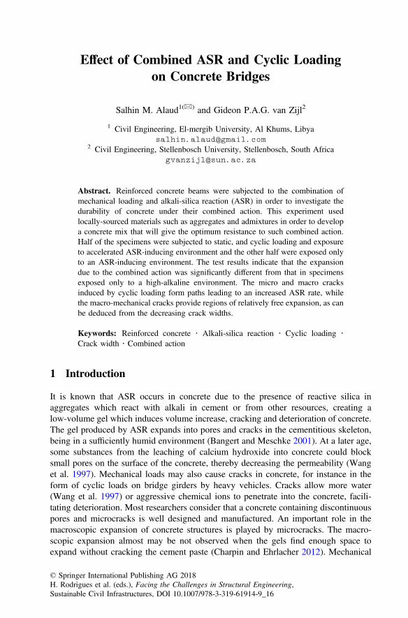
Effect of Combined ASR and Cyclic Loadingon Concrete Bridges
Salhin M. Alaud1(&) and Gideon P.A.G. van Zijl2
1 Civil Engineering, El-mergib University, Al Khums, [email protected]
2 Civil Engineering, Stellenbosch University, Stellenbosch, South [email protected]
Abstract. Reinforced concrete beams were subjected to the combination ofmechanical loading and alkali-silica reaction (ASR) in order to investigate thedurability of concrete under their combined action. This experiment usedlocally-sourced materials such as aggregates and admixtures in order to developa concrete mix that will give the optimum resistance to such combined action.Half of the specimens were subjected to static, and cyclic loading and exposureto accelerated ASR-inducing environment and the other half were exposed onlyto an ASR-inducing environment. The test results indicate that the expansiondue to the combined action was significantly different from that in specimensexposed only to a high-alkaline environment. The micro and macro cracksinduced by cyclic loading form paths leading to an increased ASR rate, whilethe macro-mechanical cracks provide regions of relatively free expansion, as canbe deduced from the decreasing crack widths.
Keywords: Reinforced concrete � Alkali-silica reaction � Cyclic loading �Crack width � Combined action
1 Introduction
It is known that ASR occurs in concrete due to the presence of reactive silica inaggregates which react with alkali in cement or from other resources, creating alow-volume gel which induces volume increase, cracking and deterioration of concrete.The gel produced by ASR expands into pores and cracks in the cementitious skeleton,being in a sufficiently humid environment (Bangert and Meschke 2001). At a later age,some substances from the leaching of calcium hydroxide into concrete could blocksmall pores on the surface of the concrete, thereby decreasing the permeability (Wanget al. 1997). Mechanical loads may also cause cracks in concrete, for instance in theform of cyclic loads on bridge girders by heavy vehicles. Cracks allow more water(Wang et al. 1997) or aggressive chemical ions to penetrate into the concrete, facili-tating deterioration. Most researchers consider that a concrete containing discontinuouspores and microcracks is well designed and manufactured. An important role in themacroscopic expansion of concrete structures is played by microcracks. The macro-scopic expansion almost may be not observed when the gels find enough space toexpand without cracking the cement paste (Charpin and Ehrlacher 2012). Mechanical
© Springer International Publishing AG 2018H. Rodrigues et al. (eds.), Facing the Challenges in Structural Engineering,Sustainable Civil Infrastructures, DOI 10.1007/978-3-319-61914-9_16
cracking when the concrete structure is also loaded plays an important role concerningthe anisotropy of ASR expansion. Many researchers suggested that pozzolanic mate-rials are important to reduce this expansion. The mature alkali silicate generated fromthe admixtures fills the micro-pores and thus acts both as ASR inhibitors and poz-zolanic material (Ichikawa 2009).
In many cases, several deleterious mechanisms will act simultaneously or con-secutively, thus contributing to the damage of the concrete. The presence of pavementsin the proximity of high humidity such as river bridges, where exposure to dynamicloadings often cause cracks and contribute to the ingress of water and humidity inconcrete. These structures will be exposed to combined mechanical loading and ASRaction. To simulate the structures in or close to water and/or high humidity, reinforcedconcrete elements containing a high alkaline level were cast and submerged partially inwater according to (ASTM C1293 2008). In order to investigate the effect ofmechanical cracks on ASR progress, cyclic loading on the specimens was applied. Thepurpose was to determine the influence of the mechanical load on ASR in reinforcedconcrete.
2 Combined Cyclic Load and ASR
Structures are influenced by internal and external processes. The internal actions aredependent on the physical properties of concrete materials and the chemical reactionsbetween the components during the hydration process, or later due to a slow reactioncaused by external factors. The external factors are mechanical loading and environ-mental actions such as humidity, temperature, chloride and carbon dioxide. Noaccepted technical method for verifying the structural response to environmentalexposure while under mechanical loading is available at present. The reinforced con-crete structures nearby or in water (sea, river,…etc.) are more vulnerable to the com-bined actions. Cyclic loading (waving vehicles and ships in motion) and ASR in thepresence water or high humidity could simulate these conditions. Only a fewresearchers have studied the combination of cyclic loading and environmental action.A research programme of reinforced concrete elements subjected to cyclic loading andcorrosion was conducted by (Giordano et al. 2011). They monitored the growth ofcracks due to this combined action and observed that the accumulation of the damage issignificantly different when cycling action is combined with a chemical attack. Thefatigue behaviour for plain concrete including ASR in flexure, compression as well asunder repeated indirect tensile stress has been studied by (Ahmed et al. 1999). Theyfound that the ASR cracks significantly affect the modulus of rupture of concretespecimens and therefore reduce the fatigue life of the concrete. In the previousinvestigations, no fundamental explanation was found for the response of reinforcedconcrete to ASR under cyclic mechanical loading, which will be considered in thispaper. The idea is to partially submerge reinforced concrete prisms that contain highalkali content and reactive aggregate, and which have been exposed to cyclic tensileleading to cracking, in water. The other sides of the prisms which are not in water areexposed to high humidity.
200 S.M. Alaud and G.P.A.G. van Zijl
3 Experimental Program
The experimental programme was performed to investigate the expansion and beha-viour of reinforced concrete containing Greywacke and Granite aggregates undercombined action.
3.1 Materials
Reactive and non-reactive aggregates namely Greywacke and Granite stone (Giordanoet al. 2011; Ichikawa 2009) from different locations in the Western Cape region ofSouth Africa were used throughout the research. Philippi local fine dune sand was usedas fine aggregate. A Pretoria Portland cement (PPC) type CEM I 52.5 N was used, andground granulated corex slag (GGCS) replaced 50% of the cement (by mass) in half ofthe samples. The equivalent sodium oxide Na2Oe (Na2O + 0.658 K2O) in the cementused was 0.60%. Sodium hydroxide was dissolved in the mixing water in order toincrease the Na2Oe content to 1.25% of the mass of cement. The coarse aggregategradation for Granite and Greywacke stone was 1/3 each of size 13 to 19 mm, 9.5 to13 mm and 4.75 to 9.5 mm. The specimens (prisms) were centrally reinforced with asingle ribbed steel bar of 16 mm Ø. The yield (fy) and ultimate strength (ft) of the steelwere 480 MPa and 531 MPa respectfully.
3.2 Test Specimens and Devices
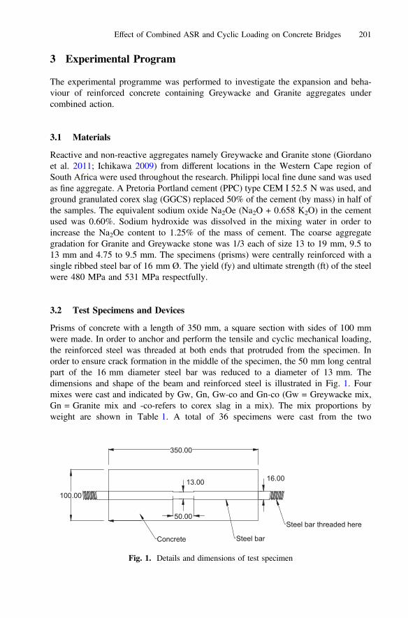
Prisms of concrete with a length of 350 mm, a square section with sides of 100 mmwere made. In order to anchor and perform the tensile and cyclic mechanical loading,the reinforced steel was threaded at both ends that protruded from the specimen. Inorder to ensure crack formation in the middle of the specimen, the 50 mm long centralpart of the 16 mm diameter steel bar was reduced to a diameter of 13 mm. Thedimensions and shape of the beam and reinforced steel is illustrated in Fig. 1. Fourmixes were cast and indicated by Gw, Gn, Gw-co and Gn-co (Gw = Greywacke mix,Gn = Granite mix and -co-refers to corex slag in a mix). The mix proportions byweight are shown in Table 1. A total of 36 specimens were cast from the two
350.00
16.00
50.00
13.00
100.00
Concrete
Steel bar threaded here
Steel bar
Fig. 1. Details and dimensions of test specimen
Effect of Combined ASR and Cyclic Loading on Concrete Bridges 201
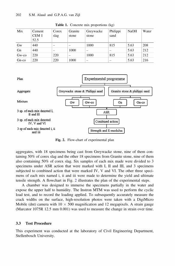
aggregates, with 18 specimens being cast from Greywacke stone, nine of them con-taining 50% of corex slag and the other 18 specimens from Granite stone, nine of themalso containing 50% of corex slag. Six samples of each mix made were divided to 3specimens under ASR action that were marked with I, II and III, and 3 specimenssubjected to combined action that were marked IV, V and VI. The other three speci-mens of each mix named i, ii and iii were made to determine the yield and ultimatetensile strength. A flowchart in Fig. 2 illustrates the plan of the experimental steps.
A chamber was designed to immerse the specimens partially in the water andexpose the upper half to humidity. The Instron MTM was used to perform the cyclicload test, and to record the loading applied. To subsequently accurately measure thecrack widths on the surface, high-resolution photos were taken with a DigiMicroMobile (dnt) camera with 10 � 500 magnification and 12 megapixels. A strain gauge(Marcator 1075R 12.5 mm 0.001) was used to measure the change in strain over time.
3.3 Test Procedure
This experiment was conducted at the laboratory of Civil Engineering Department,Stellenbosch University.
Table 1. Concrete mix proportions (kg)
Mix CementCEM I52.5
Corexslag
Granitestone
Greywackestone
Philippisand
NaOH Water
Gw 440 – – 1000 815 5.63 208Gn 440 – 1000 – – 5.63 212Gw-co 220 220 – 1000 815 5.63 212Gn-co 220 220 1000 – – 5.63 216
Fig. 2. Flow-chart of experimental plan
202 S.M. Alaud and G.P.A.G. van Zijl
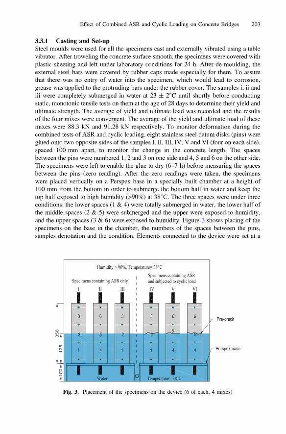
3.3.1 Casting and Set-upSteel moulds were used for all the specimens cast and externally vibrated using a tablevibrator. After troweling the concrete surface smooth, the specimens were covered withplastic sheeting and left under laboratory conditions for 24 h. After de-moulding, theexternal steel bars were covered by rubber caps made especially for them. To assurethat there was no entry of water into the specimen, which would lead to corrosion,grease was applied to the protruding bars under the rubber cover. The samples i, ii andiii were completely submerged in water at 23 ± 2°C until shortly before conductingstatic, monotonic tensile tests on them at the age of 28 days to determine their yield andultimate strength. The average of yield and ultimate load was recorded and the resultsof the four mixes were convergent. The average of the yield and ultimate load of thesemixes were 88.3 kN and 91.28 kN respectively. To monitor deformation during thecombined tests of ASR and cyclic loading, eight stainless steel datum disks (pins) wereglued onto two opposite sides of the samples I, II, III, IV, V and VI (four on each side),spaced 100 mm apart, to monitor the change in the concrete length. The spacesbetween the pins were numbered 1, 2 and 3 on one side and 4, 5 and 6 on the other side.The specimens were left to enable the glue to dry (6–7 h) before measuring the spacesbetween the pins (zero reading). After the zero readings were taken, the specimenswere placed vertically on a Perspex base in a specially built chamber at a height of100 mm from the bottom in order to submerge the bottom half in water and keep thetop half exposed to high humidity (>90%) at 38°C. The three spaces were under threeconditions: the lower spaces (1 & 4) were totally submerged in water, the lower half ofthe middle spaces (2 & 5) were submerged and the upper were exposed to humidity,and the upper spaces (3 & 6) were exposed to humidity. Figure 3 shows placing of thespecimens on the base in the chamber, the numbers of the spaces between the pins,samples denotation and the condition. Elements connected to the device were set at a
1
2
3
4
5
6
1
2
3
1
2
3
4
5
6
4
5
6
Specimens containing ASR onlySpecimens containing ASRand subjected to cyclic load
Humidity > 90%, Temperature= 38°C
Water Temperature= 38°C100
175
350
Perspex base
Pre-crack
I II III IV V VI
Fig. 3. Placement of the specimens on the device (6 of each, 4 mixes)
Effect of Combined ASR and Cyclic Loading on Concrete Bridges 203
temperature at 38°C according to ASTM C 1293. To keep the level of water constant, afloat was connected to compensate for the loss of water. From each of the four mixes,the specimens denoted I, II, and III were left in the described accelerated ASR exposurecondition (ASR) and the ones named IV, V, and VI were subjected to cyclic loadingwith ASR (combined action) at 28 days.
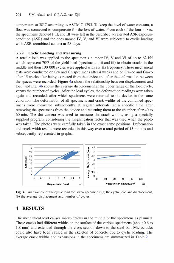
3.3.2 Cyclic Loading and MeasuringA tensile load was applied to the specimen’s number IV, V and VI of up to 62 kNwhich represent 70% of the yield load (specimens i, ii and iii) to obtain cracks in themiddle and then 100 000 cycles were applied with a 5 Hz frequency. These mechanicaltests were conducted on Gw and Gn specimens after 4 weeks and on Gw-co and Gn-coafter 15 weeks after being extracted from the device and after the deformation betweenthe spaces were recorded. Figure 4a shows the relationship between displacement andload, and Fig. 4b shows the average displacement at the upper range of the load cycle,versus the number of cycles. After the load cycles, the deformation readings were takenagain and recorded, after which specimens were returned to the device in the samecondition. The deformation of all specimens and crack widths of the combined spec-imens were measured subsequently at regular intervals, at a specific time afterremoving the specimens from the device and returning them to the chamber after 40 to60 min. The dnt camera was used to measure the crack widths, using a speciallysupplied program, considering the magnification factor that was used when the photowas taken. The photos were carefully taken in the exact same positions. Deformationand crack width results were recorded in this way over a total period of 15 months andsubsequently represented in graphs.
4 RESULTS
The mechanical load causes macro cracks in the middle of the specimens as planned.These cracks had different widths on the surface of the various specimens (about 0.6 to1.8 mm) and extended through the cross section down to the steel bar. Microcrackscould also have been caused in the skeleton of concrete due to cyclic loading. Theaverage crack widths and expansions in the specimens are summarized in Table 2.
Fig. 4. An example of the cyclic load for Gw/w specimens: (a) the cyclic load and displacement,(b) the average displacement and number of cycles.
204 S.M. Alaud and G.P.A.G. van Zijl
4.1 Greywacke Mixes (Gw)
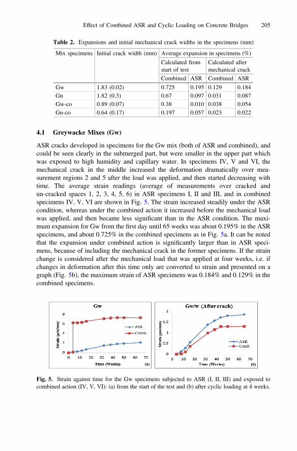
ASR cracks developed in specimens for the Gw mix (both of ASR and combined), andcould be seen clearly in the submerged part, but were smaller in the upper part whichwas exposed to high humidity and capillary water. In specimens IV, V and VI, themechanical crack in the middle increased the deformation dramatically over mea-surement regions 2 and 5 after the load was applied, and then started decreasing withtime. The average strain readings (average of measurements over cracked andun-cracked spaces 1, 2, 3, 4, 5, 6) in ASR specimens I, II and III, and in combinedspecimens IV, V, VI are shown in Fig. 5. The strain increased steadily under the ASRcondition, whereas under the combined action it increased before the mechanical loadwas applied, and then became less significant than in the ASR condition. The maxi-mum expansion for Gw from the first day until 65 weeks was about 0.195% in the ASRspecimens, and about 0.725% in the combined specimens as in Fig. 5a. It can be notedthat the expansion under combined action is significantly larger than in ASR speci-mens, because of including the mechanical crack in the former specimens. If the strainchange is considered after the mechanical load that was applied at four weeks, i.e. ifchanges in deformation after this time only are converted to strain and presented on agraph (Fig. 5b), the maximum strain of ASR specimens was 0.184% and 0.129% in thecombined specimens.
Table 2. Expansions and initial mechanical crack widths in the specimens (mm)
Mix specimens Initial crack width (mm) Average expansion in specimens (%)
Calculated fromstart of test
Calculated aftermechanical crack
Combined ASR Combined ASR
Gw 1.83 (0.02) 0.725 0.195 0.129 0.184Gn 1.82 (0.3) 0.67 0.097 0.031 0.087Gw-co 0.89 (0.07) 0.38 0.010 0.038 0.054Gn-co 0.64 (0.17) 0.197 0.057 0.023 0.022
Fig. 5. Strain against time for the Gw specimens subjected to ASR (I, II, III) and exposed tocombined action (IV, V, VI): (a) from the start of the test and (b) after cyclic loading at 4 weeks.
Effect of Combined ASR and Cyclic Loading on Concrete Bridges 205
4.2 Granite Mixes (Gn)
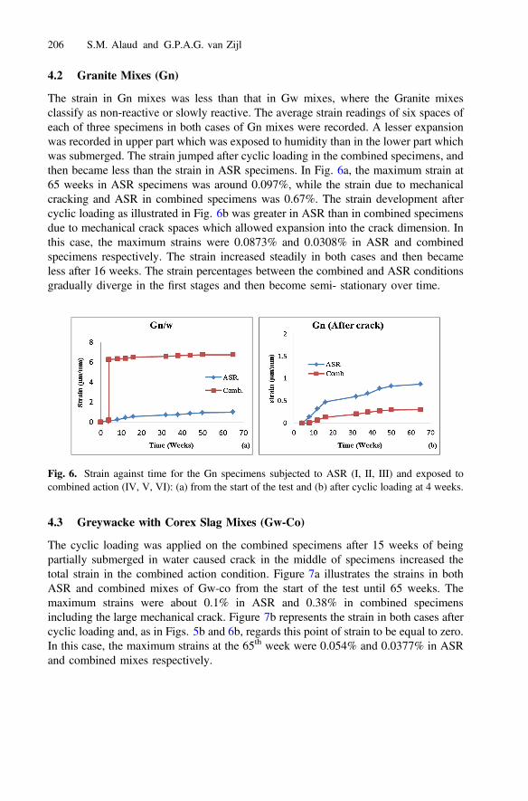
The strain in Gn mixes was less than that in Gw mixes, where the Granite mixesclassify as non-reactive or slowly reactive. The average strain readings of six spaces ofeach of three specimens in both cases of Gn mixes were recorded. A lesser expansionwas recorded in upper part which was exposed to humidity than in the lower part whichwas submerged. The strain jumped after cyclic loading in the combined specimens, andthen became less than the strain in ASR specimens. In Fig. 6a, the maximum strain at65 weeks in ASR specimens was around 0.097%, while the strain due to mechanicalcracking and ASR in combined specimens was 0.67%. The strain development aftercyclic loading as illustrated in Fig. 6b was greater in ASR than in combined specimensdue to mechanical crack spaces which allowed expansion into the crack dimension. Inthis case, the maximum strains were 0.0873% and 0.0308% in ASR and combinedspecimens respectively. The strain increased steadily in both cases and then becameless after 16 weeks. The strain percentages between the combined and ASR conditionsgradually diverge in the first stages and then become semi- stationary over time.
4.3 Greywacke with Corex Slag Mixes (Gw-Co)
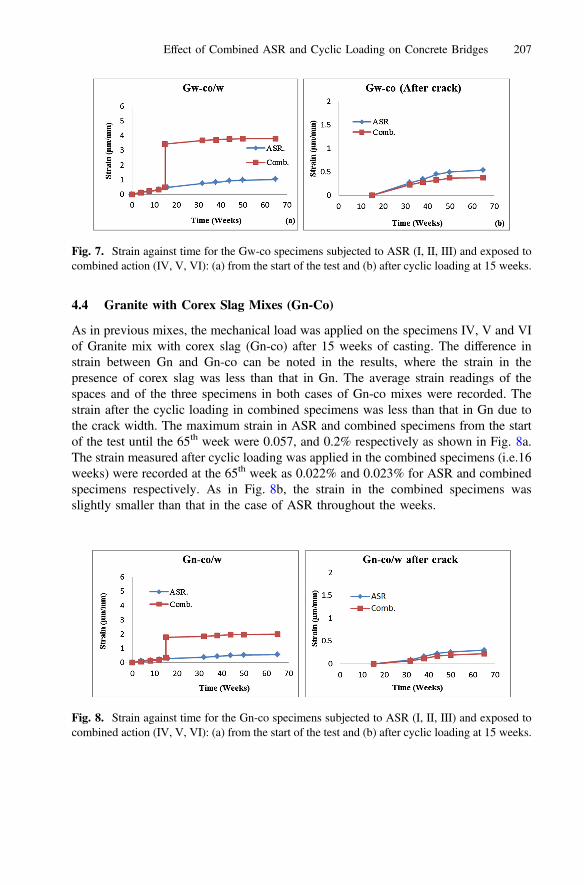
The cyclic loading was applied on the combined specimens after 15 weeks of beingpartially submerged in water caused crack in the middle of specimens increased thetotal strain in the combined action condition. Figure 7a illustrates the strains in bothASR and combined mixes of Gw-co from the start of the test until 65 weeks. Themaximum strains were about 0.1% in ASR and 0.38% in combined specimensincluding the large mechanical crack. Figure 7b represents the strain in both cases aftercyclic loading and, as in Figs. 5b and 6b, regards this point of strain to be equal to zero.In this case, the maximum strains at the 65th week were 0.054% and 0.0377% in ASRand combined mixes respectively.
Fig. 6. Strain against time for the Gn specimens subjected to ASR (I, II, III) and exposed tocombined action (IV, V, VI): (a) from the start of the test and (b) after cyclic loading at 4 weeks.
206 S.M. Alaud and G.P.A.G. van Zijl
4.4 Granite with Corex Slag Mixes (Gn-Co)
As in previous mixes, the mechanical load was applied on the specimens IV, V and VIof Granite mix with corex slag (Gn-co) after 15 weeks of casting. The difference instrain between Gn and Gn-co can be noted in the results, where the strain in thepresence of corex slag was less than that in Gn. The average strain readings of thespaces and of the three specimens in both cases of Gn-co mixes were recorded. Thestrain after the cyclic loading in combined specimens was less than that in Gn due tothe crack width. The maximum strain in ASR and combined specimens from the startof the test until the 65th week were 0.057, and 0.2% respectively as shown in Fig. 8a.The strain measured after cyclic loading was applied in the combined specimens (i.e.16weeks) were recorded at the 65th week as 0.022% and 0.023% for ASR and combinedspecimens respectively. As in Fig. 8b, the strain in the combined specimens wasslightly smaller than that in the case of ASR throughout the weeks.
Fig. 7. Strain against time for the Gw-co specimens subjected to ASR (I, II, III) and exposed tocombined action (IV, V, VI): (a) from the start of the test and (b) after cyclic loading at 15 weeks.
Fig. 8. Strain against time for the Gn-co specimens subjected to ASR (I, II, III) and exposed tocombined action (IV, V, VI): (a) from the start of the test and (b) after cyclic loading at 15 weeks.
Effect of Combined ASR and Cyclic Loading on Concrete Bridges 207
4.5 Mechanical Crack Width
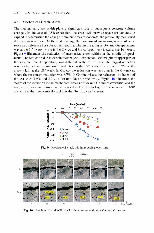
The mechanical crack width plays a significant role in subsequent concrete volumechanges. In the case of ASR expansion, the crack will provide space for concrete toexpand. To determine the change in the pre-cracked concrete, the previously mentioneddnt camera was used. At the first reading, the position of measuring was marked toserve as a reference for subsequent reading. The first reading in Gw and Gn specimenswas at the 10th week, while in the Gw-co and Gn-co specimens it was at the 16th week.Figure 9 illustrates the reduction of mechanical crack widths in the middle of speci-mens. The reduction due to certain factors (ASR expansion, self-weight of upper part ofthe specimen and temperature) was different in the four mixes. The largest reductionwas in Gw, where the maximum reduction at the 65th week was around 23.7% of thecrack width at the 10th week. In Gw-co, the reduction was less than in the Gw mixes,where the maximum reduction was 8.7%. In Granite mixes, the reductions at the end ofthe test were 7.9% and 8.7% in Gn and Gn-co respectively. Figure 10 illustrates thestages of the reduction in the mechanical cracks of Gw and Gn mixes over time, and thestages of Gw-co and Gn-co are illustrated in Fig. 11. In Fig. 10 the increase in ASRcracks, i.e. the fine, vertical cracks in the Gw mix can be seen.
Fig. 9. Mechanical crack widths reducing over time
ASR crack
66.5 84.7 105.9 113.4 115.6
10 32 38 44 50 65
Gw
Gn
Time (Week)
0 5000 10000 μm
Fig. 10. Mechanical and ASR cracks changing over time in Gw and Gn mixes
208 S.M. Alaud and G.P.A.G. van Zijl
Gn-co
Gw-co
32 50 65 Time (Week)16
0 5000 10000 μm
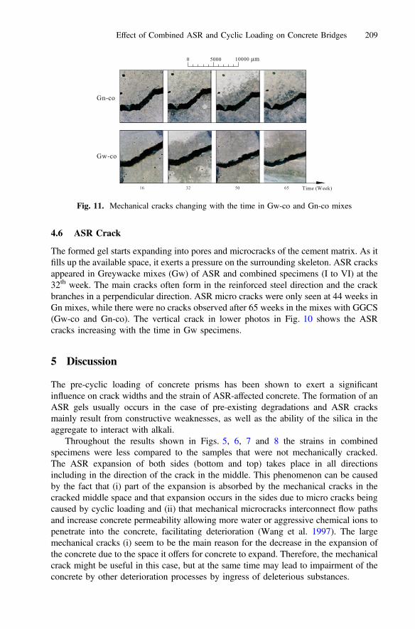
Fig. 11. Mechanical cracks changing with the time in Gw-co and Gn-co mixes
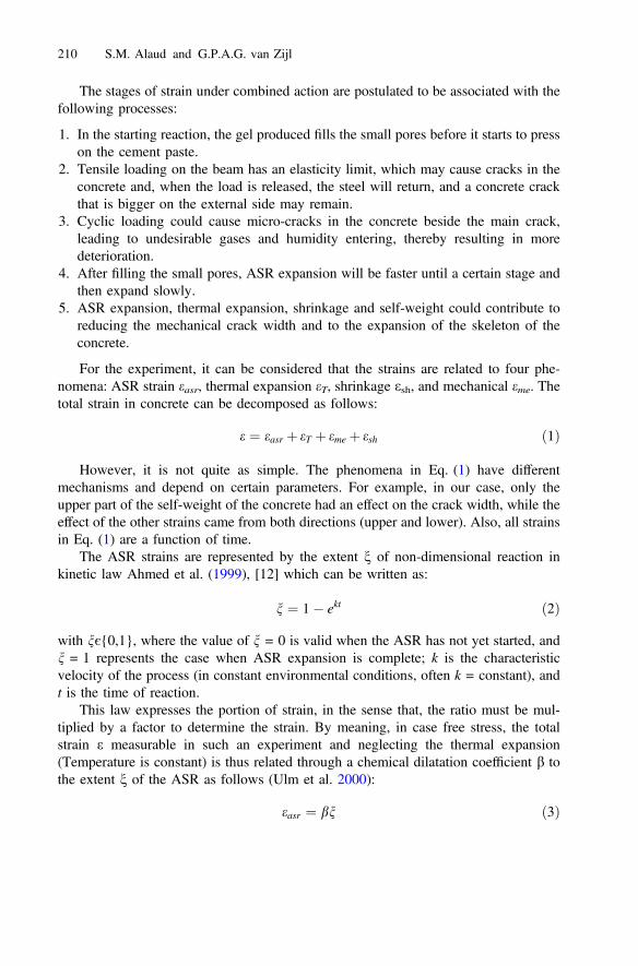
4.6 ASR Crack
The formed gel starts expanding into pores and microcracks of the cement matrix. As itfills up the available space, it exerts a pressure on the surrounding skeleton. ASR cracksappeared in Greywacke mixes (Gw) of ASR and combined specimens (I to VI) at the32th week. The main cracks often form in the reinforced steel direction and the crackbranches in a perpendicular direction. ASR micro cracks were only seen at 44 weeks inGn mixes, while there were no cracks observed after 65 weeks in the mixes with GGCS(Gw-co and Gn-co). The vertical crack in lower photos in Fig. 10 shows the ASRcracks increasing with the time in Gw specimens.
5 Discussion
The pre-cyclic loading of concrete prisms has been shown to exert a significantinfluence on crack widths and the strain of ASR-affected concrete. The formation of anASR gels usually occurs in the case of pre-existing degradations and ASR cracksmainly result from constructive weaknesses, as well as the ability of the silica in theaggregate to interact with alkali.
Throughout the results shown in Figs. 5, 6, 7 and 8 the strains in combinedspecimens were less compared to the samples that were not mechanically cracked.The ASR expansion of both sides (bottom and top) takes place in all directionsincluding in the direction of the crack in the middle. This phenomenon can be causedby the fact that (i) part of the expansion is absorbed by the mechanical cracks in thecracked middle space and that expansion occurs in the sides due to micro cracks beingcaused by cyclic loading and (ii) that mechanical microcracks interconnect flow pathsand increase concrete permeability allowing more water or aggressive chemical ions topenetrate into the concrete, facilitating deterioration (Wang et al. 1997). The largemechanical cracks (i) seem to be the main reason for the decrease in the expansion ofthe concrete due to the space it offers for concrete to expand. Therefore, the mechanicalcrack might be useful in this case, but at the same time may lead to impairment of theconcrete by other deterioration processes by ingress of deleterious substances.
Effect of Combined ASR and Cyclic Loading on Concrete Bridges 209
The stages of strain under combined action are postulated to be associated with thefollowing processes:
1. In the starting reaction, the gel produced fills the small pores before it starts to presson the cement paste.
2. Tensile loading on the beam has an elasticity limit, which may cause cracks in theconcrete and, when the load is released, the steel will return, and a concrete crackthat is bigger on the external side may remain.
3. Cyclic loading could cause micro-cracks in the concrete beside the main crack,leading to undesirable gases and humidity entering, thereby resulting in moredeterioration.
4. After filling the small pores, ASR expansion will be faster until a certain stage andthen expand slowly.
5. ASR expansion, thermal expansion, shrinkage and self-weight could contribute toreducing the mechanical crack width and to the expansion of the skeleton of theconcrete.
For the experiment, it can be considered that the strains are related to four phe-nomena: ASR strain easr, thermal expansion eT, shrinkage esh, and mechanical eme. Thetotal strain in concrete can be decomposed as follows:
e ¼ easr þ eT þ eme þ esh ð1Þ
However, it is not quite as simple. The phenomena in Eq. (1) have differentmechanisms and depend on certain parameters. For example, in our case, only theupper part of the self-weight of the concrete had an effect on the crack width, while theeffect of the other strains came from both directions (upper and lower). Also, all strainsin Eq. (1) are a function of time.
The ASR strains are represented by the extent n of non-dimensional reaction inkinetic law Ahmed et al. (1999), [12] which can be written as:
n ¼ 1� ekt ð2Þ
with nє{0,1}, where the value of n = 0 is valid when the ASR has not yet started, andn = 1 represents the case when ASR expansion is complete; k is the characteristicvelocity of the process (in constant environmental conditions, often k = constant), andt is the time of reaction.
This law expresses the portion of strain, in the sense that, the ratio must be mul-tiplied by a factor to determine the strain. By meaning, in case free stress, the totalstrain e measurable in such an experiment and neglecting the thermal expansion(Temperature is constant) is thus related through a chemical dilatation coefficient b tothe extent n of the ASR as follows (Ulm et al. 2000):
easr ¼ bn ð3Þ
210 S.M. Alaud and G.P.A.G. van Zijl
and
b ¼ cEg
Eð4Þ
where Eg and E are the modulus of elasticity of the gel and the concrete respectively,and c is the intrinsic dilatation coefficient of the reaction products.
In order to model the ASR in concrete induced with a mechanical crack, the periodshould be divided into two stages: before the mechanical crack and after that.Neglecting the change in cross-section, the longitudinal change Δl in concrete due toASR and mechanical actions can be described by:
Dl tð Þ ¼ Dli tið ÞþCw tmcr� �þDlf tf
� � ð5Þ
where Δli is the ASR expansion before the mechanical crack, Cw, mechanical crackwidth, Δlf, expansion after mechanical crack occurred and ti, tme, and tf, the initialreaction time before mechanical crack, mechanical crack time and the final reactiontime respectively.
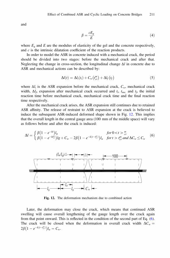
After the mechanical crack arises, the ASR expansion still continues due to retainedASR affinity. The release of restraint to ASR expansion at the crack is believed toinduce the subsequent ASR-induced deformed shape shown in Fig. 12. This impliesthat the overall length in the central gauge area (100 mm of the middle space) will varyas follows before and after the crack is induced:
Dl ¼ b 1� e�kt� �
lg for 0\t[ mcr
b 1� e�ktmcr� �
lgþCw � 2b 1� e�kðt�tmcrÞ� �
la for t[ tmcr and DCw �Cw
�ð6Þ
Later, the deformation may close the crack, which means that continued ASRswelling will cause overall lengthening of the gauge length over the crack againfrom that point onward. This is reflected in the condition of the second part of Eq. (6).The crack will be closed when the deformation in overall crack width DCw ¼2b 1� e�kðt�tmcrÞ
� �la ¼ Cw.
Cwlblbla
(la/lb) 100
Fig. 12. The deformation mechanism due to combined action
Effect of Combined ASR and Cyclic Loading on Concrete Bridges 211
From the same graph, the surface crack width reduction in time can be expressedas:
Cw tð Þ ¼ Cw � 2b 1� e�kðt�tmcrÞ� �
lb for t[ tmcr and Cw tð Þ� 0 ð7Þ
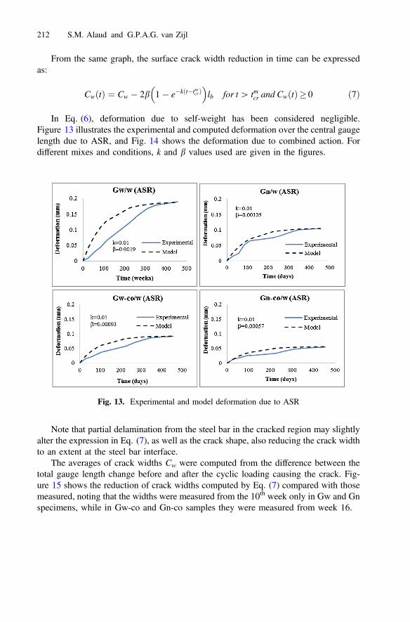
In Eq. (6), deformation due to self-weight has been considered negligible.Figure 13 illustrates the experimental and computed deformation over the central gaugelength due to ASR, and Fig. 14 shows the deformation due to combined action. Fordifferent mixes and conditions, k and b values used are given in the figures.
Note that partial delamination from the steel bar in the cracked region may slightlyalter the expression in Eq. (7), as well as the crack shape, also reducing the crack widthto an extent at the steel bar interface.
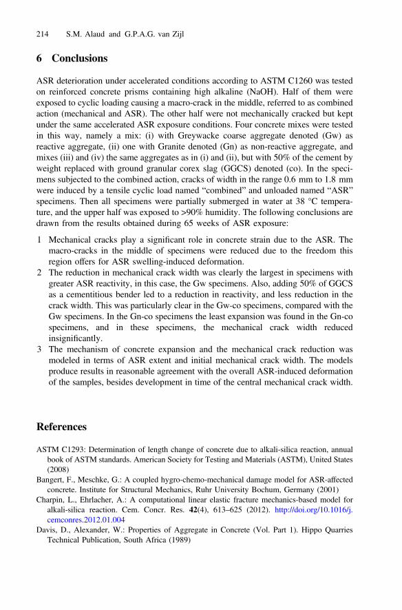
The averages of crack widths Cw were computed from the difference between thetotal gauge length change before and after the cyclic loading causing the crack. Fig-ure 15 shows the reduction of crack widths computed by Eq. (7) compared with thosemeasured, noting that the widths were measured from the 10th week only in Gw and Gnspecimens, while in Gw-co and Gn-co samples they were measured from week 16.
Fig. 13. Experimental and model deformation due to ASR
212 S.M. Alaud and G.P.A.G. van Zijl
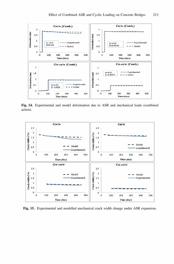
Fig. 14. Experimental and model deformation due to ASR and mechanical loads (combinedaction).
Fig. 15. Experimental and modelled mechanical crack width change under ASR expansion.
Effect of Combined ASR and Cyclic Loading on Concrete Bridges 213
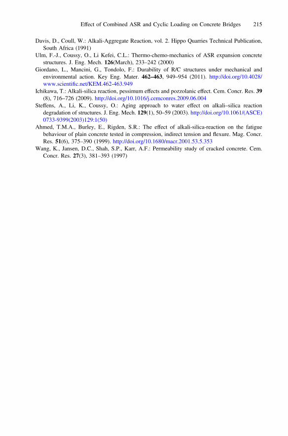
6 Conclusions
ASR deterioration under accelerated conditions according to ASTM C1260 was testedon reinforced concrete prisms containing high alkaline (NaOH). Half of them wereexposed to cyclic loading causing a macro-crack in the middle, referred to as combinedaction (mechanical and ASR). The other half were not mechanically cracked but keptunder the same accelerated ASR exposure conditions. Four concrete mixes were testedin this way, namely a mix: (i) with Greywacke coarse aggregate denoted (Gw) asreactive aggregate, (ii) one with Granite denoted (Gn) as non-reactive aggregate, andmixes (iii) and (iv) the same aggregates as in (i) and (ii), but with 50% of the cement byweight replaced with ground granular corex slag (GGCS) denoted (co). In the speci-mens subjected to the combined action, cracks of width in the range 0.6 mm to 1.8 mmwere induced by a tensile cyclic load named “combined” and unloaded named “ASR”specimens. Then all specimens were partially submerged in water at 38 °C tempera-ture, and the upper half was exposed to >90% humidity. The following conclusions aredrawn from the results obtained during 65 weeks of ASR exposure:
1 Mechanical cracks play a significant role in concrete strain due to the ASR. Themacro-cracks in the middle of specimens were reduced due to the freedom thisregion offers for ASR swelling-induced deformation.
2 The reduction in mechanical crack width was clearly the largest in specimens withgreater ASR reactivity, in this case, the Gw specimens. Also, adding 50% of GGCSas a cementitious bender led to a reduction in reactivity, and less reduction in thecrack width. This was particularly clear in the Gw-co specimens, compared with theGw specimens. In the Gn-co specimens the least expansion was found in the Gn-cospecimens, and in these specimens, the mechanical crack width reducedinsignificantly.
3 The mechanism of concrete expansion and the mechanical crack reduction wasmodeled in terms of ASR extent and initial mechanical crack width. The modelsproduce results in reasonable agreement with the overall ASR-induced deformationof the samples, besides development in time of the central mechanical crack width.
References
ASTM C1293: Determination of length change of concrete due to alkali-silica reaction, annualbook of ASTM standards. American Society for Testing and Materials (ASTM), United States(2008)
Bangert, F., Meschke, G.: A coupled hygro-chemo-mechanical damage model for ASR-affectedconcrete. Institute for Structural Mechanics, Ruhr University Bochum, Germany (2001)
Charpin, L., Ehrlacher, A.: A computational linear elastic fracture mechanics-based model foralkali-silica reaction. Cem. Concr. Res. 42(4), 613–625 (2012). http://doi.org/10.1016/j.cemconres.2012.01.004
Davis, D., Alexander, W.: Properties of Aggregate in Concrete (Vol. Part 1). Hippo QuarriesTechnical Publication, South Africa (1989)
214 S.M. Alaud and G.P.A.G. van Zijl
Davis, D., Coull, W.: Alkali-Aggregate Reaction, vol. 2. Hippo Quarries Technical Publication,South Africa (1991)
Ulm, F.-J., Coussy, O., Li Kefei, C.L.: Thermo-chemo-mechanics of ASR expansion concretestructures. J. Eng. Mech. 126(March), 233–242 (2000)
Giordano, L., Mancini, G., Tondolo, F.: Durability of R/C structures under mechanical andenvironmental action. Key Eng. Mater. 462–463, 949–954 (2011). http://doi.org/10.4028/www.scientific.net/KEM.462-463.949
Ichikawa, T.: Alkali-silica reaction, pessimum effects and pozzolanic effect. Cem. Concr. Res. 39(8), 716–726 (2009). http://doi.org/10.1016/j.cemconres.2009.06.004
Steffens, A., Li, K., Coussy, O.: Aging approach to water effect on alkali–silica reactiondegradation of structures. J. Eng. Mech. 129(1), 50–59 (2003). http://doi.org/10.1061/(ASCE)0733-9399(2003)129:1(50)
Ahmed, T.M.A., Burley, E., Rigden, S.R.: The effect of alkali-silica-reaction on the fatiguebehaviour of plain concrete tested in compression, indirect tension and flexure. Mag. Concr.Res. 51(6), 375–390 (1999). http://doi.org/10.1680/macr.2001.53.5.353
Wang, K., Jansen, D.C., Shah, S.P., Karr, A.F.: Permeability study of cracked concrete. Cem.Concr. Res. 27(3), 381–393 (1997)
Effect of Combined ASR and Cyclic Loading on Concrete Bridges 215


![Constructiegedrag van door ASR aangetaste viaducten, … · 2017-10-24 · December 6, 2015 2. ASR-gel [1] uitbloeiingen ASR-gel December 6, 2015 3 Typisch scheurenpatroon ASR [1]](https://img.pdfslide.us/doc/110x75/5b317ef97f8b9a744a8bd127/constructiegedrag-van-door-asr-aangetaste-viaducten-2017-10-24-december.jpg)