Embed Size (px)
Citation preview

EJERS, European Journal of Engineering Research and Science
Vol. 4, No. 9, September 2019
DOI: http://dx.doi.org/10.24018/ejers.2019.4.9.1533 181
Abstract—. Industrial fans are subject to European Union
energy labeling and Ecodesign requirements. By using more
efficient industrial fans, Europe will save 34 TWh and avoid 16
million tons of CO2 emissions annually by 2020 [1]. In this
paper, the effect of the clearance gap between the impeller and
the volute, on the performance of a centrifugal fan was
investigated using open source CFD software OpenFOAM [2].
An automized loop with RANS and data post-processing is set
up using Matlab, for allowing a large number of parameter
variations. We conducted numerical analysis for all operating
points, where starting points are optimal impellers for the
whole range of specific speeds [3], [4]. The effect of volute angle
and geometrical parameters related to the tongue [5], on total
pressure loss, static pressure recovery coefficient and on
efficiency are presented.
Index Terms—CFD, Clearance Gap, Efficiency, Volute.
I. INTRODUCTION
Many articles related to centrifugal fans have studied and
optimized only the fan impeller and some of them treat the
fan as a whole unit, while the study of the spiral casing is
less well-known. From the literature it is known that the
spiral casing can take large part of the hydraulic losses in the
fan. Minimization of energy loss depends on the
characteristics of the spiral casing. Hence, appropriate
design of the fan spiral casing has significant meaning to
centrifugal fan performance.
For this reason, this study of the effect of the clearance
gap has been conducted, which should lead to better
advanced recommendations for the shape of the spiral
casing.
II. VOLUTE SHAPE DESIGN METHOD
Constant circulation method [6] is a method applied by
drawing a spiral case based on the fact that velocity
circulation is a constant rcu = 𝑐𝑜𝑛𝑠𝑡𝑎𝑛𝑡. In practice, this
rule is valid with the restriction that one spiral must be so far
displaced from the impeller that deflections conditioned by
the consideration of a finite number of blades can be
ignored. This rule constitutes the basis for the dimensioning
of a volute in the cases where friction has been ignored. The
velocity c at an arbitrary place can be calculated from its
components 𝑐𝑚 and 𝑐𝑢 , 𝑟𝑐𝑢 = 𝑟2𝑐𝑢2. From the condition that
the same volume-flow must flow (the continuity equation)
through all the streamline in volute it gives the correlation:
Published on September 26, 2019.
A. Gjeta is with Energy Department, Faculty of Mechanical
Engineering, Polytechnic University of Tirana, Tirana, Albania. (e-mail:
𝑄 = 2𝜋𝑟2𝑏2𝑐𝑚2 = 2𝜋𝑟𝐵𝑐𝑚 (1)
From which follows 𝑟2𝑏2𝑐𝑚2 = 𝑟𝐵𝑐𝑚 , from this we
obtain the following inclination of the streamlines:
𝑡𝑔(𝛼) =𝑐𝑚
𝑐𝑢
=𝑐𝑚2
𝑐𝑢2
𝑏2
𝐵 (2)
Because we obtain the boundary of the volute from the
streamline, again it yields, 𝑡𝑔(𝛼) =𝑑𝑟
𝑟𝑑𝜑;
𝑑𝑟
𝑟= 𝑑𝜑 𝑡𝑔(𝛼) = 𝑑𝜑 𝑡𝑔(𝛼2)
𝑏2
𝐵 (3)
The solution states,
𝑙𝑛𝑟
𝑟2
= 𝜑 𝑡𝑔(𝛼2)𝑏2
𝐵= 𝜑
𝑐𝑚2
𝑐𝑢2
𝑏2
𝐵 (4)
Accordingly, the trajectory of fluid particles in the volute
is as follows (Carolus 2013) [7],
𝑟(𝜑) = 𝑟2𝑒𝜑𝑡𝑔(𝛼) = 𝑟2𝑒𝜑𝑡𝑔(𝛼2)𝑏2𝐵 (5)
𝑟(𝜑), is the radius of the volute at an angle 𝜑,
𝑟2, is the outer radius of the impeller that is equal to
150mm in our case
𝛼, is the angle that the absolute velocity vector makes
with the peripheral direction 𝑡𝑔(𝛼) = 𝑐𝑚/𝑐𝑢.
𝑏2, the width of outlet impeller
𝐵, the width of volute
Fig. 1. Geometry parameters of the spiral casing (Carolus 2013) [3]
In this study, is shown the effect of clearance gap on the
performance of the centrifugal fan by using open source
CFD software OpenFOAM. A qualitative understanding of
the effects of parameters will enable the performance of a
real product to be improved.
Effect of Clearance Gap in Spiral Casing Design of a
Centrifugal Fan with Optimized Impellers
Ardit Gjeta
EJERS, European Journal of Engineering Research and Science
Vol. 4, No. 9, September 2019
DOI: http://dx.doi.org/10.24018/ejers.2019.4.9.1533 182
III. PERFORMANCE OF THE VOLUTE
The overall performance of the volute is affected mainly
by the following geometric parameters [5]:
area of the cross-section,
the shape of the cross-section,
radial location of the cross-section,
location of the impeller and
tongue geometry
The overall performance of the volute can be analyzed by
using:
Total pressure loss coefficient of volute:
𝐾𝑝 =𝑝𝑡2 − 𝑝𝑡3
𝑝𝑡2 − 𝑝2
=𝑝𝑡2 − 𝑝𝑡3
𝜌2 𝑐2
2 (6)
𝐾𝑝 is defined as the ratio between the total pressure losses
in the volute to the dynamic pressure at the impeller exit.
Static pressure recovery coefficient of volute:
𝐶𝑝 =𝑝3 − 𝑝2
𝑝𝑡2 − 𝑝2
=𝑝3 − 𝑝2
𝜌2 𝑐2
2 (7)
𝐶𝑝 is defined as the ratio between the static pressure
recovered in the volute to the dynamic pressure at the
impeller exit.
Total efficiency of volute
𝜂𝑇 =𝑝𝑡3
𝑝𝑡2
(8)
From equation (6, 7) becomes:
𝐶𝑝 = 1 − 𝐾𝑝 − (𝑐3
𝑐2
)2
(9)
(𝑐3
𝑐2)
2
, is the ratio of volute outlet/inlet kinetic energy.
Maximizing performance of a complete fan requires,
finding 𝑐3.𝑜𝑝𝑡, 𝐾𝑝.𝑜𝑝𝑡 = 𝐾𝑝.𝑚𝑖𝑛 , 𝐶𝑝.𝑜𝑝𝑡 = 𝐶𝑝.𝑚𝑎𝑥 from CFD
as a function of clearance gap of volute (function of alpha
spiral angle, tongue angle and tongue radius).
IV. NUMERICAL ANALYSIS
The detailed flow field at the impeller’s outlet from
preceding RANS simulations is used as boundary conditions
for a RANS of the flow in the volutes.
Three-dimensional, incompressible, steady-state flow
simulations were performed using the Open Source CFD
software, OpenFOAM v3.0.x [2]. This solves discretized
forms of the Reynolds-averaged Navier–Stokes equations
for turbulent flow using the finite volume method (Ferziger,
Perić 2002) [8].
The unstructured grid solution procedure is based on a
variant of the SIMPLE pressure correction technique
(Patankar 1980) [9]. The iterative solution was deemed to be
converged when the normalized absolute error over the
mesh had reduced to 10−5 for each variable. OpenFOAM
supports the standard k–ω model by Wilcox (1998) [10],
and Menter’s SST k–ω model (1994) [11]. The k-ω SST
turbulence model was employed for these calculations, with
near-wall conditions supplied by the ‘wall function’
conditions of Launder and Spalding, 1974 [12].
V. BOUNDARY AND INITIAL CONDITIONS
The inflow boundary conditions were based on known
flow rates and the flow direction [3], [4]. Nonuniform
velocity profiles were prescribed at the volute inlet (fan
impeller outlet) by implementing radial and tangential
velocity components, also axial velocity is included. The
front and backside of the impeller as the rotating wall, the
other parts wall with the no-slip condition and for the outlet
ambient pressure is used. Turbulent kinetic energy is 𝑘 =3𝑚2𝑠−2, and the specific turbulence dissipation rate is 𝜔 =4000𝑠−1.
The geometry of volutes is generated from MATLAB as
stereolithography (.stl file) than cfMesh v1.1.2 software is
used to create a mesh. The grid resolution is made according
to 𝑦+ value 30 < 𝑦+ < 200.
VI. CFD SIMULATION RESULTS
This study will focus on the effect of the clearance gap
between the rotor and the spiral casing. In our previous
study [4], the influence of parameters is given but separately
and not as a function of the clearance gap. Considering the
design of the spiral casing, clereance gap is a function of the
logarithmic spiral, 𝛼, the angle of the tongue 𝜑𝑧 , and the
radius of the tongue 𝑟𝑧. Since we will study every operation
point of the fan, the angle of spiral casing will vary
from 𝛼 = 12 ÷ 20°. Width of the spiral casing is accepted
constant since this parameter does not affect the clearance
gap value, see Fig. 1. Referring to the literature we will have
references to the values of these parameters that can obtain
[13]. To observe the effect of each parameter, we will first
accept some constant parameters and then continuously
examine the other parameters. We will assume an average
alpha angle value 𝛼 = 16° and the angle of the tongue 𝜑𝑧 =35°.
We will change the radius of the tongue to the values
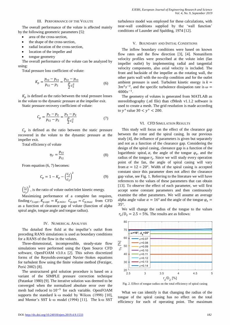
𝑟𝑧/𝐷2 = 2.5 ÷ 5%. The results are as follows:
Fig. 2. Effect of tongue radius on the total efficiency of spiral casing
What we can identify is that changing the radius of the
tongue of the spiral casing has no effect on the total
efficiency for each of operating point. The maximum

EJERS, European Journal of Engineering Research and Science
Vol. 4, No. 9, September 2019
DOI: http://dx.doi.org/10.24018/ejers.2019.4.9.1533 183
efficiency achieved in a spiral casing refers to the flow
coefficient 𝜙 = 0.13 ÷ 0.14. We need to look at the effect
on the static pressure recovery coefficient of the spiral
casing.
Fig. 3. Effect on the static pressure recovery coefficient of the spiral casing
function of the radius of the tongue.
We obtain the same result for the static pressure recovery
coefficient in the spiral casing. But unlike the efficiency of
the spiral casing, the static pressure recovery coefficient gets
the maximum value for the minimum flow coefficient and
the positive value for the flow coefficient from 𝜙 = 0.07 ÷0.12.
Since the radius of the tongue has no effect on the
efficiency then we will consider other parameter values of
the spiral casing tongue. To ensure a minimum safety
clearance distance of 𝑠𝑧
𝐷2= 3.5% [13] it has been accepted as
a minimum tongue angle of 𝜑𝑧 = 35°. The results are as
follows:
Fig. 4. Total efficiency of the spiral casing as a function of flow coefficient
From Fig. 4, we observe a continuous increase in
efficiency as the flow coefficient increases, and this trend is
the same for each tongue angle value. Except with
increasing the angle of the tongue 𝜑𝑧, we will decrease the
total efficiency of the spiral casing.
Fig. 5. Static pressure recovery coefficient as a function of flow coefficient
If we observe the static pressure recovery values, we can
see that for the minimum flow coefficient, the maximum
pressure recovery values are obtained. In this case, with the
increase in the angle of the spiral casing tongue, there is also
an increase in the values of the static pressure recovery
coefficient. The optimum maximum value is obtained for
the flow coefficient of 𝜙 = 0.07 ÷ 0.08. If we refer to the
large values of the flow coefficient, negative values of the
static pressure recovery coefficient are also observed.
However, to have a better understanding of the behavior
of each parameter, we must also see at the total pressure loss
coefficient.
Fig. 6. Total pressure loss coefficient as a function of flow coefficient
Since for the total pressure loss coefficient is required a
value as small as possible, therefore the optimal values are
in the range of flow coefficient from 𝜙 = 0.10 ÷ 0.11. This
is the recommended working area of this type of fan with
this type of spiral casing. If we move beyond this work area,
the value of pressure losses will be higher. It is important to
note that for the flow coefficient ϕ = 0.07 ÷ 0.10, the
minimum value of 𝐾𝑝 is for tongue angle 𝜑𝑧 = 60°, whereas
for 𝜙 = 0.11 ÷ 0.14, the minimum value of 𝐾𝑝 is for 𝜑𝑧 =
35°.
Another parameter that influenced the safety space
between the rotor and the spiral casing is the logarithmic
alpha angle. We have accepted 2 limit values, for compact
spiral casing we have chosen 12-degree alpha angle
(providing minimum security space) and for large spiral
casing 20-degree angle. Since the alpha angle directly
affects the spiral casing size, if we increase the alpha angle
we expect to have a low-efficiency value and an increased
value in the static pressure recovery coefficient. In order to
determine the optimal working point of the spiral casing, we
must refer to the values of the total pressure loss coefficient.

EJERS, European Journal of Engineering Research and Science
Vol. 4, No. 9, September 2019
DOI: http://dx.doi.org/10.24018/ejers.2019.4.9.1533 184
Fig. 7. Total pressure loss coefficient as a function of flow coefficient
For each of the logarithmic spiral alpha angles, we have a
minimum optimum value of the total pressure loss
coefficient. And in this case, the recommended values of the
working point are in the range 𝜙 = 0.09 ÷ 0.12.
To verify this value another parameter called the ratio of
the output/input kinetic energy (𝑐3
𝑐2)
2
, must be considered,
where it must be ensured that this ratio is less than 1. The
graph below shows that for the alpha angle 12 degree, the
ratio (𝑐3
𝑐2)
2
is less than 1 for the flow coefficient value
of 𝜙 < 0.12.
Fig. 8. Output/input kinetic energy as a function of flow coefficient
Since in this study we presented the effect of 3 different
parameters, in particular, the effect of the clearance gap has
to be shown as a parameter which is a function of the above
three parameters 𝑠𝑧 = 𝑓(𝛼, 𝑟𝑧 , 𝜑𝑧).
Fig. 9. Total efficiency of the spiral casing as a function of clearance gap
If we have a small value of clearance gap between the
rotor and the spiral casing, we will have high values of total
efficiency, but we cannot go beyond the value of 3.5% due
to security reasons [14]. If we refer to the flow coefficient,
with its increase we will have an increase in the total
efficiency of the spiral casing.
Fig. 10. Total pressure loss coefficient of the spiral casing as a function of
the clearance gap
Since the recommended values of the flow coefficient
were 𝜙 = 0.09 ÷ 0.12, we are only presenting the results
below for these values.
Fig. 11. Total pressure loss coefficient of the spiral casing as a function of
the clearance gap
If we notice the recommended interval of fan working
point for this type of spiral casing, it is observed that for the
flow coefficient of 𝜙 = 0.09, the minimum value of 𝐾𝑝 is
in the range 𝑠𝑧
𝐷2= 4.5 ÷ 5%. For the value of the flow
coefficient of 𝜙 = 0.10, the minimum value is reached for
clearance gap around 𝑠𝑧
𝐷2= 5.25 ÷ 5.75%, whereas for the
flow coefficient of 𝜙 = 0.11 ÷ 0.12, the smallest value of
the total pressure loss coefficient is observed for clearance
gap around 𝑠𝑧
𝐷2= 6.6 ÷ 7.5%.
VII. CONCLUSION
From the results of numerical simulations, we come to the
following conclusions:
The radius of the tongue has no effect on the total
efficiency, on static pressure recovery coefficient and
on total pressure loss coefficient of the spiral casing.
Maximum efficiency is achieved for flow
coefficient ϕ = 0.13 ÷ 0.14, whereas the maximum
static pressure recovery coefficient is achieved for
values of flow coefficient ϕ = 0.07 ÷ 0.12.

EJERS, European Journal of Engineering Research and Science
Vol. 4, No. 9, September 2019
DOI: http://dx.doi.org/10.24018/ejers.2019.4.9.1533 185
Increasing the angle of the tongue will decrease
efficiency whereas increasing the static pressure
recovery coefficient in the spiral casing.
If we refer to the spiral casing tongue angle, the
recommended working point for this fan type and for
this spiral casing type is for flow coefficient ϕ =0.10 ÷ 0.11.
If we refer to the angle of the spiral casing, the
working point recommended for this fan type and for
this spiral casing type is for flow coefficient ϕ =0.09 ÷ 0.12.
If we refer to the effect of clearance gap as a function
of three parameters sz = f(α, rz, φz), we will have:
- for the flow coefficient 𝜙 = 0.09, the minimum
value of 𝐾𝑝 is in the range 𝑠𝑧
𝐷2= 4.5 ÷ 5%
- for the flow coefficient 𝜙 = 0.10, the minimum
value of 𝐾𝑝 is in the range 𝑠𝑧
𝐷2= 5.25 ÷ 5.75%
- For the flow coefficient 𝜙 = 0.11 ÷ 0.12, the
minimum value of 𝐾𝑝 is in the range 𝑠𝑧
𝐷2= 6.6 ÷
7.5%.
NOMENCLATURE
Indices Greek Symbols
2 impeller outlet
(volute inlet) 𝜑 flow coefficient
3 volute outlet 𝛼 alpha spiral angle
opt optimal 𝜂 efficiency
min minimum 𝜌 air density
max maximum
ABBREVIATIONS
CFD Computational Fluid Dynamics
RANS Reynolds Averaged Navier-Stokes
SST Shear stress transport
FOAM Field Operation And Manipulation
SIMPLE Semi-Implicit Method for Pressure Linked Equations.
REFERENCES
[1] COMMISSION REGULATION (EU) No 327/2011 of
“Implementing Directive 2009/125/EC of the European Parliament
and of the Council with regard to Ecodesign requirements for fans
driven by motors with an electric input power between 125 W and
500 kW”, 30 March 2011.
[2] OpenFOAM, “The Open Source CFD Toolbox, User Guide” Version
3.0.1, 2015.
[3] Bamberger K., Belz J., Carolus Th., Nelles O. “Aerodynamic
Optimization of Centrifugal Fans Using CFD-Trained Meta-Models”.
International Symposium on Transport Phenomena and Dynamics of
Rotating Machinery (ISROMAC), Hawaii, Honolulu, April 10-15,
2016.
[4] Gjeta A., Bamberger K., Carolus Th, Londo A.: “ Parametric Study of
Volutes for Optimal Centrifugal Fan Impellers”, FAN 2018 -
International Conference on Fan Noise, Aerodynamics, Applications
& Systems, Darmstadt, Germany, April 18-20, 2018.
[5] E. Ayder R. Van den Braembussche: “Experimental and Theoretical
Analysis of the Flow in a Centrifugal Compressor Volute”, 1993
[6] Eck, B.: “Fans, Design and operation of centrifugal, axial-flow and
cross-flow fans”. Pergamon Press, 1973, ch. 11, pp. 189-192.
[7] Carolus, Th.: “Ventilatoren”, Springer, 2013, ch. 2, pp. 40-44.
[8] Ferziger, Joel H.; Perić, M.: “Computational methods for fluid
dynamics”. 3rd, rev. ed. Berlin, London: Springer, 2002.
[9] Patankar, S. V.: “Numerical Heat Transfer and Fluid Flow”,
Hemisphere Publishing Corporation, 1980.
[10] Wilcox David C.: “Turbulence Modeling for CFD”, 1994.
[11] Menter, F. R. & Esch, T. “Elements of Industrial Heat Transfer
Prediction”. 16th Brazilian Congress of Mechanical Engineering
(COBEM), 2001.
[12] Launder, B. E. and Spalding, D. B. “The numerical computation of
turbulent flow”. Computer Methods in Applied Mechanics and
Engineering 3, 269-289, 1974.
[13] Bommes, L., Fricke, J., Grundmann, R.: ” Ventilatoren “. Vulkan-
Verlag, Essen, 2003.
[14] R.K. Turton: "Principles of Turbomachinery”, 1995, ch. 6, pp. 121-
131
Ardit GJETA was born in Peshkopi, Albania in
1988. He received his M.Sc. degrees in mechanical
engineering from Polytechnic University of Tirana in
2012.
Since 2013, he joined Polytechnic University of
Tirana as a lecturer in the energy department, where
he teaches subjects like thermodynamics and fluid
machines. He is currently following the PhD studies.
He recently has published several articles in
national and International conferences. He is
continuing research on the mechanic fields, especially Turbo Machinery,
CFD, CFTurbo and OpenFOAM.