Embed Size (px)
Citation preview
Journal of Al Azhar University Engineering Sector
Vol. 13, No. 49, October, 2018, 1300-1310
EFFECT OF BOTH AMBIENT TEMPERATURE AND SOIL
MOISTURE ON THE EARTHING RESISTANCE
Manal Maged Awad1 amd El-Sayed Soliman A. Said
2
1B.Sc. Graduated
2Al-Azhar University
ABSTRACT Augmenting the electrical systems reliability can be accomplished by earthing every stage of electricity generation, transmission and utilization. An accurate grounding system resistance calculations recommend to consider the relevant realistic effective parameters. This paper demonstrates the effect of these parameters such as soil types, soil moisture status in terms of the ambient temperature and finally the earthing electrode types and dimensions. This study comprises the common soil moisture statues such as frosty, cool, wetted, liquid, worm or dries for each of boggy, clay, sandy, silty, peaty, chalky, loamy soils. Moisture proportion varies in these soil types that could lead to diversity of soil resistivity.Full description of earthing resis-tance profile in case of the different soil types, different environmental conditions as well as different electrode types will be presented. Individual MATLAB files for the different elec-trodes types will be developed. This work extends the soil moisture states and their effects throughout the whole earthing calculations. The system point by point results are in success-fully agreements with the corresponding ETAP results. Keywords :Earthing system, electrodes, moisture, touch, step voltages, and fault cur rent. INTRODUCTION Grounding is predominately the connection between an electrical system and general mass of earth, the last being soil volume, rock and so on, dimensions are extensive in contrast with the electricity system. It is significant that, in Europe they tend to utilize the expression "Earth-ing" while in North America, the expression which is more common being “Grounding”. The purpose of earthing in electric power facilities is to ensure effective protection of people and animals from injuries inside and outside the substation, as well as technical protection of ex-pensive equipment in power substations. The human being protections, the building safety and the systems life time are always occupying the highest priority of the earthing systems designers concern [1-3]. The earthing systems, in fact have several different topologies. The classifications of these are broadly based on each of:
Earthed system (power station, hybrid power station, residential homes or appliances). Earthing platforms (electrodes, soil and the environmental parameters).
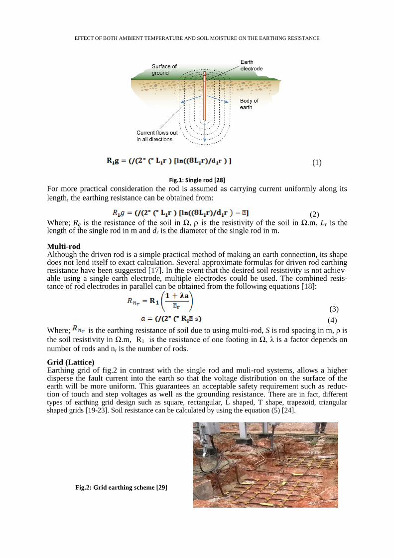
This work high light on the earthing parameters for a wide grounding dynamic range where all earthing electrodes (single rod, multi-rods and grids) can be used. Widest range of the temperature changes, as well as the excepted different soil types are considered. Grounding system calculations However, the high credibility of IEEE std-80 to calculate discretely the grounding resistance for different grounding topologies, the proposed calculations validate a complete resistance description in term of the whole grounding parameters. Summarized analytical calculations of the most dominant ground schemes are listed as follows: Single rod The single ground rod of fig.1, could offer the cheapest and most convenient means of instal-ling an electrode [4]. The following mathematical formulas [5-16] can be used to calculate the earthing resistance of a single driven rod in uniform soil having resistivity “ ”.
EFFECT OF BOTH AMBIENT TEMPERATURE AND SOIL MOISTURE ON THE EARTHING RESISTANCE
(1) .
Fig.1: Single rod [28]
For more practical consideration the rod is assumed as carrying current uniformly along its
length, the earthing resistance can be obtained from:
(2) Where; Rg is the resistance of the soil in Ω, is the resistivity of the soil in Ω.m, Lr is the length of the single rod in m and dr is the diameter of the single rod in m. Multi-rod Although the driven rod is a simple practical method of making an earth connection, its shape does not lend itself to exact calculation. Several approximate formulas for driven rod earthing resistance have been suggested [17]. In the event that the desired soil resistivity is not achiev-able using a single earth electrode, multiple electrodes could be used. The combined resis-tance of rod electrodes in parallel can be obtained from the following equations [18]:
(3)
(4)
Where; is the earthing resistance of soil due to using multi-rod, S is rod spacing in m, ρ is
the soil resistivity in Ω.m, R1 is the resistance of one footing in Ω, λ is a factor depends on
number of rods and nr is the number of rods.
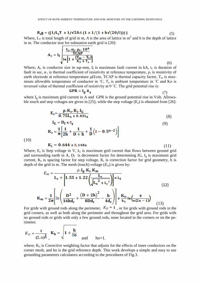
Grid (Lattice) Earthing grid of fig.2 in contrast with the single rod and muli-rod systems, allows a higher disperse the fault current into the earth so that the voltage distribution on the surface of the earth will be more uniform. This guarantees an acceptable safety requirement such as reduc-tion of touch and step voltages as well as the grounding resistance. There are in fact, different types of earthing grid design such as square, rectangular, L shaped, T shape, trapezoid, triangular shaped grids [19-23]. Soil resistance can be calculated by using the equation (5) [24].
Fig.2: Grid earthing scheme [29]
EFFECT OF BOTH AMBIENT TEMPERATURE AND SOIL MOISTURE ON THE EARTHING RESISTANCE
(5)
Where, LT is total length of grid in m, A is the area of lattice in m2 and h is the depth of lattice
in m. The conductor size for substation earth grid is [20]:
(6)
Where; Ac is conductor size in sqr-mm, If is maximum fault current in kA, tc is duration of
fault in sec, α r is thermal coefficient of resistivity at reference temperature, ρr is resistivity of
earth electrode at reference temperature μΩ/cm, TCAP is thermal capacity factor, Tm is max-
imum allowable temperature of conductor in ˚C, Ta is ambient temperature in ˚C and Ko is
reversed value of thermal coefficient of resistivity at 0 ˚C. The grid potential rise is:
(7)
where Ig is maximum grid current in A and GPR is the ground potential rise in Volt. Allowa-
ble touch and step voltages are given in [25]; while the step voltage (Es) is obtained from [26]:
(8)
(9)
(10)
(11) Where; Es is Step voltage in V, IG is maximum grid current that flows between ground grid
and surrounding earth in A, Df is decrement factor for determining IG, Ig is maximum grid
current, Ks is spacing factor for step voltage, Ki is correction factor for grid geometry, h is
depth of the grid in m. The mesh (touch) voltage (Em) is given by:
(12)
(13) For grids with ground rods along the perimeter, , or for grids with ground rods in the
grid corners, as well as both along the perimeter and throughout the grid area. For grids with
no ground rods or grids with only a few ground rods, none located in the corners or on the pe-
rimeter.
, and ho=1.
where; Kii is Corrective weighting factor that adjusts for the effects of inner conductors on the
corner mesh, and ho is the grid reference depth. This work develops a simple and easy to use
grounding parameters calculators according to the procedures of Fig.3.
EFFECT OF BOTH AMBIENT TEMPERATURE AND SOIL MOISTURE ON THE EARTHING RESISTANCE
(a) Grid earthing resistance (b) Earthing Parameters
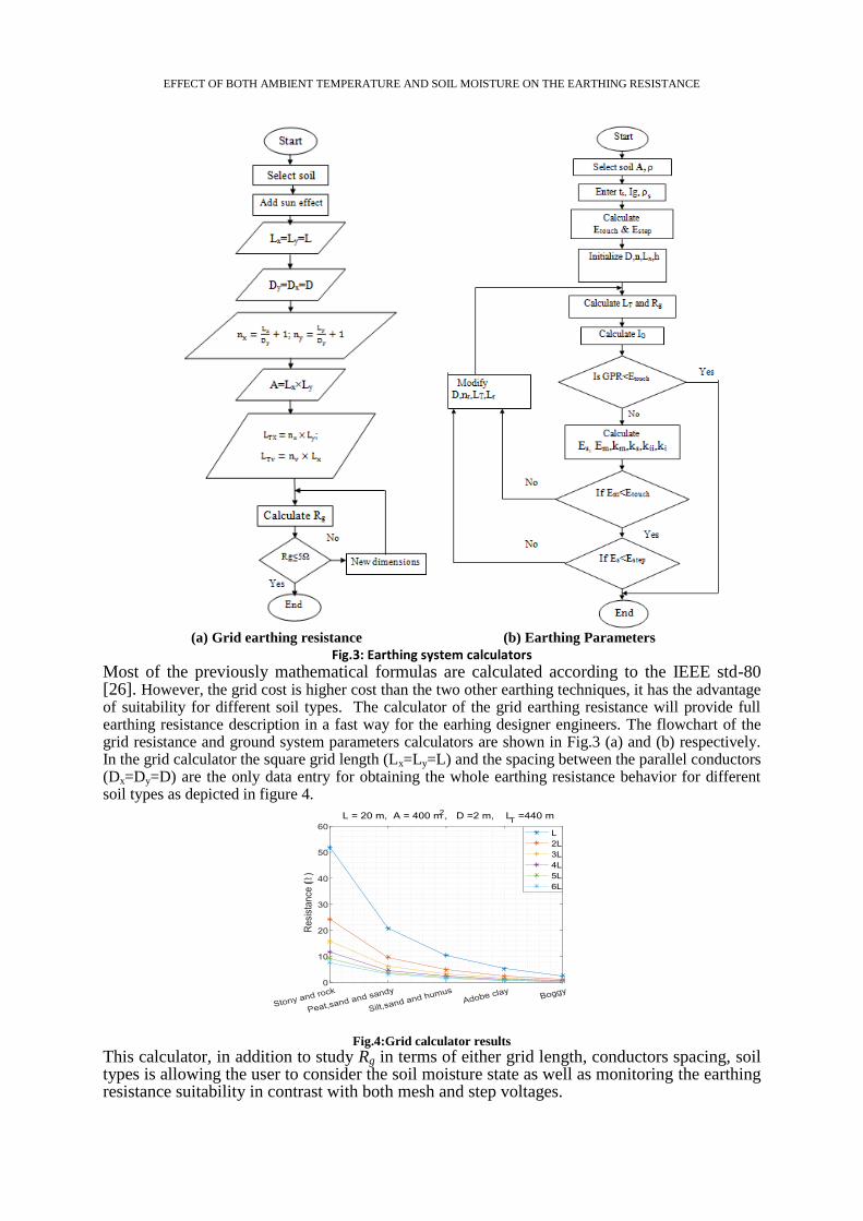
Fig.3: Earthing system calculators Most of the previously mathematical formulas are calculated according to the IEEE std-80 [26]. However, the grid cost is higher cost than the two other earthing techniques, it has the advantage of suitability for different soil types. The calculator of the grid earthing resistance will provide full earthing resistance description in a fast way for the earhing designer engineers. The flowchart of the grid resistance and ground system parameters calculators are shown in Fig.3 (a) and (b) respectively. In the grid calculator the square grid length (Lx=Ly=L) and the spacing between the parallel conductors (Dx=Dy=D) are the only data entry for obtaining the whole earthing resistance behavior for different soil types as depicted in figure 4.
Fig.4:Grid calculator results
This calculator, in addition to study Rg in terms of either grid length, conductors spacing, soil types is allowing the user to consider the soil moisture state as well as monitoring the earthing resistance suitability in contrast with both mesh and step voltages.
EFFECT OF BOTH AMBIENT TEMPERATURE AND SOIL MOISTURE ON THE EARTHING RESISTANCE
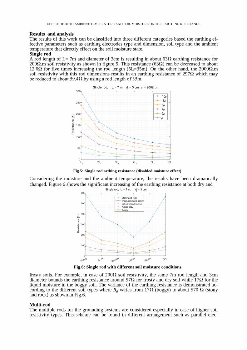
Results and analysis The results of this work can be classified into three different categories based the earthing ef-fective parameters such as earthing electrodes type and dimension, soil type and the ambient temperature that directly effect on the soil moisture state. Single rod A rod length of L= 7m and diameter of 3cm is resulting in about 63Ω earthing resistance for 200Ω.m soil resistivity as shown in figure 5. This resistance (63Ω) can be decreased to about 12.6Ω for five times increasing the rod length (5L=35m). On the other hand, the 2000Ω.m soil resistivity with this rod dimensions results in an earthing resistance of 297Ω which may be reduced to about 59.4Ω by using a rod length of 35m.
Fig.5: Single rod arthing resistance (disabled moisture effect)
Considering the moisture and the ambient temperature, the results have been dramatically
changed. Figure 6 shows the significant increasing of the earthing resistance at both dry and
Fig.6: Single rod with different soil moisture conditions
frosty soils. For example, in case of 200Ω soil resistivity, the same 7m rod length and 3cm diameter bounds the earthing resistance around 57Ω for frosty and dry soil while 17Ω for the liquid moisture in the boggy soil. The variance of the earthing resistance is demonstrated ac-cording to the different soil types where Rg varies from 17Ω (boggy) to about 570 Ω (stony and rock) as shown in Fig.6. Multi-rod The multiple rods for the grounding systems are considered especially in case of higher soil resistivity types. This scheme can be found in different arrangement such as parallel elec-
EFFECT OF BOTH AMBIENT TEMPERATURE AND SOIL MOISTURE ON THE EARTHING RESISTANCE
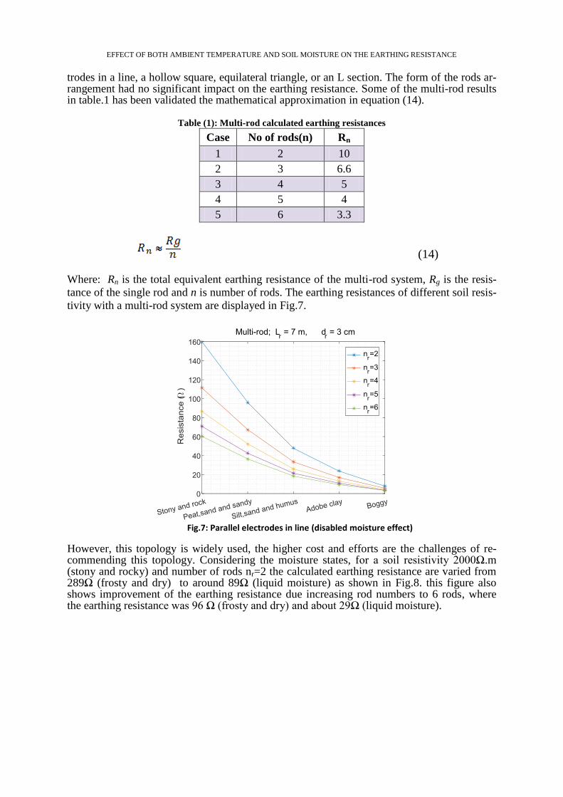
trodes in a line, a hollow square, equilateral triangle, or an L section. The form of the rods ar-rangement had no significant impact on the earthing resistance. Some of the multi-rod results in table.1 has been validated the mathematical approximation in equation (14).
Table (1): Multi-rod calculated earthing resistances
Case No of rods(n) Rn
1 2 10
2 3 6.6
3 4 5
4 5 4
5 6 3.3
(14)
Where: Rn is the total equivalent earthing resistance of the multi-rod system, Rg is the resis-
tance of the single rod and n is number of rods. The earthing resistances of different soil resis-
tivity with a multi-rod system are displayed in Fig.7.
Fig.7: Parallel electrodes in line (disabled moisture effect)
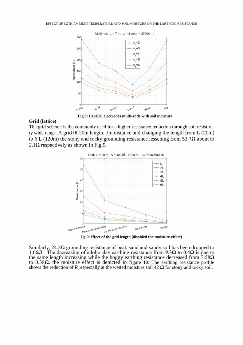
However, this topology is widely used, the higher cost and efforts are the challenges of re-commending this topology. Considering the moisture states, for a soil resistivity 2000Ω.m (stony and rocky) and number of rods nr=2 the calculated earthing resistance are varied from 289Ω (frosty and dry) to around 89Ω (liquid moisture) as shown in Fig.8. this figure also shows improvement of the earthing resistance due increasing rod numbers to 6 rods, where the earthing resistance was 96 Ω (frosty and dry) and about 29Ω (liquid moisture).
EFFECT OF BOTH AMBIENT TEMPERATURE AND SOIL MOISTURE ON THE EARTHING RESISTANCE
Fig.8: Parallel electrodes multi-rods with soil moisture
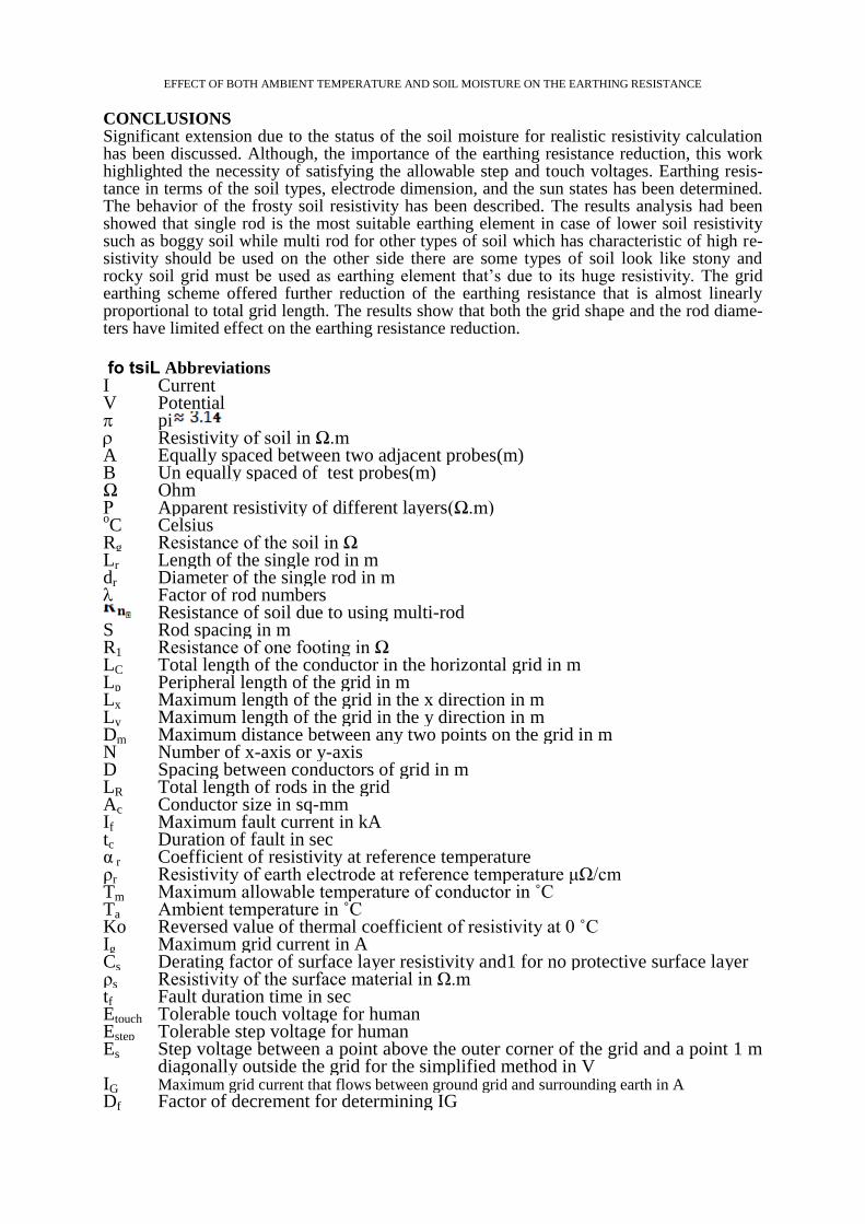
Grid (lattice)
The grid scheme is the commonly used for a higher resistance reduction through soil resistivi-
ty wide range. A grid 0f 20m length, 3m distance and changing the length from L (20m)
to 6 L (120m) the stony and rocky grounding resistance lessening from 53.7Ω about to
2.1Ω respectively as shown in Fig.9.
Fig.9: Effect of the grid length (disabled the moisture effect)
Similarly, 24.3Ω grounding resistance of peat, sand and sandy soil has been dropped to 1.06Ω. The decreasing of adobe clay earthing resistance from 9.3Ω to 0.4Ω is due to the same length increasing while the boggy earthing resistance decreased from 7.58Ω to 0.38Ω. the moisture effect is depicted in figure 10. The earthing resistance profile shows the reduction of Rg especially at the wetted moisture soil 42 Ω for stony and rocky soil.

EFFECT OF BOTH AMBIENT TEMPERATURE AND SOIL MOISTURE ON THE EARTHING RESISTANCE
Fig.10: Grid earthing system with moistured soil
Using 180 m grid length for instance can accomplish the permissible values of Rg for all dif-
ferent soil types at all moisture states except stony and rocky soil as obvious in the figure 11.
Fig.11: Rg of the 180 m grid length
One can add either the salts as improvement tools for these excepted soils or water tube. finally, the earthing resistances of the grid built-in rods 0, 5, 10 and 20 were 2.86, 2.89, 2.90, 2.92Ω respectively as listed in table 2. It is clear that the limited changes of the resis-tance and the step voltage while a significant touch voltage has been reached for zero built-in grid rods.
Table 2: Rods effect on the grid earthing parameters
No Built-
in rods
Touch vol-
tage (V)
Touch
allowable
Step
Voltage(V)
Step
Allowable(V)
GPR
(V) Rg(Ω)
1 0 1465 737 680 2454 5867 2.92
2 5 1208 737 643 2454 5827 2.90
3 10 1120 737 610 2454 5791 2.9
4 20 977 737 553 2454 5728 2.86
EFFECT OF BOTH AMBIENT TEMPERATURE AND SOIL MOISTURE ON THE EARTHING RESISTANCE
CONCLUSIONS Significant extension due to the status of the soil moisture for realistic resistivity calculation has been discussed. Although, the importance of the earthing resistance reduction, this work highlighted the necessity of satisfying the allowable step and touch voltages. Earthing resis-tance in terms of the soil types, electrode dimension, and the sun states has been determined. The behavior of the frosty soil resistivity has been described. The results analysis had been showed that single rod is the most suitable earthing element in case of lower soil resistivity such as boggy soil while multi rod for other types of soil which has characteristic of high re-sistivity should be used on the other side there are some types of soil look like stony and rocky soil grid must be used as earthing element that’s due to its huge resistivity. The grid earthing scheme offered further reduction of the earthing resistance that is almost linearly proportional to total grid length. The results show that both the grid shape and the rod diame-ters have limited effect on the earthing resistance reduction.
fo tsiL Abbreviations Current I Potential V pi Resistivity of soil in Ω.m Equally spaced between two adjacent probes(m) A Un equally spaced of test probes(m) B Ohm Ω Apparent resistivity of different layers(Ω.m) Ρ Celsius
oC
Resistance of the soil in Ω Rg Length of the single rod in m Lr Diameter of the single rod in m dr Factor of rod numbers Resistance of soil due to using multi-rod Rod spacing in m S Resistance of one footing in Ω R1 Total length of the conductor in the horizontal grid in m LC Peripheral length of the grid in m Lp Maximum length of the grid in the x direction in m Lx Maximum length of the grid in the y direction in m Ly Maximum distance between any two points on the grid in m Dm Number of x-axis or y-axis N Spacing between conductors of grid in m D Total length of rods in the grid LR Conductor size in sq-mm Ac Maximum fault current in kA If Duration of fault in sec tc Coefficient of resistivity at reference temperature α r Resistivity of earth electrode at reference temperature μΩ/cm ρr Maximum allowable temperature of conductor in ˚C Tm Ambient temperature in ˚C Ta Reversed value of thermal coefficient of resistivity at 0 ˚C Ko Maximum grid current in A Ig Derating factor of surface layer resistivity and1 for no protective surface layer Cs Resistivity of the surface material in Ω.m ρs Fault duration time in sec tf Tolerable touch voltage for human Etouch Tolerable step voltage for human Estep Step voltage between a point above the outer corner of the grid and a point 1 m diagonally outside the grid for the simplified method in V
Es
Maximum grid current that flows between ground grid and surrounding earth in A IG Factor of decrement for determining IG Df
EFFECT OF BOTH AMBIENT TEMPERATURE AND SOIL MOISTURE ON THE EARTHING RESISTANCE
Factor of spacing for step voltage simplified method Ks Factor of correction for grid geometry Ki Depth of the grid in m H Mesh voltage in V Em Factor of the corrective weighting that adjusts for effects of inner conductors on mesh corner, simplified method
Kii
Grid reference depth Ho Hemisphere radius and round plate radius in m a1 Diameter of ring in m dring Diameter of wire in m dwire
REFERENCES [1]. Tung, C. C., & Lim, S. C. (2017). Performance of Electrical Grounding System in Soil at
Low Moisture Content Condition at Various Compression Levels. Journal of Engineering Science and Technology, 12, 27-47.
[2]. Popović, L. M. (2018). Reduction of the fault current passing through the grounding system of an HV substation supplied by cable line. International Journal of Electrical Power & Ener-gy Systems, 99, 493-499.
[3]. Jha, V. K., & Kumar, R. (2018). Refocusing Electrical Safety Aspects & its Regulatory Re-quirement in Power Plant.
[4]. Androvitsaneas, V. P., Gonos, I. F., & Stathopulos, I. A. (2016). Experimental study on tran-sient impedance of grounding rods encased in ground enhancing compounds. Electric Power Systems Research, 139, 109-115.
[5]. Jovanović, D. B., Cvetković, N. N., Ristic, A. T., & Stanković, V. B. (2015, May). Different calculation methods and experimental validation for various ground electrode types. In Advanced Topics in Electrical Engineering (ATEE), 2015 9th International Symposium on (pp. 337-342). IEEE.
[6]. Dawalibi, F., & Mukhedkar, D. (1975). Optimum design of substation grounding in a two layer earth structure: Part IߞAnalytical study. IEEE Transactions on Power Apparatus and Sys-tems, 94(2), 252-261.
[7]. Melipoulos, A. P. S., Xia, F., Joy, E. B., & Cokkinides, G. J. (1993). An advanced computer model for grounding system analysis. IEEE Transactions on Power Delivery, 8(1), 13-23.
[8]. Chow, Y. L., & Salama, M. M. A. (1994). A simplified method for calculating the substation grounding grid resistance. IEEE Transactions on Power Delivery, 9(2), 736-742.
[9]. Sullivan, J. A. (1998). Alternative earthing calculations for grids and rods. IEE Proceedings-Generation, Transmission and Distribution, 145(3), 271-280.
[10]. Colominas, I., Navarrina, F., & Casteleiro, M. (2002). A numerical formulation for groun-ding analysis in stratified soils. IEEE Transactions on Power Delivery, 17(2), 587-595.
[11]. Bendito, E., Carmona, Á., Encinas, A. M., & Jimenez, M. J. (2004). The extremal charges method in grounding grid design. IEEE transactions on power delivery, 19(1), 118-123.
[12]. Guemes, J. A., & Hernando, F. E. (2004). Method for calculating the ground resistance of grounding grids using FEM. IEEE Transactions on Power Delivery, 19(2), 595-600.
[13]. Guemes-Alonso, J. A., Hernando-Fernández, F. E., Rodríguez-Bona, F., & Ruiz-Moll, J. M. (2006). A practical approach for determining the ground resistance of grounding grids. IEEE transactions on Power Delivery, 21(3), 1261-1266.
[14]. Cao, X., Wu, G., Zhou, W., & Li, R. (2008, November). New method for calculating ground resistance of grounding grids buried in horizon two-layer soil. In High Voltage Engi-neering and Application, 2008. ICHVE 2008. International Conference on (pp. 241-244). IEEE.
[15]. Ma, J., & Dawalibi, F. P. (2009). Computerized analysis of grounding plates in multilayer soils. IEEE Transactions on Power Delivery, 24(2), 650-655.
[16]. Melipoulos, A. P. S., Xia, F., Joy, E. B., & Cokkinides, G. J. (1993). An advanced com-puter model for grounding system analysis. IEEE Transactions on Power Delivery, 8(1), 13-23.
[17]. G. F. Tagg, Earth Resistances. London, U.K.: Newnes, 1964. [18]. BSI 7430 ,'' Code of practice for protective earthing of electrical installations'',2011,pp42 . [19]. Li, S. (2016). OLGGA: The OptimaL Ground Grid Application. Arizona State University.
EFFECT OF BOTH AMBIENT TEMPERATURE AND SOIL MOISTURE ON THE EARTHING RESISTANCE
[20]. Wai, H. N., & San Lwin, K. (2014). Design and Performance of Primary Substation Earth-
ing System (230/33 kV). [21]. Akshay Patil,'' Substation Earthing Design '', Jan. – Feb. 2017, IOSR-JEEE, PP 12-17. [22]. Balev, V., & Charan, P. (2014). Substation grounding optimization. [23]. Vyas, K. A., & Jamnani, J. G. (2012). Optimal Design of Grounding System for HV/EHV
Substations in Two Layered Soil. International Journal of Emerging Technology and Ad-vanced Engineering, 2(5).
[24]. Guo, D., Lathi, D., Harid, N., Griffiths, H., Haddad, A., & Ainsley, A. (2010, October). Experimental investigation into the performance of large-scale earthing electrodes. In High Voltage Engineering and Application (ICHVE), 2010 International Conference on (pp. 465-468). IEEE.
[25]. Prasad, D., & Sharma, H. C. (2011). Significance of Step and Touch Voltages. Interna-tional Journal of Soft Computing and Engineering (IJSCE) Volume-1, Issue, 193-197.
[26]. IEEE STD 80-2000. (2000). Guide for Safety in AC Substation Grounding. [27]. Gustafson, R. J., Pursley, R., & Albertson, V. D. (1990). Seasonal grounding resistance
variations on distribution systems. IEEE Transactions on Power Delivery, 5(2), 1013-1018. [28]. Online
https://www.wiley.com/legacy/wileychi/eca_wiringregulations/supp/Appendix_12.pdf. [29]. On line http://www.keywordsdoctor.com/ZWFydGggbWF0IGluc3RhbGxhdGlvbg/.