Embed Size (px)
Citation preview

HBRC Journal (2015) xxx, xxx–xxx
Housing and Building National Research Center
HBRC Journal
http://ees.elsevier.com/hbrcj
Effect of bond loss of tension reinforcement on
the flexural behaviour of reinforced concrete beams
Peer review under responsibility of Housing and Building National
Research Center.
Production and hosting by Elsevier
http://dx.doi.org/10.1016/j.hbrcj.2015.01.0031687-4048 ª 2015 Production and hosting by Elsevier B.V. on behalf of Housing and Building National Research Center.This is an open access article under the CC BY-NC-ND license (http://creativecommons.org/licenses/by-nc-nd/4.0/).
Please cite this article in press as: M.I. Mousa, Effect of bond loss of tension reinforcement on the flexural behaviour of reinforced concrete beams, HBRC(2015), http://dx.doi.org/10.1016/j.hbrcj.2015.01.003
Magda I. Mousa
Structural Engineering Department, Faculty of Eng. El-Mansoura University, Egypt
Received 5 November 2014; revised 22 December 2014; accepted 8 January 2015
KEYWORDS
Beams;
Reinforced concrete;
Bond loss;
Flexure;
Ultimate load;
Deflection
Abstract An experimental programme has been conducted in order to investigate the flexural
behaviour of concrete beams with variable un-bonded length of tension reinforcement. A test series
of six simple beams containing different nominal length without bond close to the support had been
conducted in this investigation. The tested beams are of 2250 mm total span loaded at the middle
third with two equal concentrated loads. The bond loss had been introduced with plastic tubes sur-
rounding the longitudinal tension reinforcement leaving short bonded lengths over supports and at
positions of stirrups crossing the longitudinal reinforcement. The effect of reinforcement bond loss
on the response, cracking load, crack propagation, deflection, ultimate capacity, reinforcement
strain at mid span and mode of failure of beams is examined in this paper. The cracking load, num-
ber of cracks in the flexural zone, and the crack width are affected significantly with increasing the
area of bond loss. On the other hand, the reduction in the ultimate load capacity is surprisingly low
even with 73% loss of bond. This refers to the creation of high bond forces at the small bonding
areas at the crossing stirrups which compensates the high bonding loss in the longitudinal bars
between stirrups.ª 2015 Production and hosting by Elsevier B.V. on behalf of Housing and Building National Research
Center. This is an open access article under theCCBY-NC-ND license (http://creativecommons.org/licenses/
by-nc-nd/4.0/).
Introduction
The bond between the reinforcing steel and surrounding con-crete depends primarily on the contact area, the surface textureof reinforcing bars, bar diameter and concrete cover.
Therefore, it is expected that the shape, location, length, width
and propagation of cracks as well as the load carrying capacitybe affected by the un-bonded length of tensile reinforcement.
This un-bonded length may be caused by construction errors.Honeycombed concrete resulting from bad compaction andthe use of dry and rough formwork could remove the concrete
cover. Washout also affects the bond properties of reinforcingsteel bars embedded in underwater concrete [1]. Over andabove, bond-loss is closely related to deterioration of structure.
Corrosion of reinforcement, internal frost damage, and alkali-silica reaction are three deterioration mechanisms that have anegative influence on bond between concrete and reinforce-ment. Investigations had been conducted to explain the flexu-
ral strength, shear strength, and bond as function of corrosion
Journal

2 M.I. Mousa
intensity [2–8]. Different studies had been performed byresearchers to evaluate the effect of different degrees ofreinforcement corrosion on the bond degradation using the
pull-out test [6,9]. Review of literature showed that limitedwork on un-bonded length of reinforced concrete beams hasbeen carried out. Nevertheless there are many studies on
un-bonded post tension tendons prestressed beams [10–15].The purpose of this research is to study the effect of the
unbounded length of tensile reinforcement on the behaviour
and reduction of flexural capacity of concrete beams. The lossof bond had been artificially introduced in the longitudinalreinforcement close to the supports and with varied length.The objective of this paper was to provide better understanding
of the influence of loss of bond along the longitudinal tensionreinforcement on the flexural behaviour of beams.
Experimental programme
A test series of six beams had been designed in order to inves-tigate the influence of bond loss along the longitudinal
reinforcement close to the support, on the behaviour of thisseries under flexural static loading. The unbounded lengthwas accurately created using a plastic tube with inner diameter
slightly larger than the longitudinal reinforcement surroundedby these tubes. The ends of the plastic tubes were sealed withsilicon and also surrounded with plastic tape. This method
was chosen to simulate the unbounded length due to corro-sion. One reference beam (B0) was reinforced with two fullbonded longitudinal bars at the bottom and without stirrupsin order to examine the failure mode when compared with
another reference beam with stirrups (B1). The dimensions ofthe tested beams were 2250 mm length · 200 mmheight · 120 mm width. The six tested beams were simply sup-
ported and loaded with two equal point loads at the middlethird of the span. The bottom longitudinal reinforcementwas 2U16 and the upper was 2U10 with 15Ø6/2100 stirrups
as shown in Fig. 1a. For beams with stirrups the unboundedlength varied from two spaces between stirrups close to eachsupport, as in beam B2 to six spaces, beam B4. The bond is
available at all intersections between stirrups and longitudinal
(a) Dimension and deta
(b) Details of un-
Fig. 1 Concrete dimensions and details
Please cite this article in press as: M.I. Mousa, Effect of bond loss of tension reinfor(2015), http://dx.doi.org/10.1016/j.hbrcj.2015.01.003
reinforcement (�20 mm), Fig. 1b. The bottom reinforcementin all beams studied was straight except in beam B5 where ithad 90� hook at the end in order to develop better anchorage
of the longitudinal bars as shown in Fig. 2.
Material and concrete proportions
Portland cement (CEM I 42,5N) was used in preparing theconcrete mix of this programme. The fine aggregate used wasnatural siliceous sand with a fineness modulus of 2.6, specific
gravity 2.63 and unit weight of 1750 kg/m3, and the coarseaggregate was gravel of two sizes 10 mm and 20 mm. Thegrading of aggregates satisfied the requirements of the Egyptian
specifications [16]. The superplasticizer used was the sulphatednaphthalene formaldehyde condensate type. The used silicafume (SF) contains silica (SiO2) of 95% and was of 20% ofcementweight.The concretemix chosen for casting the test beams
was designed to be high strength concrete and its proportionsare presented in Table 1. The compressive strength (fcu) wastested for 150 mm cubes, the tensile strength (fsp) was
determined from splitting tension tests of 150 mm · 300 mmcylinders and the bond strength (fb) was calculated from pullout tests on cylinders of 150 mm · 300 mm size with central
ribbed bars of 16 mmdiameter. In all cases at least six specimenswere used. The following mean values were obtained:fcu = 67.32 MPa, fsp = 4.53 MPa, and fb = 8.97 MPa, Table 1.
For the reinforcement, three specimens were tested for
every bar diameter. The longitudinal reinforcement in tensionconsisted of two ribbed bars with diameter 16 mm at the bot-tom of the beam, with an average yield strength fy = 498 MPa.
The longitudinal compression reinforcement at the top of thebeam consisted of two ribbed bars of 10 mm diameter, withan average yield strength of 427 MPa. Plain round bars of
6 mm diameter were used as stirrups with spacing 150 mmand with average yield strength of 300 MPa.
Specimen preparation and test procedure
Six steel moulds were used for casting the specimens; they werestiff enough to prevent any significant movement during
ils of tested beam.
bonded zone.
of tested beam and un-bonded zone.
cement on the flexural behaviour of reinforced concrete beams, HBRC Journal
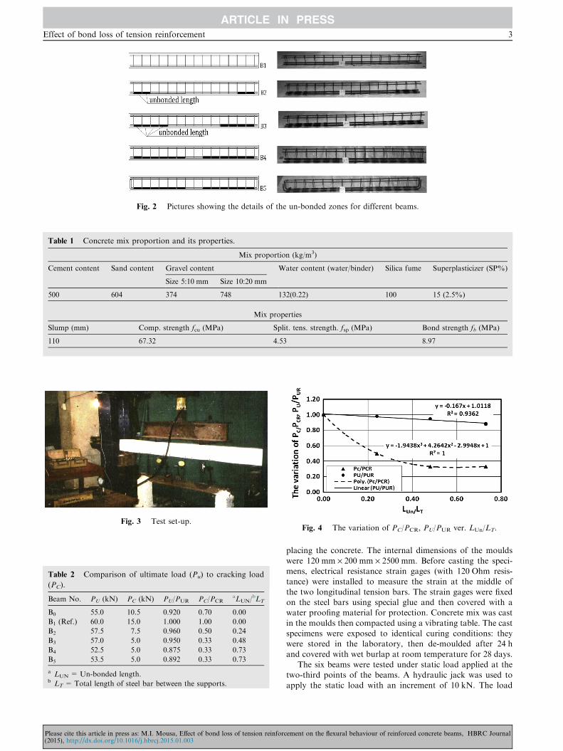
Fig. 2 Pictures showing the details of the un-bonded zones for different beams.
Table 1 Concrete mix proportion and its properties.
Mix proportion (kg/m3)
Cement content Sand content Gravel content Water content (water/binder) Silica fume Superplasticizer (SP%)
Size 5:10 mm Size 10:20 mm
500 604 374 748 132(0.22) 100 15 (2.5%)
Mix properties
Slump (mm) Comp. strength fcu (MPa) Split. tens. strength. fsp (MPa) Bond strength fb (MPa)
110 67.32 4.53 8.97
Fig. 3 Test set-up.
Table 2 Comparison of ultimate load (Pu) to cracking load
(PC).
Beam No. PU (kN) PC (kN) PU/PUR PC/PCRaLUN/
bLT
B0 55.0 10.5 0.920 0.70 0.00
B1 (Ref.) 60.0 15.0 1.000 1.00 0.00
B2 57.5 7.5 0.960 0.50 0.24
B3 57.0 5.0 0.950 0.33 0.48
B4 52.5 5.0 0.875 0.33 0.73
B5 53.5 5.0 0.892 0.33 0.73
a LUN = Un-bonded length.b LT =Total length of steel bar between the supports.
Fig. 4 The variation of PC/PCR, PU/PUR ver. LUn/LT.
Effect of bond loss of tension reinforcement 3
Please cite this article in press as: M.I. Mousa, Effect of bond loss of tension reinforc(2015), http://dx.doi.org/10.1016/j.hbrcj.2015.01.003
placing the concrete. The internal dimensions of the moulds
were 120 mm · 200 mm · 2500 mm. Before casting the speci-mens, electrical resistance strain gages (with 120 Ohm resis-tance) were installed to measure the strain at the middle of
the two longitudinal tension bars. The strain gages were fixedon the steel bars using special glue and then covered with awater proofing material for protection. Concrete mix was cast
in the moulds then compacted using a vibrating table. The castspecimens were exposed to identical curing conditions: theywere stored in the laboratory, then de-moulded after 24 hand covered with wet burlap at room temperature for 28 days.
The six beams were tested under static load applied at thetwo-third points of the beams. A hydraulic jack was used toapply the static load with an increment of 10 kN. The load
ement on the flexural behaviour of reinforced concrete beams, HBRC Journal

B4
(a)
B3
B2
B1
B5
(b)
B0
B1
B2
B3
B0
B4
Fig. 5 The crack pattern of different beams.
4 M.I. Mousa
was kept constant for about fifteen minutes during each incre-ment while the readings were being recorded. The test was ter-
minated when the compression zone in concrete was damagedor when the load falls to zero. Fig. 3 shows the generalarrangement of the test set-up for all beams.
The deflection at the middle and one-third of the span of
the beams was measured using three dial gages with 0.01 mmaccuracy. The width of the most obvious crack was recorded,and measured using a crack-width comparator.
Please cite this article in press as: M.I. Mousa, Effect of bond loss of tension reinfor(2015), http://dx.doi.org/10.1016/j.hbrcj.2015.01.003
Test results and discussion
Cracking and failure load
The cracking load was affected sharply in the beams with bondloss compared to the reference beam. The cracking load (PC)
reduced by about 50% in the beam with 24% bond loss ofits length and the reduction increased up to 67% in the beam
cement on the flexural behaviour of reinforced concrete beams, HBRC Journal
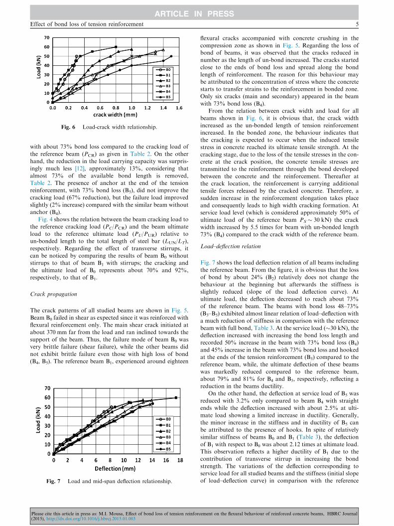
Fig. 6 Load-crack width relationship.
Effect of bond loss of tension reinforcement 5
with about 73% bond loss compared to the cracking load of
the reference beam (PCR) as given in Table 2. On the otherhand, the reduction in the load carrying capacity was surpris-ingly much less [12], approximately 13%, considering that
almost 73% of the available bond length is removed,Table 2. The presence of anchor at the end of the tensionreinforcement, with 73% bond loss (B5), did not improve thecracking load (67% reduction), but the failure load improved
slightly (2% increase) compared with the similar beam withoutanchor (B4).
Fig. 4 shows the relation between the beam cracking load to
the reference cracking load (PC/PCR) and the beam ultimateload to the reference ultimate load (PU/PUR) relative toun-bonded length to the total length of steel bar (LUN/LT),
respectively. Regarding the effect of transverse stirrups, itcan be noticed by comparing the results of beam B0 withoutstirrups to that of beam B1 with stirrups; the cracking andthe ultimate load of B0 represents about 70% and 92%,
respectively, to that of B1.
Crack propagation
The crack patterns of all studied beams are shown in Fig. 5.Beam B0 failed in shear as expected since it was reinforced withflexural reinforcement only. The main shear crack initiated at
about 370 mm far from the load and ran inclined towards thesupport of the beam. Thus, the failure mode of beam B0 wasvery brittle failure (shear failure), while the other beams did
not exhibit brittle failure even those with high loss of bond(B4, B5). The reference beam B1, experienced around eighteen
Fig. 7 Load and mid-span deflection relationship.
Please cite this article in press as: M.I. Mousa, Effect of bond loss of tension reinforc(2015), http://dx.doi.org/10.1016/j.hbrcj.2015.01.003
flexural cracks accompanied with concrete crushing in thecompression zone as shown in Fig. 5. Regarding the loss ofbond of beams, it was observed that the cracks reduced in
number as the length of un-bond increased. The cracks startedclose to the ends of bond loss and spread along the bondlength of reinforcement. The reason for this behaviour may
be attributed to the concentration of stress where the concretestarts to transfer strains to the reinforcement in bonded zone.Only six cracks (main and secondary) appeared in the beam
with 73% bond loss (B4).From the relation between crack width and load for all
beams shown in Fig. 6, it is obvious that, the crack widthincreased as the un-bonded length of tension reinforcement
increased. In the bonded zone, the behaviour indicates thatthe cracking is expected to occur when the induced tensilestress in concrete reached its ultimate tensile strength. At the
cracking stage, due to the loss of the tensile stresses in the con-crete at the crack position, the concrete tensile stresses aretransmitted to the reinforcement through the bond developed
between the concrete and the reinforcement. Thereafter atthe crack location, the reinforcement is carrying additionaltensile forces released by the cracked concrete. Therefore, a
sudden increase in the reinforcement elongation takes placeand consequently leads to high width cracking formation. Atservice load level (which is considered approximately 50% ofultimate load of the reference beam PS � 30 kN) the crack
width increased by 5.5 times for beam with un-bonded length73% (B4) compared to the crack width of the reference beam.
Load–deflection relation
Fig. 7 shows the load deflection relation of all beams includingthe reference beam. From the figure, it is obvious that the loss
of bond by about 24% (B2) relatively does not change thebehaviour at the beginning but afterwards the stiffness isslightly reduced (slope of the load deflection curve). At
ultimate load, the deflection decreased to reach about 73%of the reference beam. The beams with bond loss 48–73%(B3–B5) exhibited almost linear relation of load–deflection witha much reduction of stiffness in comparison with the reference
beam with full bond, Table 3. At the service load (�30 kN), thedeflection increased with increasing the bond loss length andrecorded 50% increase in the beam with 73% bond loss (B4)
and 45% increase in the beam with 73% bond loss and hookedat the ends of the tension reinforcement (B5) compared to thereference beam, while, the ultimate deflection of these beams
was markedly reduced compared to the reference beam,about 79% and 81% for B4 and B5, respectively, reflecting areduction in the beams ductility.
On the other hand, the deflection at service load of B5 was
reduced with 3.2% only compared to beam B4 with straightends while the deflection increased with about 2.5% at ulti-mate load showing a limited increase in ductility. Generally,
the minor increase in the stiffness and in ductility of B5 canbe attributed to the presence of hooks. In spite of relativelysimilar stiffness of beams B0 and B1 (Table 3), the deflection
of B1 with respect to B0 was about 2.12 times at ultimate load.This observation reflects a higher ductility of B1 due to thecontribution of transverse stirrup in increasing the bond
strength. The variations of the deflection corresponding toservice load for all studied beams and the stiffness (initial slopeof load–deflection curve) in comparison with the reference
ement on the flexural behaviour of reinforced concrete beams, HBRC Journal

Table 3 Variation of different measurements relative to the reference beam.
Beam No. Deflection (D)a Strain of steel bar (eS)a Crack width (CW)a Stiffness ratio
DS (mm) (DS/DSR) eS · 103 (eS/eSR) CW (mm) (CW/CWR) (S/SR)
B0 4.99 1.03 1.270 0.82 0.20 2.0 0.98
B1(Ref.) 4.83 1.00 1.545 1.00 0.10 0.0 1.00
B2 5.31 1.10 1.265 0.82 0.40 4.0 0.96
B3 6.71 1.39 1.356 0.88 0.50 5.0 0.84
B4 7.23 1.50 1.230 0.80 0.55 5.5 0.78
B5 7.00 1.45 1.835 1.19 0.70 7.0 0.79
R: refer to the reference beam.a The value at service load.
Fig. 8 Load-tension reinforcement strain relationship.
6 M.I. Mousa
beam are listed in Table 3. The maximum reduction in stiffnesswas about 22% for the beam with 73% loss in bond (B4).
Steel strain of the main steel
The tension steel of B3 and B4 did not reach the yield strain
while in B1, B2, and B5 the main bars yielded sufficiently, morethan twice the yield strain. At service load the strain of thebeam with un-bonded length of 73% (B4) was reduced by
about 20% relative to that of the reference beam (B1),Table 3. On the other hand, in the beam with 73% un-bondedlength and anchor at main steel ends (B5), the strain increasedby about 50% compared to the beam without anchor at the
ends (B4) and arrived to about 86% of the reference beam atultimate load.
Fig. 8 illustrates the relationship between the applied load
and the corresponding strain in the main steel of the testedbeams at the mid-span. Increasing the un-bonded length ofthe main reinforcement, leads to a reduction in the flexural
capacity of the beamwhich consequently causes a redistributionof internal stresses; hence, the recorded strain at mid-span ofsteel is reduced.
Conclusions
An experimental investigation was conducted in order to study
the behaviour of reinforced concrete beams with differentdegrees of bond loss in the longitudinal tension reinforcement.The results were compared with their reference beam with fullbond along the tension steel. From the results presented and
discussed in this paper, the following conclusions can be drawn.
Please cite this article in press as: M.I. Mousa, Effect of bond loss of tension reinfor(2015), http://dx.doi.org/10.1016/j.hbrcj.2015.01.003
1. The cracking load was significantly reduced with about50% in the beam with 24% un-bonded length in compar-ison with the reference beam. This reduction increased to67% when the un-bonded length increased to 73%.
2. A moderate reduction in the load carrying capacity wasobserved even in beams with significant bond loss; thereduction was only about 13% in the beam with 73% bond
loss of length. This observation may be attributed to thepresence of small areas of bond of the crossing stirrupswhich compensates for the loss of bond and creates high
bond forces.3. The predominant mode of failure of tested beams is flexural
failure except in the beam without stirrups, which exhibited
shear failure. The cracks, to a large extent, appeared only inthe bonded zone of the tension reinforcement.
4. Generally, increasing the un-bonded length along thetensile steel reinforcement reduces the number of cracks
and at the same time increases the width of cracks.5. The deflection of beams with loss of bond is in general
higher than that of the reference beam with full bond at
the same load reflecting lower stiffness. With increasingthe degree of bond loss, the deflection of beams increased;the loss of bond by about 73% increased the deflection
by 50% at service load compared to the reference beam.All the beams with bond-loss showed lower ductility thanthe reference beam (the ultimate deflection decreased).
6. The mid-span strain of the main steel decreased for the
beams with un-bonded length compared to the beam withfull bond. The exception was in the beam with anchor atits ends which showed significant strain increase in compar-
ison with the beam without anchor (2.3 times) and wasabout 93% of the reference beam with full bond.
7. The comparison of the findings of the beam B0 (without
stirrups) and B1 (with stirrups) produces the important roleof the transverse stirrups in achieving flexural and ductilefailure of B1 instead of shear failure of B0. The significant
increase in cracking load, ultimate load, ultimate deflection,and tension steel strain, besides smaller crack width of B1
relative to B0 is due to the increase in bond strength dueto the attribution of the stirrups.
Acknowledgment
The author gratefully acknowledges the support provided bythe Department of Civil Engineering, Structural engineering,
cement on the flexural behaviour of reinforced concrete beams, HBRC Journal

Effect of bond loss of tension reinforcement 7
at El-Mansoura University in particular, as well as the
concrete and material laboratories to carry out this work.Moreover, the author greatly thanks to prof. Dr. SalahEl-Metwally for his assistance in proof reading the paper.
References
[1] J.A. Joseph, A.I. Camille, Effect of washout Loss on bond
behaviour of steel embedded in underwater concrete, ACI
Struct. J. 110 (3) (2013) 511–519.
[2] P.S. Mangat, M.S. Elgarf, Flexural strength of concrete beams
with corroding reinforcement, ACI Struct. J. 96 (1999) 149–158.
[3] Y. Haken, E. Oygur, S. Serhan, An experimental study on the
bond strength between reinforcement bars and concrete cover,
strength and corrosion levels, Cem. Concr. Res. 34 (11) (2012)
2159–2167.
[4] C. Fang, K. Lundgren, L. Chen, C. Zhu, Corrosion influence on
bond in reinforced concrete, Cem. Concr. Res. 34 (11) (2004)
2159–2167.
[5] L. Chung, J.-H.j. Kim, S.-T. Yi, Bond strength predication for
reinforced concrete members with highly corroded
reinforcement bars, Cem. Concr. Compos. 30 (7) (2008) 606–
611.
[6] C. Fang, K. Lundgren, M. Plos, K. Gylltoft, Bond behaviour of
corroded reinforcing steel bars in concrete, Cem. Concr. Rese.
36 (10) (2006) 1931–1938.
[7] A.A. Almusallan, A.S. Al-Gahtani, A.R. Aziz, Rasheeduzzafar.
Effect of reinforcement corrosion on bond strength, Constr.
Build. Mater. 10 (2) (1996) 123–129.
Please cite this article in press as: M.I. Mousa, Effect of bond loss of tension reinforc(2015), http://dx.doi.org/10.1016/j.hbrcj.2015.01.003
[8] L. Amleh, S. Mirya, Corrosion influence on bond between steel
and concrete, ACI Struct. J. 96 (3) (1999) 415–423.
[9] F. Li, Y. Yuan, Effects of corrosion on bond behaviour between
steel strand and concrete, Constr. Build. Mater. 38 (2013) 413–
422.
[10] D. Coronelli, Corrosion cracking and bond strength modelling
for corroded bars in reinforced concrete, ACI Struc. J. 99 (3)
(2002) 267–276.
[11] H.S. Lee, T. Noguchi, F. Tomosawa, Evaluation of the bond
properties between concrete and reinforcement as a function of
the degree of reinforcement corrosion, Cem. Concr. Res. 32
(2002) 1313–1318.
[12] J. Joakim, T. Sven, Behaviour of reinforced concrete beams with
loss of bond at longitudinal reinforcement, ASCE Struct. J. 129
(10) (2003) 1376–1383.
[13] J. Yamazaki, B.T. Kattula, A.H. Mahock, Comparative study
of prestressed concrete beams, with and without bond, ACI.
Proc. 68 (1971) 116–125.
[14] P.R. Chakrabati, T.P. Whang, W. Brown, K.M. Arsad, E.
Amezeua, Unbonded post-tensioning tendons and partially
prestressed beams, ACI Struct. J. 91 (5) (1994) 616–625.
[15] I.M. Zaki, H.R. Sami, R.Z. Ezz–Eldin, Transfer and
development lengths of carbon fibre reinforced polymers
presstressing reinforcement, ACI J. 96 (4) (1999) 594–602.
[16] E.S.S. 1109/2008, 2008, Egyptian Standard Specification for
Aggregates, Egypt.
ement on the flexural behaviour of reinforced concrete beams, HBRC Journal