Embed Size (px)
Citation preview
EFFECT OF BEARING BEHAVIOR ON THE DYNAMIC CHARACTERISTICS AND SEISMIC RESPONSE OF MULTI-SPAN
COMPLEX BRIDGES
Aman Mwafy1, Amr Elnashai2 and W-H. Yen3
Abstract
Starting from a typical bridge from the inventory of FHWA concept designs, comparative analyses are conducted to evaluate the influence of friction bearing models on the dynamic characteristics and predicted seismic response of multi-span bridges. Refined 3-dimensional idealizations of the selected nine-span bridge were assembled for assessment using two analysis platforms. Comprehensive analyses were conducted to estimate the dynamic characteristics and demands of the bridge components in the longitudinal and transverse directions. Contrary to the design assumption, it is concluded that the behavior is significantly and fundamentally affected by taking account of friction at bearings, especially with regard to forces. The study confirms that neglecting friction in design is non-conservative and may compromise safety of the structure.
Introduction
Highway bridges are essential in a modern transportation infrastructure system. The reliable assessment of these key network components is significant for improving the understanding of their seismic performance. Such studies reduce uncertainties with regard to seismic performance, assist in deciding whether the current and proposed design procedures are adequate and pave the way towards improvements in design to resist earthquakes. Although older structures have proven more susceptible to damage under severe earthquakes, modern bridges, particularly those with complex structural characteristics such as base-isolated multi-span curved structures, may also be vulnerable under strong ground motions.
It is clear that designing a structure to elastically resist a severe earthquake is
an uneconomical approach. Yielding may be allowed to occur in bridge piers provided that the stability of the structure is not compromised. Conventionally designed bridges employ elastomeric bearings between the superstructure and the substructure to accommodate thermal movements. Electrometric bearings with improved seismic performance can also act as isolation devices to dissipate energy. During the design of the bridge, a zero frictional resistance for movable bearings might be assumed with restrictions of movement on both sides. This approach may be non-conservative since the bearing, which have low friction at low displacement rates, generate higher friction values under seismic conditions. This value depends on the axial stress, velocity and temperature. It ranges from 5% to 10% for the
1 Post-Doctoral Research Scholar, University of Illinois at Urbana-Champaign, USA. 2 Willett Professor of Engineering, Director of Mid-America Earthquake Centre,
University of Illinois at Urbana-Champaign, USA. 3 Research Structural Engineer, Program Manager of Seismic Hazard Mitigation, FHWA, USA.
PTFE/stainless steel bearings at high velocities and normal temperature (e.g. Constantinou et al., 1990; Bondonet and Filiatrault, 1997; Priestley et al., 1996). Therefore, it is important to investigate the approach used in design and compare its behavior with a more practical analytical model to assess the consequences of this assumption.
The primary objective of this paper is to present results of the first phase of a
comprehensive study carried out to assess the vulnerability of newly constructed complex bridges designed to the AASHTO specifications (AASHTO Division I and Division I-A, 1993-1995). The focus of this paper is on the impact of various bearing model options on the dynamic characteristics and seismic response of multi-span bridges. The investigation is conducted on a nine-span bridge selected by FHWA as a case study to represent a US typical design of complex highway bridges. Refined 3-dimensional modeling approaches are employed to realistically idealize the entire structure and its foundation for elastic and inelastic analyses. The modeling approach is examined and the effect of bearing behavior on dynamic characteristics and inelastic seismic demand is investigated by comparisons between results of different modeling approaches.
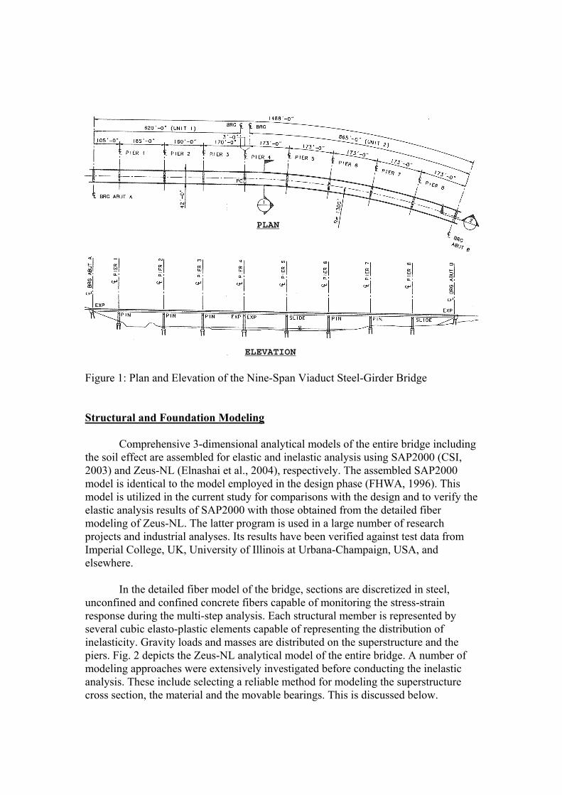
The Nine-Span Viaduct Steel-Girder Bridge
Fig. 1 shows the 1488 feet nine-span bridge. It is to be constructed across a large river and flood plain in a medium seismicity region (seismic performance category B) with a PGA of 0.15g. The structure consists of two units separated by an expansion joint: a four-span tangent unit and a five-span curved one with a 1300-foot radius. While the two units act independently in the longitudinal direction, they are linked in transverse deformation at the intermediate expansion joint and pivoting at the abutments. The superstructure is composed of four steel girders with a composite cast-in-place concrete deck. The seat-type abutments and the single-column intermediate piers are all cast-in-place. The piers and the abutments are supported on steel H-piles. Because the bridge crosses the main channel of a wide river, flow and ice loading dictated the size of the RC piers. The design of the bridge confirms with the AASHTO specifications (AASHTO Division I and Division I-A, 1993-1995). The subsoil is coarse alluvial flood deposits (very dense sand and gravel) for a depth of 50 feet overlying volcaniclastic sediments. Further structural detailing and geotechnical information are provided elsewhere (FHWA, 1996).
Various types of supports were employed in design including seat abutments as well as intermediate pinned and sliding bearings. Conventional pinned bearings at Piers 1, 2, 3, 6 and 7 (refer to Fig. 1 and 2(a)) were assumed to resist the entire seismic forces in the longitudinal direction. The bearings at the abutments, the expansion joint and at Piers 5 and 8 are sliding supports providing restraint in the transverse direction only. Hence, they accommodate significant motion in the longitudinal direction. Elastomeric bearings, such as PTFE, with a stainless steel sliding surface were employed in the design for the movable bearings. The transverse resistance is provided via girder stops capable of transferring transverse forces to the abutments and Piers 4, 5 and 8.
PLAN
ELEVATION
Figure 1: Plan and Elevation of the Nine-Span Viaduct Steel-Girder Bridge Structural and Foundation Modeling
Comprehensive 3-dimensional analytical models of the entire bridge including the soil effect are assembled for elastic and inelastic analysis using SAP2000 (CSI, 2003) and Zeus-NL (Elnashai et al., 2004), respectively. The assembled SAP2000 model is identical to the model employed in the design phase (FHWA, 1996). This model is utilized in the current study for comparisons with the design and to verify the elastic analysis results of SAP2000 with those obtained from the detailed fiber modeling of Zeus-NL. The latter program is used in a large number of research projects and industrial analyses. Its results have been verified against test data from Imperial College, UK, University of Illinois at Urbana-Champaign, USA, and elsewhere.
In the detailed fiber model of the bridge, sections are discretized in steel, unconfined and confined concrete fibers capable of monitoring the stress-strain response during the multi-step analysis. Each structural member is represented by several cubic elasto-plastic elements capable of representing the distribution of inelasticity. Gravity loads and masses are distributed on the superstructure and the piers. Fig. 2 depicts the Zeus-NL analytical model of the entire bridge. A number of modeling approaches were extensively investigated before conducting the inelastic analysis. These include selecting a reliable method for modeling the superstructure cross section, the material and the movable bearings. This is discussed below.
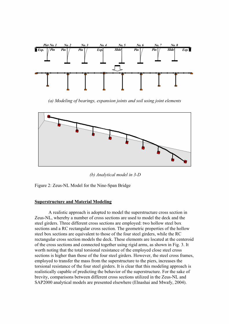
Pier No. 1 No. 2 No. 3 No. 4 No. 5 No. 6 No. 7 No. 8PinPin Exp. Pin PinSlidePin Slide Exp.Exp.
(a) Modeling of bearings, expansion joints and soil using joint elements
(b) Analytical model in 3-D
Figure 2: Zeus-NL Model for the Nine-Span Bridge Superstructure and Material Modeling
A realistic approach is adopted to model the superstructure cross section in Zeus-NL, whereby a number of cross sections are used to model the deck and the steel girders. Three different cross sections are employed: two hollow steel box sections and a RC rectangular cross section. The geometric properties of the hollow steel box sections are equivalent to those of the four steel girders, while the RC rectangular cross section models the deck. These elements are located at the centeroid of the cross sections and connected together using rigid arms, as shown in Fig. 3. It worth noting that the total torsional resistance of the employed close steel cross sections is higher than those of the four steel girders. However, the steel cross frames, employed to transfer the mass from the superstructure to the piers, increases the torsional resistance of the four steel girders. It is clear that this modeling approach is realistically capable of predicting the behavior of the superstructure. For the sake of brevity, comparisons between different cross sections utilized in the Zeus-NL and SAP2000 analytical models are presented elsewhere (Elnashai and Mwafy, 2004).
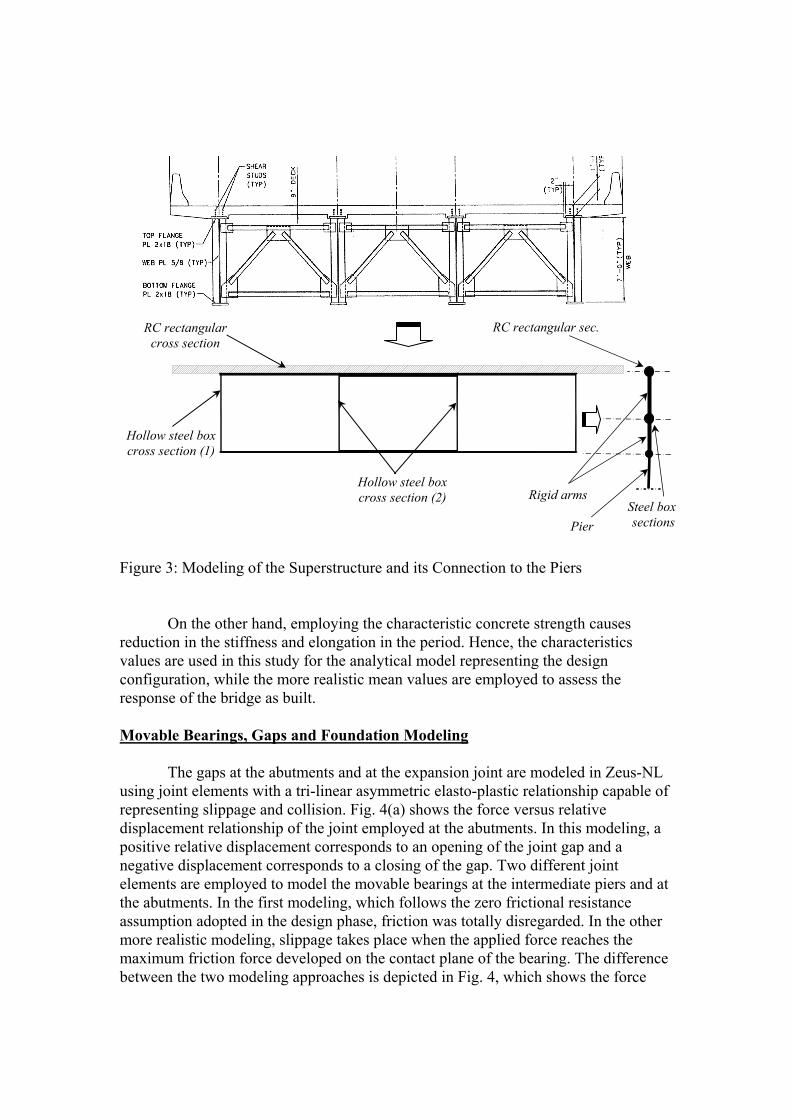
Hollow steel box
Figure 3: Modeling of the Superstructure and its Connection to the Piers
On the other hand, employing the characteristic concrete strength causes
reduction in the stiffness and elongation in the period. Hence, the characteristics values are used in this study for the analytical model representing the design configuration, while the more realistic mean values are employed to assess the response of the bridge as built. Movable Bearings, Gaps and Foundation Modeling
The gaps at the abutments and at the expansion joint are modeled in Zeus-NL
using joint elements with a tri-linear asymmetric elasto-plastic relationship capable of representing slippage and collision. Fig. 4(a) shows the force versus relative displacement relationship of the joint employed at the abutments. In this modeling, a positive relative displacement corresponds to an opening of the joint gap and a negative displacement corresponds to a closing of the gap. Two different joint elements are employed to model the movable bearings at the intermediate piers and at the abutments. In the first modeling, which follows the zero frictional resistance assumption adopted in the design phase, friction was totally disregarded. In the other more realistic modeling, slippage takes place when the applied force reaches the maximum friction force developed on the contact plane of the bearing. The difference between the two modeling approaches is depicted in Fig. 4, which shows the force
cross section (1)
Hollow steel box cross section (2)
RC rectangular cross section
Rigid arms
RC rectangular sec.
Steel box sections Pier
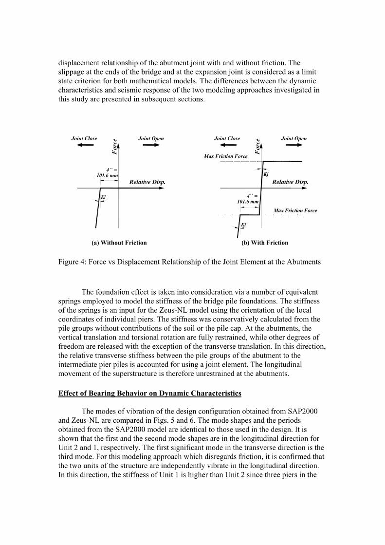
displacement relationship of the abutment joint with and without friction. The slippage at the ends of the bridge and at the expansion joint is considered as a limit state criterion for both mathematical models. The differences between the dynamic characteristics and seismic response of the two modeling approaches investigated in this study are presented in subsequent sections.
Relative Disp.
For
ce
101.6 mmRelative Disp.
For
ce
4`` =
Max Friction Force
Max Friction Force
(b) With Friction(a) Without Friction
Joint OpenJoint CloseJoint OpenJoint Close
Ki
Ki
Kj
101.6 mm4`` =
Figure 4: Force vs Displacement Relationship of the Joint Element at the Abutments
The foundation effect is taken into consideration via a number of equivalent springs employed to model the stiffness of the bridge pile foundations. The stiffness of the springs is an input for the Zeus-NL model using the orientation of the local coordinates of individual piers. The stiffness was conservatively calculated from the pile groups without contributions of the soil or the pile cap. At the abutments, the vertical translation and torsional rotation are fully restrained, while other degrees of freedom are released with the exception of the transverse translation. In this direction, the relative transverse stiffness between the pile groups of the abutment to the intermediate pier piles is accounted for using a joint element. The longitudinal movement of the superstructure is therefore unrestrained at the abutments. Effect of Bearing Behavior on Dynamic Characteristics
The modes of vibration of the design configuration obtained from SAP2000 and Zeus-NL are compared in Figs. 5 and 6. The mode shapes and the periods obtained from the SAP2000 model are identical to those used in the design. It is shown that the first and the second mode shapes are in the longitudinal direction for Unit 2 and 1, respectively. The first significant mode in the transverse direction is the third mode. For this modeling approach which disregards friction, it is confirmed that the two units of the structure are independently vibrate in the longitudinal direction. In this direction, the stiffness of Unit 1 is higher than Unit 2 since three piers in the
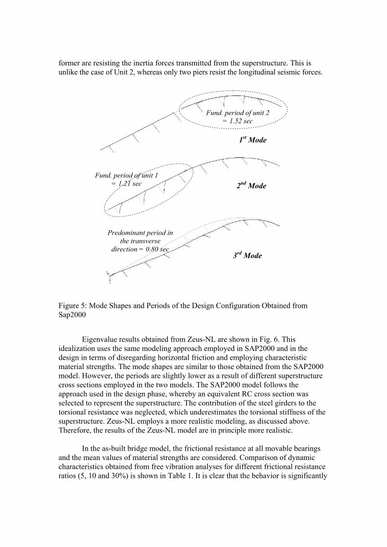
former are resisting the inertia forces transmitted from the superstructure. This is unlike the case of Unit 2, whereas only two piers resist the longitudinal seismic forces.
2nd Mode
1st Mode
Fund. period of unit 1 = 1.21 sec
Fund. period of unit 2 = 1.52 sec
Predominant period in the transverse
direction = 0.80 sec3rd Mode
Figure 5: Mode Shapes and Periods of the Design Configuration Obtained from Sap2000
Eigenvalue results obtained from Zeus-NL are shown in Fig. 6. This idealization uses the same modeling approach employed in SAP2000 and in the design in terms of disregarding horizontal friction and employing characteristic material strengths. The mode shapes are similar to those obtained from the SAP2000 model. However, the periods are slightly lower as a result of different superstructure cross sections employed in the two models. The SAP2000 model follows the approach used in the design phase, whereby an equivalent RC cross section was selected to represent the superstructure. The contribution of the steel girders to the torsional resistance was neglected, which underestimates the torsional stiffness of the superstructure. Zeus-NL employs a more realistic modeling, as discussed above. Therefore, the results of the Zeus-NL model are in principle more realistic.
In the as-built bridge model, the frictional resistance at all movable bearings
and the mean values of material strengths are considered. Comparison of dynamic characteristics obtained from free vibration analyses for different frictional resistance ratios (5, 10 and 30%) is shown in Table 1. It is clear that the behavior is significantly
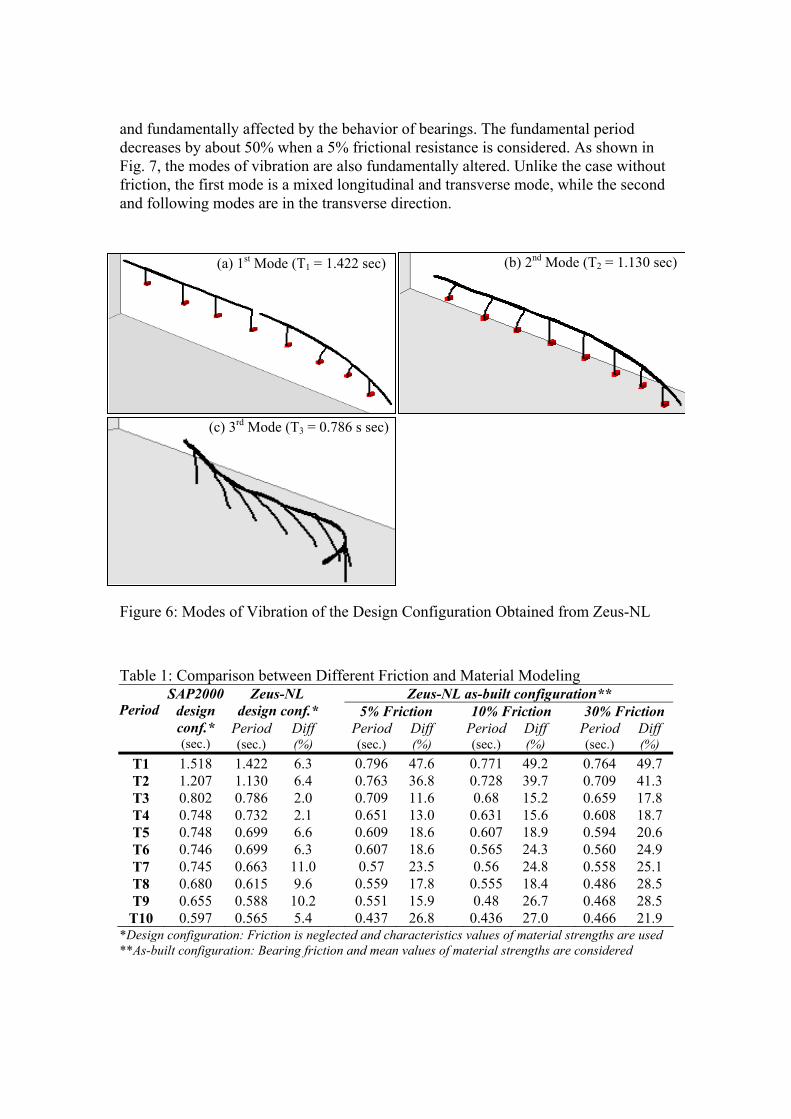
and fundamentally affected by the behavior of bearings. The fundamental period decreases by about 50% when a 5% frictional resistance is considered. As shown in Fig. 7, the modes of vibration are also fundamentally altered. Unlike the case without friction, the first mode is a mixed longitudinal and transverse mode, while the second and following modes are in the transverse direction.
(a) 1st Mode (T1 = 1.422 sec) (b) 2nd Mode (T2 = 1.130 sec)
(c) 3rd Mode (T3 = 0.786 s sec)
Figure 6: Modes of Vibration of the Design Configuration Obtained from Zeus-NL
Table 1: Comparison between Different Friction and Material Modeling
Zeus-NL as-built configuration** Zeus-NL design conf.* 5% Friction 10% Friction 30% Friction Period
SAP2000 design conf.* (sec.)
Period (sec.)
Diff (%) Period
(sec.) Diff (%) Period
(sec.) Diff (%) Period
(sec.) Diff (%)
T1 1.518 1.422 6.3 0.796 47.6 0.771 49.2 0.764 49.7 T2 1.207 1.130 6.4 0.763 36.8 0.728 39.7 0.709 41.3 T3 0.802 0.786 2.0 0.709 11.6 0.68 15.2 0.659 17.8 T4 0.748 0.732 2.1 0.651 13.0 0.631 15.6 0.608 18.7 T5 0.748 0.699 6.6 0.609 18.6 0.607 18.9 0.594 20.6 T6 0.746 0.699 6.3 0.607 18.6 0.565 24.3 0.560 24.9 T7 0.745 0.663 11.0 0.57 23.5 0.56 24.8 0.558 25.1 T8 0.680 0.615 9.6 0.559 17.8 0.555 18.4 0.486 28.5 T9 0.655 0.588 10.2 0.551 15.9 0.48 26.7 0.468 28.5
T10 0.597 0.565 5.4 0.437 26.8 0.436 27.0 0.466 21.9 *Design configuration: Friction is neglected and characteristics values of material strengths are used **As-built configuration: Bearing friction and mean values of material strengths are considered
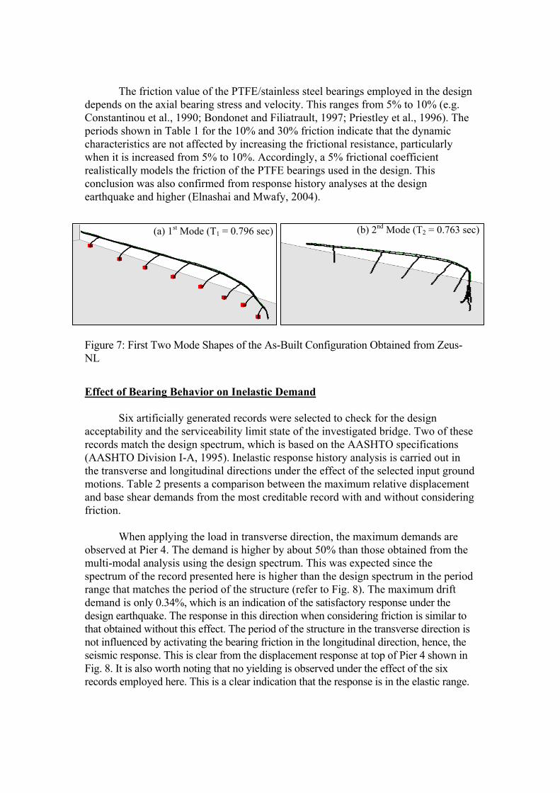
The friction value of the PTFE/stainless steel bearings employed in the design depends on the axial bearing stress and velocity. This ranges from 5% to 10% (e.g. Constantinou et al., 1990; Bondonet and Filiatrault, 1997; Priestley et al., 1996). The periods shown in Table 1 for the 10% and 30% friction indicate that the dynamic characteristics are not affected by increasing the frictional resistance, particularly when it is increased from 5% to 10%. Accordingly, a 5% frictional coefficient realistically models the friction of the PTFE bearings used in the design. This conclusion was also confirmed from response history analyses at the design earthquake and higher (Elnashai and Mwafy, 2004).
(b) 2nd Mode (T2 = 0.763 sec)
(a) 1st Mode (T1 = 0.796 sec)
Figure 7: First Two Mode Shapes of the As-Built Configuration Obtained from Zeus-NL
Effect of Bearing Behavior on Inelastic Demand
Six artificially generated records were selected to check for the design acceptability and the serviceability limit state of the investigated bridge. Two of these records match the design spectrum, which is based on the AASHTO specifications (AASHTO Division I-A, 1995). Inelastic response history analysis is carried out in the transverse and longitudinal directions under the effect of the selected input ground motions. Table 2 presents a comparison between the maximum relative displacement and base shear demands from the most creditable record with and without considering friction.
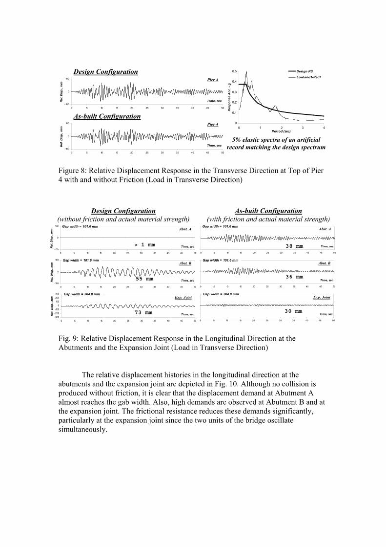
When applying the load in transverse direction, the maximum demands are observed at Pier 4. The demand is higher by about 50% than those obtained from the multi-modal analysis using the design spectrum. This was expected since the spectrum of the record presented here is higher than the design spectrum in the period range that matches the period of the structure (refer to Fig. 8). The maximum drift demand is only 0.34%, which is an indication of the satisfactory response under the design earthquake. The response in this direction when considering friction is similar to that obtained without this effect. The period of the structure in the transverse direction is not influenced by activating the bearing friction in the longitudinal direction, hence, the seismic response. This is clear from the displacement response at top of Pier 4 shown in Fig. 8. It is also worth noting that no yielding is observed under the effect of the six records employed here. This is a clear indication that the response is in the elastic range.
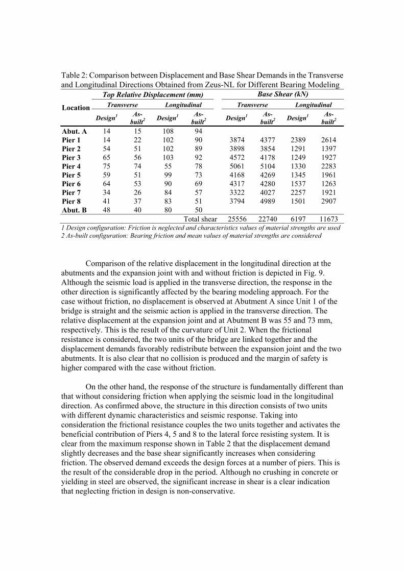
Table 2: Comparison between Displacement and Base Shear Demands in the Transverse and Longitudinal Directions Obtained from Zeus-NL for Different Bearing Modeling
Top Relative Displacement (mm) Base Shear (kN) Transverse Longitudinal Transverse Longitudinal Location
Design1 As-built2 Design1 As-
built2 Design1 As-built2 Design1 As-
built2
Abut. A 14 15 108 94 Pier 1 14 22 102 90 3874 4377 2389 2614 Pier 2 54 51 102 89 3898 3854 1291 1397 Pier 3 65 56 103 92 4572 4178 1249 1927 Pier 4 75 74 55 78 5061 5104 1330 2283 Pier 5 59 51 99 73 4168 4269 1345 1961 Pier 6 64 53 90 69 4317 4280 1537 1263 Pier 7 34 26 84 57 3322 4027 2257 1921 Pier 8 41 37 83 51 3794 4989 1501 2907 Abut. B 48 40 80 50
Total shear 25556 22740 6197 11673 1 Design configuration: Friction is neglected and characteristics values of material strengths are used 2 As-built configuration: Bearing friction and mean values of material strengths are considered
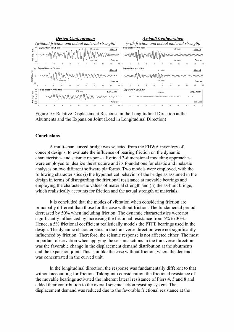
Comparison of the relative displacement in the longitudinal direction at the abutments and the expansion joint with and without friction is depicted in Fig. 9. Although the seismic load is applied in the transverse direction, the response in the other direction is significantly affected by the bearing modeling approach. For the case without friction, no displacement is observed at Abutment A since Unit 1 of the bridge is straight and the seismic action is applied in the transverse direction. The relative displacement at the expansion joint and at Abutment B was 55 and 73 mm, respectively. This is the result of the curvature of Unit 2. When the frictional resistance is considered, the two units of the bridge are linked together and the displacement demands favorably redistribute between the expansion joint and the two abutments. It is also clear that no collision is produced and the margin of safety is higher compared with the case without friction.
On the other hand, the response of the structure is fundamentally different than that without considering friction when applying the seismic load in the longitudinal direction. As confirmed above, the structure in this direction consists of two units with different dynamic characteristics and seismic response. Taking into consideration the frictional resistance couples the two units together and activates the beneficial contribution of Piers 4, 5 and 8 to the lateral force resisting system. It is clear from the maximum response shown in Table 2 that the displacement demand slightly decreases and the base shear significantly increases when considering friction. The observed demand exceeds the design forces at a number of piers. This is the result of the considerable drop in the period. Although no crushing in concrete or yielding in steel are observed, the significant increase in shear is a clear indication that neglecting friction in design is non-conservative.
Design Configuration
-100
0
100
0 5 10 15 20 25 30 35 40 45 50
Time, secRel
. Dis
p., m
m
Pier 4
As-built Configuration
-100
0
100
0 5 10 15 20 25 30 35 40 45 50
Time, secRel
. Dis
p., m
m
Pier 4 0
0.1
0.2
0.3
0.4
0.5
0 1 2 3 4Period (sec)
Res
pons
e A
cc. -
g
Design RS
Lowland1-Rec1
5% elastic spectra of an artificial record matching the design spectrum
Figure 8: Relative Displacement Response in the Transverse Direction at Top of Pier 4 with and without Friction (Load in Transverse Direction)
Design Configuration (without friction and actual material strength)
-100
0
100
0 5 10 15 20 25 30 35 40 45 50
Time, secRel
. Dis
p., m
m Abut. AGap width = 101.6 mm
As-built Configuration (with friction and actual material strength)
0 5 10 15 20 25 30 35 40 45 50
Time, sec
Abut. AGap width = 101.6 mm
-100
0
100
0 5 10 15 20 25 30 35 40 45 50
Time, secRel
. Dis
p., m
m Abut. BGap width = 101.6 mm
0 5 10 15 20 25 30 35 40 45 50
Time, sec
Abut. BGap width = 101.6 mm
-300
-200
-100
0
100
200
300
0 5 10 15 20 25 30 35 40 45 50
Time, secRel
. Dis
p., m
m Exp. JointGap width = 304.8 mm
0 5 10 15 20 25 30 35 40 45 50
Time, sec
Exp. JointGap width = 304.8 mm
> 1 mm 38 mm
36 mm 55 mm
30 mm 73 mm
Fig. 9: Relative Displacement Response in the Longitudinal Direction at the Abutments and the Expansion Joint (Load in Transverse Direction)
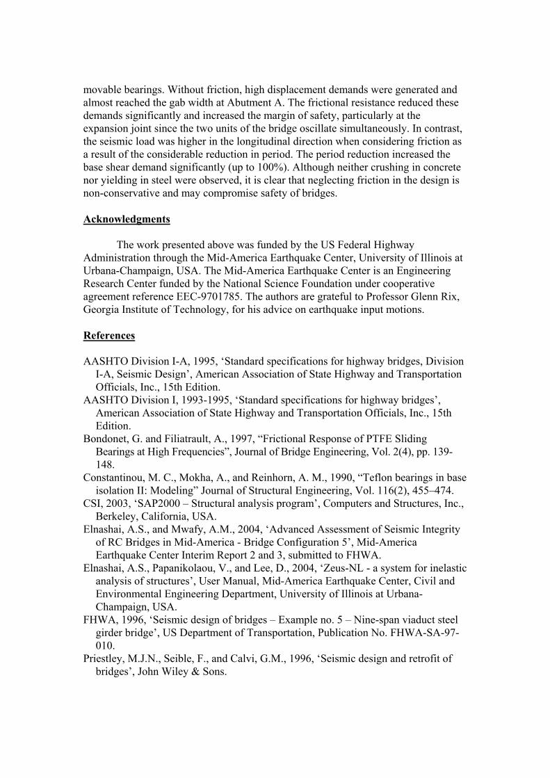
The relative displacement histories in the longitudinal direction at the abutments and the expansion joint are depicted in Fig. 10. Although no collision is produced without friction, it is clear that the displacement demand at Abutment A almost reaches the gab width. Also, high demands are observed at Abutment B and at the expansion joint. The frictional resistance reduces these demands significantly, particularly at the expansion joint since the two units of the bridge oscillate simultaneously.
Design Configuration (without friction and actual material strength)
-110
0
110
0 5 10 15 20 25 30 35 40 45 50
Time, secRel
. Dis
p., m
m Abut. AGap width = 101.6 mm
108 mm
101.4 mm
As-built Configuration (with friction and actual material strength)
0 5 10 15 20 25 30 35 40 45 50
Time, sec
Abut. AGap width = 101.6 mm
94 mm
79 mm
-110
0
110
0 5 10 15 20 25 30 35 40 45 50
Time, secRel
. Dis
p., m
m Abut. BGap width = 101.6 mm
80 mm
0 5 10 15 20 25 30 35 40 45 50
Time, sec
Abut. BGap width = 101.6 mm
50 mm
43 mm
-300
-200
-100
0
100
200
300
0 5 10 15 20 25 30 35 40 45 50
Time, secRel
. Dis
p., m
m Exp. JointGap width = 304.8 mm
152 mm
0 5 10 15 20 25 30 35 40 45 50
Time, sec
Exp. JointGap width = 304.8 mm
30 mm
Figure 10: Relative Displacement Response in the Longitudinal Direction at the Abutments and the Expansion Joint (Load in Longitudinal Direction) Conclusions
A multi-span curved bridge was selected from the FHWA inventory of concept designs, to evaluate the influence of bearing friction on the dynamic characteristics and seismic response. Refined 3-dimensional modeling approaches were employed to idealize the structure and its foundations for elastic and inelastic analyses on two different software platforms. Two models were employed, with the following characteristics (i) the hypothetical behavior of the bridge as assumed in the design in terms of disregarding the frictional resistance at movable bearings and employing the characteristic values of material strength and (ii) the as-built bridge, which realistically accounts for friction and the actual strength of materials.
It is concluded that the modes of vibration when considering friction are principally different than those for the case without friction. The fundamental period decreased by 50% when including friction. The dynamic characteristics were not significantly influenced by increasing the frictional resistance from 5% to 30%. Hence, a 5% frictional coefficient realistically models the PTFE bearings used in the design. The dynamic characteristics in the transverse direction were not significantly influenced by friction. Therefore, the seismic response is not affected either. The most important observation when applying the seismic actions in the transverse direction was the favorable change in the displacement demand distribution at the abutments and the expansion joint. This is unlike the case without friction, where the demand was concentrated in the curved unit.
In the longitudinal direction, the response was fundamentally different to that without accounting for friction. Taking into consideration the frictional resistance of the movable bearings activated the inherent lateral resistance of Piers 4, 5 and 8 and added their contribution to the overall seismic action resisting system. The displacement demand was reduced due to the favorable frictional resistance at the
movable bearings. Without friction, high displacement demands were generated and almost reached the gab width at Abutment A. The frictional resistance reduced these demands significantly and increased the margin of safety, particularly at the expansion joint since the two units of the bridge oscillate simultaneously. In contrast, the seismic load was higher in the longitudinal direction when considering friction as a result of the considerable reduction in period. The period reduction increased the base shear demand significantly (up to 100%). Although neither crushing in concrete nor yielding in steel were observed, it is clear that neglecting friction in the design is non-conservative and may compromise safety of bridges. Acknowledgments
The work presented above was funded by the US Federal Highway Administration through the Mid-America Earthquake Center, University of Illinois at Urbana-Champaign, USA. The Mid-America Earthquake Center is an Engineering Research Center funded by the National Science Foundation under cooperative agreement reference EEC-9701785. The authors are grateful to Professor Glenn Rix, Georgia Institute of Technology, for his advice on earthquake input motions. References AASHTO Division I-A, 1995, ‘Standard specifications for highway bridges, Division
I-A, Seismic Design’, American Association of State Highway and Transportation Officials, Inc., 15th Edition.
AASHTO Division I, 1993-1995, ‘Standard specifications for highway bridges’, American Association of State Highway and Transportation Officials, Inc., 15th Edition.
Bondonet, G. and Filiatrault, A., 1997, “Frictional Response of PTFE Sliding Bearings at High Frequencies”, Journal of Bridge Engineering, Vol. 2(4), pp. 139-148.
Constantinou, M. C., Mokha, A., and Reinhorn, A. M., 1990, “Teflon bearings in base isolation II: Modeling” Journal of Structural Engineering, Vol. 116(2), 455–474.
CSI, 2003, ‘SAP2000 – Structural analysis program’, Computers and Structures, Inc., Berkeley, California, USA.
Elnashai, A.S., and Mwafy, A.M., 2004, ‘Advanced Assessment of Seismic Integrity of RC Bridges in Mid-America - Bridge Configuration 5’, Mid-America Earthquake Center Interim Report 2 and 3, submitted to FHWA.
Elnashai, A.S., Papanikolaou, V., and Lee, D., 2004, ‘Zeus-NL - a system for inelastic analysis of structures’, User Manual, Mid-America Earthquake Center, Civil and Environmental Engineering Department, University of Illinois at Urbana-Champaign, USA.
FHWA, 1996, ‘Seismic design of bridges – Example no. 5 – Nine-span viaduct steel girder bridge’, US Department of Transportation, Publication No. FHWA-SA-97-010.
Priestley, M.J.N., Seible, F., and Calvi, G.M., 1996, ‘Seismic design and retrofit of bridges’, John Wiley & Sons.


![THE DYNAMIC CHARACTERISTICS OF BRIDGE PIERS …library.jsce.or.jp/jsce/open/00670/No42/CLI-42-0001.pdf · THE DYNAMIC CHARACTERISTICS OF BRIDGE PIERS ... Seismic Design [8]. ... Eurocode](https://img.pdfslide.us/doc/110x75/5b1443527f8b9a2f7c8c2b55/the-dynamic-characteristics-of-bridge-piers-the-dynamic-characteristics-of-bridge.jpg)