Embed Size (px)
Citation preview

A:ANL-80-65 ANL-80-65
EFFECT OF WELDING PROCEDURE AND AGING
ON ULTRASONIC WAVE PROPAGATION
IN AUSTENITIC STAINLESS STEEL WELDS
by
D. S. Kupperman, M. J. Caines,
K. J. Reimann, and N. F.
9ASE TECHNOLOGY
AG Ntf-A(O AL
A~ qRA RY,
ARGONNE NATIONAL LABORATORY, ARGONNE, ILLINOIS
Prepared for the U. S. DEPARTMENT OF ENERGY
under Contract W-31-109-Eng-38
Fiore
The facilities of Argonne National Laboratory are owned by the United States Government. Under theterms of a contract (W-31 109-Eng-38) .mong the U. S. Department of Energy, Argonne UniversitiesAssociation and The University of Chicago, the University employs the staff and operates the Laboratory inaccordance with policies and programs formulated, approved and reviewed by the Association.
MEMBERS OF ARGONNE UNIVERSITIES ASSOCIAT-ION
The lUniver: of' ArizonaCaregie-Mellon Unx :rsityCase Western Reserve UniversityThe University of ChicagoUniversity of CincinnatiIllinois Institute of TechnologyUniversity of IllinoisIndiana UniversityThe University of IowaIowa State Univ~isity
The University of KansasKansas State UniversityLoyola University of ChicagoMarquette UniversityThe University of MichiganMichigan State UniversityUniversity of MinnesotaUniversity of MissouriNorthwestern UniversityUniversity of Notre Dame
The Ohio State UniversityOhio UniversityThe Pennsylvania State UniversityPurdue UniversitySaint Louis UniversitySouthern Illinois UniversityThe University of Texas at AusuinWashington University
Wayne State UniversityThe University of Wisconsin-Madison
NOTICE
Pl in'id in the United States of AmericaA% ailable from
National TechiicalI Inorrmation ServiceU. S. Departmuenit of ConumemceC2 85 tort ko Il Road
Spin igficlIf, VA 22101
N IS price codesPrinted copy: A03Nicroiche copy: \0)
This report was prepared as an account of work sponsored byan agency of the United States Government. Neither the UnitedStates Government or any agency thereof, nor any of theiremployees, make any warranty, express or implied, or assumeany legal liability or responsibility for the accuracy, com-pleteness, or usefulness of any information, apparatus,product, or process disclosed, or represent that its use wouldnot infringe privately owned rights. Reference herein to anyspecific commercial product, process, or service by trade name,mark, manufacturer, or otherwise, does not necessarily con-stitute or imply its endorsement, recommendation, or favoringby the United States Government or any agency thereof. Theviews and opinions ot authors expressed herein do notnecessarily state or reflect those of the United States Govern-ment or any aL'encr the r te

LMFBR--Components
ANL-80-65
ARGONNE NATIONAL LABORATORY9700 South Cass Avenue
Argonne, Illinois 60439
EFFECT OF WELDING PROCEDURE AND AGINGON ULTRASONIC WAVE PROPAGATION
IN AUSTENITIC STAINLESS STEEL WELDS
by
D. S. Kupperman, M. J. Caines,K. J. Reimann, and N. F. Fiore*
Materials Science Division
Ju l.N 1980
*University of Notre Dame, Notre Dame, Indiana


'3
TABLE OF CONTENT'S
A B S TRACT . . . . . . . . . . . . . . . . . .
I. INTRODUCTI0N . . . . . . . . . . . . .
11. r:FFi:CT OF WEL) PROCEDURE ON PROPAGATION
I I I . EFFECTS O Ak I NG ON ULTRASONIC VELOCY '
A. SL8,LI Wu d. . . . . . . .
I.. T'I,'1W IO St a iil S Steel .
(;. TvpV C 04 :t .in l( s St i'' I Bise Mtk La 1IE;3I( Weld; . . . . . , . . . . . .
I V. SUMMARY. . . . . . . . . . . . . . . . .
ACKNOWLEI)( MENTS . . . . . . . . . . . . . . .
I ':IR:NCLS . . . . . . . . . . . . . . . . .
. . . . . . . . . .
OF ULTRASONIC WAVES
AND AT"'ENUATION . .
. . . . . . . . . .
. . . . . . . . . .
with h.,08 and. . . . . . . . . .
. . . . . . . . . .
. . . . . . . . . .
. . . . . . . . . .
Page
7
/
8
L1
11L
14
1,'A10
1/A10
1,/A11
1/A14
1/A14
1/B3
1/B6
1/B8
1/B12
1/B12
17
19
2 9
3
TABLE OF CONTENTS
ABSTRACT . . . . . . . . . . . . . . . . . .
1. INTRODUCTION . . . . . . . . . . . . .
II. EFFECT OF WELD PROCEDURE ON PROPAGATION
III. EFFECTS OF AGING ON ULTRASONIC VELOCITY
A. 308CRE Welds . . . . . . . . . . .
B. Type 316 Stainless Steel
C. Type 304 Stainless Steel Base MetalE316 Welds . . . . . . . . . . . .
IV. SUMMARY . . . . . . . . . . . . . . . .
ACKNOWLEDGMENTS . . . . . . . . . . . . . . .
. . . . . . . . . .
. . . . . . . . . .
OF UL" ASONIC WAVES
AND ATTENUATION .
. . . . . . . . . .
. . . . . . . . . .
with E308 and
. . . . . . . . . .
. . . .. . . . . . .
. . . . . . . . . .
REFERENCES . .
Page
7
7
8
11
11
14
17
19
22
22
LIST OF FIGURES
No. Title
1. Microstructure of 1-cm3 Samples from Welds in Type 304 SSSpecimens . . . . . . . . . . . . . . . . . . . . . . . . . .
2. Comparison of 2.25-MHz Ultrasonic Shear-wave Echoes from Three1-cm 3 Stainless Steel Weld-metal Samples with Different
Microstructures . . . . . . . . . . . . . . . . . . . . . . .
i. Dimensions of Samples 1 and 2 (308CRE SS Weld Metal,Type 304 SS Base Metal) . . . . . . . . . . . . . . . . .
4. Transducer Arrangement for Longitudinal Beam, Pulse-EchoMode, Perpendicular to Surface . . . . . . . . . . . . . .
. Transducer Arrangement for Longitudinal Beam, Pitch-Catch
Mode, 450 in Metal . . . . . . . . . . . . . . . . . . . .
6. Transducer Arrangement for Shear Beam, Pitch-CatchMode, 450 in Metal. . . . . . . . . . . . . . . . . . . . . .
7. Transducer Arrangement for Shear Beam, Through-transmissionMode, 450 in Metal . . . . . . . . . .. . . . . . . . . . .
8. Ultrasonic "C"-Scans Comparing Attenuation in the Welds ofControl and Aged Samples . . . . . . . . . . . . . . . . . .
9. MATEC System for Measuring Attenuation of Ultrasonic Waves
10. (a) Sample Configuration of Type 304 SS Bars Joined withE316 or E308 Weld Metal. (h) Positions of Transducers
Used in Velocity and Attenuation Measurements . . . . . . .
11. Micrographs of Type 316 SS Weld Metal and Type 304 SSBase Metal . . . . . . . . . . . . . . . . . . . . . . . . .
12. Micrographs of Type 316 SS Base Metal Samples . . . . . . .
4
Page
9
10
. . . . 11
. . . . 12
. . . . 12
12
13
13
15
18
20
. . . 21

5
LIST OF TABLES
No. Title Pap
I. Comparison of Shear-wave Velocities for Three Type 304 SSWeld-metal Coupons . . . . . . . . . . . . . . . . . . . . . . . . 9
II. Ratios of Ultrasonic Signals in the Control ar.d
Aged Weld Samples . . . . . . . . . . . . . . . . . . . . . . . . . 14
III. Apparent Attenuation in Type 316 SS . . . . . . . . . . . . . . 16
IV. Velocity of Sound as a Function of Aging for Type 316 SS . . . . . 17
V. Characteristics of Welded Stainless Steel Plates Used
in Aging Study . . . . . . . . . . . . . . . . . . . . . . . . .. 18
Vt. Apparent Attenuation and Velocity of Sound in Type 304 SS
Base Metal . . . . . . . . . . . . . . . . . . . . . . . . . . . . 19


7
EFFECT OF WELDING PROCEDURE AND AGING ON ULTRASONIC WAVEPROPAGATION IN AUSTENTTIC STAINLESS STEEL WELDS
by
D. S. Kupperman, M. J. Caines, K. J. Reimann, and N. F. Fiore
ABSTRACT
Various types -f aulstenitic stainless steel (SS) were aged forup to 2500 h at a temperature of 600C to determine whether theresultant microstructural changes would affect the ultrasonic veloc-ity and attenuation and thus the reliability of ultrasonic in-serviceinspections. Samples of Type 304 and 316 SS as well as 308, 308CRE,and 316 weld metal were examined. Velocity variations were less
than 1%, and attenuation variations at frequencies below 10 MHz were
not significant except in the anomalous case of one Type 316 SS weld-metal sample. That change may be due to unexpected microstructural
changes associated with aging. The variation in the samples attri-
buted to aging is therefore not expected to have a deleterious effecton ultrasonic in-service inspection of stainless steel reactor coin-ponents.
The effects of different weld-metal microstructures resulting
from different weld-deposit rates and geometries were also investi-
gated. The weld procedure and resulting texture can significantlyaffect the ultrasonic wave propagation characteristics. Variations
in velocity of shear waves as a function of propagation direction
ranged from 3% for a fine-grained weld-metal microstructure to 28%
for a coarse grain. In addition, shear waves underwent much less
attenuation in the fine-grained than in the coarse-grained weld
metal. Thus, the weld procedure will have a significant effect onthe inspectability of the weld metal when conventional ii tra!on icNDE techniques are employed.
[. INTRODUCTION
Effective ultrasonic in-service inspections of stiinlcss steel (SS) nuclear
reactor components are important for assuring structural integrity and thus
safe and efficient reactor operation. Accurate and reliable pCriodic in-service
ultrasonic examinations depend on the invariance u7 the ultrasonic velocity
and attenuation of the material with time. In addition, variations in weld
texture (and thus in anisotropy) between components can cause problems in data
analysis. 1 The experimental work described in this report was directed toward
measuring the effects of varying weld procedure (primarily deposit rate) and
aging on the velocity and apparent attenuation of ultrasonic waves in austen-itic stainless steel.

8
The investigation of the effect of weld procedure on ultrasonic wave
propagation involved a collection of Type 304 SS weld-metal samples with grainstructures that varied from fine to coarse.
The aging study utilized both Type 304 and Type 316 SS samples, togetherwith several different weld metals. Aging was carried out at 600 C, a temper-
ature that will be experienced by stainless steel components in liquid-metal
fast-breeder reactors. Long-time exposure of Type 316 IS to elevated temper-
atures results in the formation of several carbide and intermetallic phases
(see Ref. 2). Studies on Type 316 SS suggest a complex sequence of precipita-
tion reactions and a preferential nucleation and growth, with aging, of themost stable sigma phase.2 Similar effects occur in Type 304 SS. Aging affects
the mechanical properties of stainless steels, making them harder and morebrittle. 3 Sound velocity and attenuation in the material may then also beaffected. Whether these effects are significant at frequencies employed for
ultrasonic testing is one of the questions addressed in this study. The agingconditions used here (600C for up to 2500 h) should be sufficient to formsigma phase and precipitate carbides. Several methods of measuring velocityand attenuation were employed, as well as different aging environments.
I 1. EFFECT OF WELD PROCEDUE ON PROPAGATION OF ULTRASONIC WAVES
In order to establish whether variations in welding procedure can affectLhe weld-metal microstructure and thus ultrasonic propagation characteristics,several Type 304 SS specimens were prepared with different weld-deposit ratesand geometries. Three welded specimens (courtesy of ITT Grinnell Industrial
Piping, lnc., Kernersville, NC), designated nos. 10, 15, and 18, were evaluated.
Spec imens no. 10 and 18 are Type 304 SS welded plates, 30 x 25 x 3.8 cm in sizewith zubmerged-arc, V-type welds. The weld-deposit rates for these two spec-imeii- were 25 and 45 cm/min, respectively. Otherwise, the weld procedures forthe p kites were the same. Specimen no. 15 is a section of 36-em-dia (3.2 cm wall)Type 304 SS pipe with a V-type weld and a weld-deposit rate of 40-50 cm/min.All three specimens were welded at 32 V. Figure 1 shows the microstructureof Lhe I-cmim cubes removed from the center of each weld. A variation incoarseness of the Lexture was observed. The weld coupon from the pipe section(Fig. IC) had a finer structure than that from either plate. There was alsoa detectable difference in microstructure between the weld-metal coupons takenfrom the Lwo plates. Sample no. 18 (Fig. lb), with a faster deposit rate thanno. 10 (Fig. La), showed a somewhat finer texture. These observations suggestthat the weld-metal deposit rate and geometry can affect the microstructure ofstainless s ee1 welds. The effect of these texture variations on ultrasonicwav' propagat ion Charac teristics is described below.
The var nation in velocity of sound with direction of propagation througha material is a measure of anisotropy. Grain structures Lhait are finer andmore homogeneous, and thus less an isotropic, should be associated with lessvet0ciLtv variation than coarse structures. Samples of low anisotropy shouldalso be associated with less apparent attenuation (i.e., less ul trason icscat ter ing and beam steering). To test these predictions, the velocity andre lat i ve apparent at ten uat ion of shear waves have beer. measured in the weldcoupons BL0, 1315, and B118. The velocity of sound was determined for threepropagat ion direct ions: z (parallel to dendrite growth); v (parallel to the

9
Fig. 1. Microstructure of 1-cm3 Samples from Weldsin Type 304 SS Specimens. (a) Plate no. 10,deposit rate 25 cm/min; (b) plate no. 18,deposit rate 45 cm/min; (c) pipe section,deposit rate 40-50 cm/min.
weld-pass direction); and x (orthogonal to y and z). In each case, the shearwaves were polarized in two orthogonal directions perpendicular to the direc-tion of propagation. The small size and relatively coarse texture of thesamples made the velocity of sound difficult to measure accurately. In mostcases, through-transmission techniques had to be used, as there was often onlyone weak ultrasonic echo. A Panametrics normal-incidence shear-wave trans-ducer was employed in conjunction with a Panametrics Model 5052 PRX pulser-receiver and Tektronix oscilloscope with a delaying time base. The resultsare shown in Table I. The relatively fine-textured sample B15 showed the
TABLE I. Comparison of S' gar-wave Velocities for
Three Type 304 SS weld-metal Coupons
a aRelative Vmax' Vmin, b
l0 c/s l05c/ V (V -V )/Sample Texture 10 cm/s 10 cm/s avg max min avg
B10 coarsest 3.7 2.8 3.2 0.28
y(z) x(Y)
B15 fine 3.3 3.2 3.2 0.03
y(z) z(y)
B18 coarse 3.7 3.0 3.3 0.21
y(z) z(x)
The directions of propagation and polarization (in parentheses) for which themaximum and minimum velocities were obtained are indicated below the velocityvalues.
l Average of 6 velocity measurements (3 propagat ion directions with 2 polar-
izations each).
10
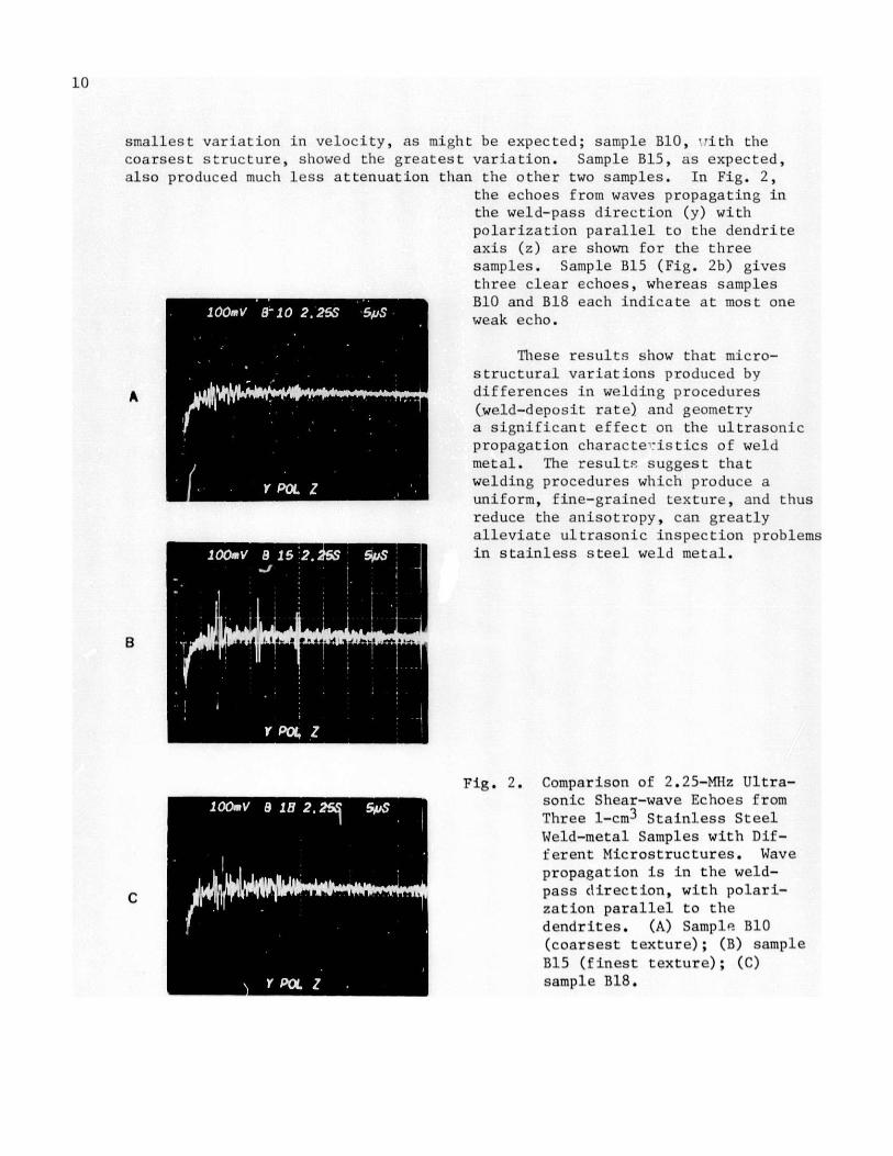
smallest variation in velocity, as might be expected; sample B10, -ith the
coarsest structure, showed the greatest variation. Sample B15, as expected,also produced much less attenuation than the other two samples. In Fig. 2,
the echoes from waves propagating in
the weld-pass direction (y) with
polarization parallel to the dendrite
axis (z) are shown for the threesamples. Sample B15 (Fig. 2b) givesthree clear echoes, whereas samplesB10 and B18 each indicate at most oneweak echo.
These results show that micro-structural variations produced by
A differences in welding procedures
(weld-deposit rate) and geometrya significant effect on the ultrasonicpropagation characte-istics of weld
metal. The results suggest that
welding procedures which produce auniform, fine-grained texture, and thus
reduce the anisotropy, can greatly
alleviate ultrasonic inspection problems1m in stainless steel weld metal.
Fig. 2. Comparison of 2.25-Mhz Ultra-
sonic Shear-wave Echoes from
Three 1-cm3 Stainless Steel
Weld-metal Samples with Dif-
ferent Microstructures. Wave
propagation is in the weld-
C pass direction, with polari-zation parallel to the
dendrites. (A) Sample B10
(coarsest texture); (B) sample
B15 (finest texture); (C)
sample B18.
11
III. EFFECTS OF AGING ON ULTRASONIC VELOCITY AND ATTENUATION
A. 308CRE Welds
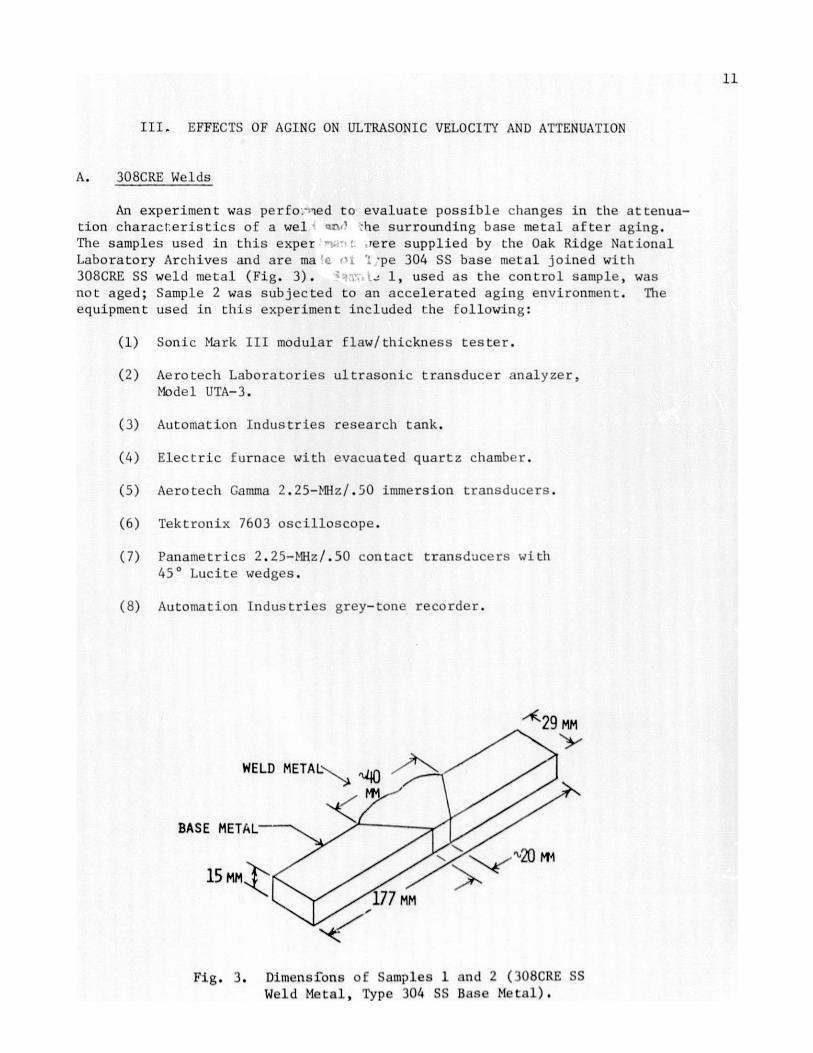
An experiment was perfo.:-ed to evaluate possible changes in the attenua-
tion characteristics of a wel W -he surrounding base metal after aging.The samples used in this exper :ere supplied by the Oak Ridge NationalLaboratory Archives and are ma ':pe 304 SS base metal joined with
308CRE SS weld metal (Fig. 3). - 1, used as the control sample, was
not aged; Sample 2 was subjected to an accelerated aging environment. The
equipment used in this experiment included the following:
(1) Sonic Mark III modular flaw/thickness tester.
(2) Aerotech Laboratories ultrasonic transducer analyzer,Model UTA-3.
(3) Automation Industries research tank.
(4) Electric furnace with evacuated quartz chamber.
(5) Aerotech Gamma 2.25-MHz/.50 immersion transducers.
(6) Tektronix 7603 oscilloscope.
(7) Panametrics 2.25-MHz/.50 contact transducers with
450 Lucite wedges.
(8) Automation Industries grey-tone recorder.
' 29MM
WELD METAL
BASE METAL-
15 MM ^2
177 MM
Fig. 3. Dimensions of Samples 1 and 2 (iH8CRE SSWeld Metal, Type 304 SS Base Metal).

12
Before Sample 2 was aged, the ultrasonic characteristics of the twosamples were compared using a 2.25-MHz longitudinal beam perpendicular to theside surface of the welds; no differences were detected. After the initialultrasonic inspection, Sample 2 was wrapped in tantalum foil and placed in aquartz tube which was then evacuated, back-filled with argon gas, and sealed.The quartz tube was then placed in an electric furnace and aged for 500 h at
a constant temperature of 593*C. After this treatment, Samples 1 and 2 wereagain ultrasonically inspected. Sample 2 was subsequently returned to the
electric furnace and aged for an additional 500 h. After the second 500-h
going , Samples 1 and 2 were again ultrasonically inspected. Sample 2 was then
returned to the furnace for a final aging of 1000 h (for a total of 2000 h).
Four methods of ultrasonic inspection were employed during this experi-ment: (1) Longitudinal beam, pulse-echo mode, perpendicular to the sidesurface of the weld (Fig. 4); (2) longitudinal beam, pitch-catch mode, 450in the metal (Fig. 5); (3) shear beam, pitch-catch mode, 450 in the metal
(Fig. 6); and (4) 450 shear beam, through-transmission mode (Fig. 7). Methods
(1), (2), and (3) utilized a "C"-scan tank with water as the coupling medium.
With the C-scan method, light areas of the image represent maximum attenuation
(Fig. 8). Method (4) used Sonotrace 30 as the coupling medium, with hand-held
transducers on each side of the weld.
PULSER-RECEIVER
90 9 CM190
.J SAMPLE
Fig. 4. I'raasducer ArrangementsI or Long itud inal Beam,Pu I eo-echo Mode, Per-
pond lvular to Surface.
PULSER 1 RECEIVER12.5CM
13.5 CM
19.50
SAMPLE
450 IN METAL
PULSER RECEIVER
7,5CM CM
, 12 CM
10050'%
I.
~1SAMPLE
450 IN METAL
Fig. 5. Transducer Arrangement forLongitudinal Beam, Pitch-(:atch Mode, 450 in Metal.
Fig. 6. 'I'ransducer Arrangement forShear Beam, Pitch-CatchMode, 450 in Metal.
LUCITE WEDGE
F-SAMP'LE
WELDRZON RECEIVER
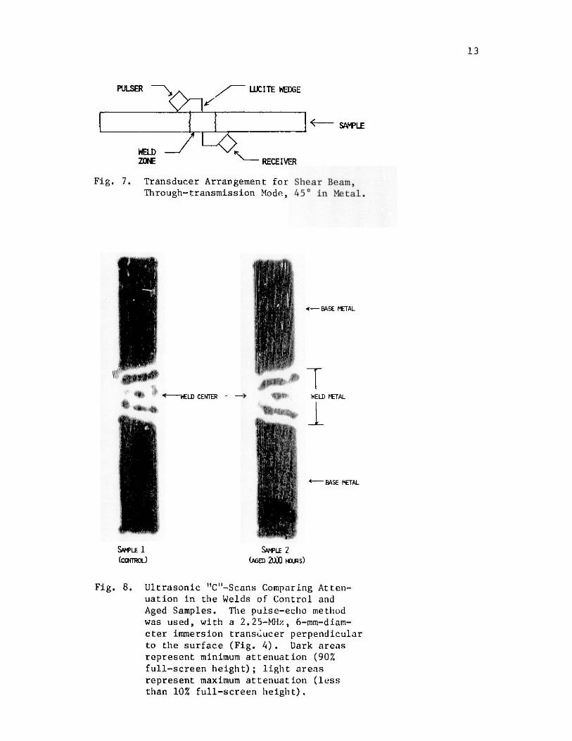
Fig. 7. Transducer Arrangement for Shear Beam,Through-transmission Mode, 450 in Metal.
I
r gl
II 4l
I
v
r11II''
t
AIH -WELD CENTER-li ip~ c .
S*VLE 1(cosmOL)
4- BASE METAL
ELD METAL
t BASE METAL
SNwLE 2(AGED 2L)O HURS)
Fig. 8. Ultrasonic "C"-Scans Comparing Atten-
uation in the Welds of Control and
Aged Samples. The pulse-echo methodwas used, with a 2.25-MHz, 6-mm-diam-eter immersion transducer perpendicularto the surface (Fig. 4). Dark areasrepresent minimum attenuation (90%
full-screen height); light areasrepresent maximum attenuation (less
than 10% full-screen height).
PULSER
13

14
Table II shows the results obtained for each ultrasonic testing method
after Sample 2 had been aged a total of 2000 h. Ratio 1 compares the levelsof ultrasonic-signal transmission through the base metal vs the weld metal.
Ratio 1 also compares the attenuation characteristics of base and weld metal
for each sample. Ratio 2 compares the weld-metal ultrasonic-signal trans-
mission of Sample 1 vs Sample 2. Ratio 3 compares the base-ietal ultrasonic-
signal transmission of Sample 1 vs Sample 2.
As shown in Table II and Fig. 8, aging did not significantly change theattenuation characteristics of the base metal or weld metal, or the attenua-
tion ratio of base metal vs weld met-Al, at a frequency of 2.25 MHz. Although
no effect of aging was seen at 2.25 Miz, higher-frequency waves may be affectedby the presence of carbides and intermotallic phases. However, preliminary
examinations at 10 MHz with normal-incidence and 450 shear pulse-echo wavezshowed no detectable variation in apparent attenuation between aged and unagedsamples. Thus, at frequencies used for ultrasonic NDE (< 10 MHz), no effectof aging in 308CRE weld metal is seen.
B. TyPe 316 Stainless Steel
1. Samples
The tests described below were performed to investigate the possi-
bility that ultrasonic attenuation and velocity in Type 316 austenitic stain-
less steel might change during long-term aging of the material. Two samples,each 76 x 38 x 16 mm (3 x 1.5 x 0.63 in.) in size, were cut from a single
plate. One sample was retained as the control and the other was aged at 600'C
in a muffle furnace in air.
TABE It. Ratios of Ultrasonic Signals in theControl and Aged Weld Samples
Ratios of Ultrasonic-signal Amplitudes
base wel.db baseb
Pit rison etweld weld base
hispkc tion method Instrument Samplea (Ratio 1) (Ratio 2) (Ratio 3)
Longitudinal, Sonic Mk 11 1 1.4:1 1:1 1:1pu ise--echo 1.4:1
l.ongitudinal 45', Sonic Mk 111 1 2.9:1 1:1 1:1pit ch- -It ch 2 2.9:1
Shear 450 1ITA-3 1 11.2:1 1:1 1:1p1tch--ct m ch 2 11.2:1
She r 450, Sonic Mk l11 1 - 1:1 1:1through-transmission
"Sample 1 - control.Sample 2 - aged 2000 I.
Sample 2

15
2. Attenuation
In this experiment, the attenuation was determined by a MATEC modularpulser-receiver system (Fig. 9). The system consists of a Model 6000 main-frame, a Model 950 pulser-receiver module (which allows discrete tuning from1 to 20 MHz), a Mode]. 1204-A exponential generator, and a Tektronix 564B os-cilloscope to display the received signals and the exponential ttenuationcomparator pattern. The system operated in the pulse-echo mode and the rec-tified rf echoes from the initial pulse were displayed along the time axis ofthe oscilloscope. Ideally, the amplitudes of successive echoes decrease ex-ponentially, so that their decay may be matched by the exponential decay gen-erated by the Model 1204-A. The settings on the Model 1204-A necessary toproduce the desired decay curve defined the attenuation a in the material inunits of dB/ps.
The attenuation a was measured as a function of frequency. Trans-
ducers (Automation Industcies, Panametrics, and Aerotech) 6 to 19 mm in diam-
eter, with fundamental frequencies ranging from 2 to 10 MHz, were used. Thetransducers were operated in both the longitudinal and shear modes and were
driven at their fundamental frequency, and where possible, at odd harmonics.
Glycerol was the bonding agent.
Attenuation data obtained on the control sample and on the sample
aged at 60U0 C for 500 and 2500 h are presented in Table III. At a givenfrequency, a could vary by a factor of 2 to 5, depending on transducer geometry
and whether a fundamental or a harmonic frequency was employed. In general,OL does increase with frequency (Table III), bur again, the magnitude of theincrease depends upon whether fundamental o harmonic frequencies are employed.More importantly, it is evident that the setter in the two sets of a measure-ments on the control (unaged) sample is at least as large as the variationsbetween the control and aged samples. Thus, longitudinal attenuation forfrequencies between 2.25 and 15 Mhz is apparently aot sensitive to structuralchanges in Type 316 SS aged at 600*C for up to 2500 i.
MODEL 6000 - MODEL EXPONENTI4IL CURVE1204 A
MODEL RECTIFIED ECHOES950
rf OSCILLOSCOPEPULSE
TRANSDUCER
SAMPLE
Fig. 9. NAITh: System for Mvasuri ng Attvnitilon
of il trasonic Waves.

16
TABLE III. Apparent Attenuation in Type 316 SS
Nominal a, dB/psFrequency, Aged Aged
M11z Controla 500 h Controla 2500 h
2.25 0.69 0.62 0.77 0.75
6.75 0.96 0.96 0.66 0.39
11.25 2.34 2.34 1.95 2.63
15.00 1.0 1.0 1.34 1.38
aSame sample.
On the basis of these data, future emphasis will be placed on meas-
urement of a by two Aerotech transducers: 2.25-MHz, 0.25-in. (SN 016243)
and 15-M1z, 0.25-in. (SN A30611). The 2.25-MHz transducer would provide dataat the fundamental and intermediate harmonics. The 15-MiPz transducer would
provide data at the fundamental, for which low-frequency diffraction losseswould be minimized.
It might be well to mention that in the present system, the trans-mit ted or received frequencies are not actually measured. Frequency is
LUJ'PVWd by one of two means:
(a) IL can be assumed that the transducer operates exactlyat the nominal, fundamental, and odd harmonics;
(b) It can be assumed that the dial settings (which arecalibrated for an rf signal into an unloaded transducer)define the actual frequency of the loaded transducer.
3. Velocity of Sound
The velocity of sound in the aged and control samples of Type 316 SSwas measured using the echo-overlap technique. An Aerotech UTA-3 pulser-receiver was used with a Tektronix Model 7904 oscilloscope with 7B80 and 7185time bases. Panametric 13-mm normal-incidence shear-wave probes operating at
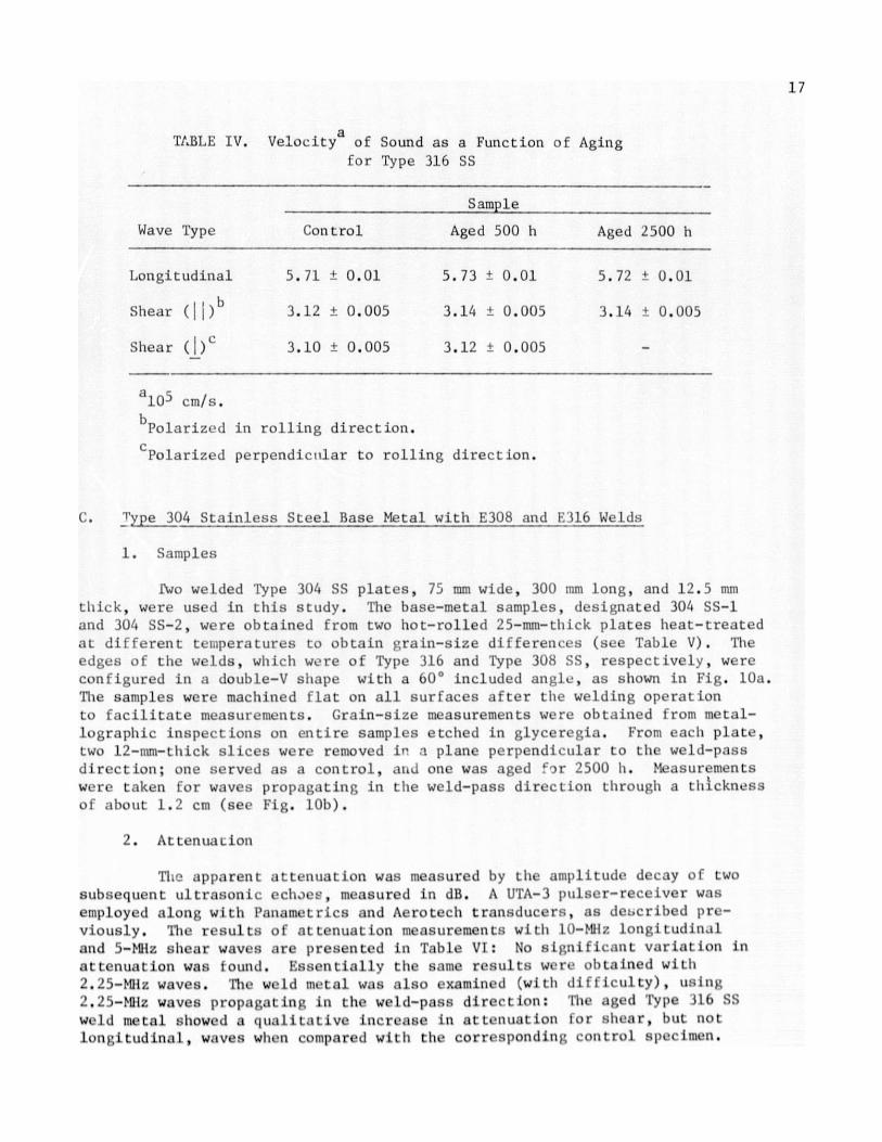
M1iz and Aerotech 6-mm normal-incidence longitudinal-wave probes operatingat 10 MHz were employed. A Tektroni- Model 184 time-mark generator was usedto calibrate the time base. The velocity of sound for the shear waves wasmeasured for wave polarizations parallel (I|) and perpendicular ( ) to therolling direction of the sample. Results are shown in Table IV. A very slightincrease in velocity of sound is observed in these samples after aging: Forlongitudinal waves Av/v = 0.3% 0.3%, and for shear waves Av/v = 0.6% 0.3%.Thiis small increase should not affect the reliability of flaw detection inType 316 SS.
17
TABLE IV. Velocity of Sound as a Function of Agingfor Type 316 SS
Sample
Wave Type Control Aged 500 h Aged 2500 h
Longitudinal 5.71 0.01 5.73 0.01 5.72 0.01
Shear (1 |)b 3.12 0.005 3.14 0.005 3.14 0.005
Shear (1), 3.10 0.005 3.12 0.005 -
a1 0 5 cm/s.
bPolarized in rolling direction.
cPolarized perpendicular to rolling direction.
C. Type 304 Stainless Steel Base Metal with E308 and E316 Welds
1. Samples
fwo welded Type 304 SS plates, 75 mm wide, 300 mm long, and 12.5 mmthick, were used in this study. The base-metal samples, designated 304 SS-1
and 304 SS-2, were obtained from two hot-rolled 25-mm-thick plates heat-treatedat different tLmperatures to obtain grain-size differences (see Table V). Theedges of the welds, which were of Type 316 and Type 308 SS, respectively, wereconfigured in a double-V shape with a 60* included angle, as shown in Fig. 10a.The samples were machined flat on all surfaces after the welding operationto facilitate measurements. Grain-size measurements were obtained from metal-lographic inspections on entire samples etched in glyceregia. From each plate,two 12-mm-thick slices were removed in a plane perpendicular to the weld-passdirection; one served as a control, and one was aged for 2500 hi. Measurementswere taken for waves propagating in the weld-pass direction through a thicknessof about 1.2 cm (see Fig. 10b).
2. Attenuation
TlI. apparent attenuation was measured by the amplitude decay of twosubsequent ultrasonic echaes, measured in dB. A UTA-3 pulser-receiver wasemployed along with Panametrics and Aerotech transducers, as described pre-viously. Tie results of attenuation measurements with 10-Mhz longitudinaland 5-Miz shear waves are presented in Table VI: No significant variation inattenuate ion was s ound. Essentially the same results were obtained with2.25-MIz waves. The we d metal was also examined (with dif Hiculty), using
2.2 )-MIz waves propagmt ing in the weld-pass direct ion: The aged Type 116 SSweld metal showed a qual itative increase in attenuzat ion for shear, but notlongitudinal, waves when compared with the corresponding control Spe imen.

18
TABLE V. Characteristics of Welded Stainless Steel PlatesUsed in Aging Study
Plate Base Heat Base-metal Weld
No. Metal Treatment Grain Size Metal Comments
lA 304 SS-1 1/2 h at ASTM 9, 316 SS Ferrite-free,954*C 15 pm minimum amount of
weld-metal cracking
4A 304 SS-2 1/2 h at ASTM 4, 308 SS o 10% 6-ferrite1121*C 80 pm
304 SS BASE METAL
/j
(a)
316 SS WELD METAL
TRANSDUCERS
(b)
Fig. 10. (a) Sample Configuration of Type 304 SSBars Joined with [316 or E308 Weld Metal.(b) Positions of Transducers Used inVelocity and AL tenuat ion Measurements.
I o a

19
TABLE VI. Apparent Attenuation arid Velocity of Sound inType 304 SS Base Metal
a, dB/ps Sound Velocity, 105 cm/s
Base Grain Size, Wave Frequency Aged AgedMetal Pm and Type Control 2500 h Control 2500 h
304 SS-1 15 10-MHz long. 2.3 0.2 2.0 t 0.2 5.76 0.005 5.77 0.005
5-MHz shear 0.9 0.1 0.9 .0.1 3.13 0.005 3.14 * 0.005
304 SS-2 80 10-MHz long. 2.7 0.2 3.2 t 0.2 5.76 0.005 5.77 0.005
5-MHz shear 1.1 t 0.1 1.2 t 0.1 3.12 0.005 3.13 , 0.005
No difference was seen between the aged and control Type 308 weld specimens.Of all the specimens examined in the present study,' the Type 316 SS weld-metal specimen is the only one in which an increase in attenuation upon aging
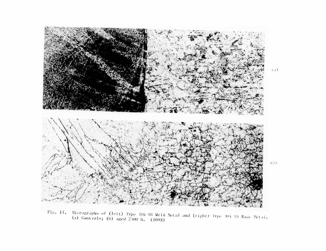
has been observed. The micrographs of the Type 316 SS weld metal (Fig. 11,left) indicate some homogenization and better-defined columnar grain boundaries
after aging, possibly because of carbide precipitation. This change may berelated to the observed attenuation change. No significant microstructuralchange was observed in the Type 308 SS weld metal. Micrographs of Type 316and Type 304 SS base metal after aging for 2500 h showed profuse precipita-tion (probably of carbides) at the grain boundaries, and twinning (see Fig. 12).Some sigma phase may have formed, but no tests were run to confirm this.
3. Velocity of Sound
The velocity of sound in Type 304 SS base metal was measured usingtechniques described previously for Type 316 SS. The data are presented inTable VI.
IV. SUMMARY
Austenitic stainless steel base- and weld-metal samples were aged at600'C for up to 256u h to determine whether the resulting microstructuralchanges in the metal (formation of carbide and intermetallic pha es) wouldhave a deleterious effect on ultrasonic velocity and attenuation and thus on
the reliability of ultrasonic in-service inspections. Type 304 and Type 316 SSbase metals and 308CRE, 308, and 316 weld metals were examined. The ultra-
sonic velocity varied by - 1%; no significant variation in attenuation at
frequencies ti 10 Miz was observed, except for a qualitative increase in atten-uation in the Type 316 SS weld metal. The latter observation may be due to
anomalous changes in microstructure upon aging, as indicated in micrographsof the weld metal. It can be concluded that in general, aging of stainless
steel will not have a de tec t ab l C e f 1 t on the rel iabiii ty of inspect ion
e f fort:; involving the ul trson ic f requeu lces normally used (2-10 Milz).
i . *
-01
~,) (
'4'4
2
~ ... '-'
" - - -a
- _
A -1
%3
'K 44. ;- 4 '. s" .. - -" V .
l'I)
1o
N' rIi VOgrVIphIs of (11) lyp 316 s;; Wi' I Nht *iI . (ri'glIt) l'pc U. SS in. .11(,i) Coll Lrul:; (b ) ,gi l " ()() li ( I()(X)

21
rr
1 '
- - - -
--
r[ )

22
The varying weld-metal texture produced by different welding procedures
was also examined for possible effects on ultrasonic wave propagation. ThreeType 304 SS samples were investigated: The sample with the finest textureshowed the smallest variation in ultrasonic velocity with propagation direc-
tion (3% compared to 28% for the coarsest texture), and the least attenuation
(three echoes in a 1-cm3 specimen versus 1 echo in the coarse-grained speci-mens). It can be concluded that weld procedure, through its influence on
texture, has a dramatic effect on ultrasonic wave propagation characteristics
and therefore on the inspectability of weld metal. Procedures which lead tofine texture are inherently preferable from the point of view of ultrasonic
inspectability.
ACKNOWLEDGMENTS
The authors wish to thank E. Stefanski for editing, E. Hartig andS. Hagamann for typing the report, and W. Sperko, ITT Grinnell, for providingsome samples.
REFERENCES
1. D. S. Kupperman and K. J. Reimann, "Ultrasonic Wave Propagation andAnisotropy in Austenitic Stainless Steel Weld Metal," IEEE Trans. onSonicE and Ultrasonics, Vol. SU-27, No. 1, January 1980, p. 17.
2. B. We.is3 and R. Stickler, "Phase Instabilities During High Temperature
Exposure of 316 Austenitic Stainless Steel," Metallurgical Transacti o;,Vol. 3, April 1972, p. 851.
3. E. 0. Hall and S. 11. Algie, "The Sigma Phase," Metallurgical Reviews,Vol. 11, 1966, p. 61.

23
Distribution for ANL-80-65
Internal:
W. E. MasseyE. S. BeckjordC. E. TillR. AveryL. Burris
D. W. CisselS. A. Davis
B. R. T. FrostE. V. Krivanec
U. E. Simpson
R. J. TeunisR. S. ZenoR. W. WeeksF. A. Nichols
L.J.E.T.M.W.F.J.D.A.A.K.M.R.
T. LloydF. Schumar
M. StefanskiH. BlewittB. BrodskyJ. ShackY. FradinY. Park
Diercks
G. HinsP. L. Turner
L. Merkle
H. MuellerB. Poeppel
(4)
R. W. SiegelD. StahlH. R. ThreshH. Wiedersich
T. F. Kassner
E. FisherD. S. Kupperman (25)M. J. CainesK. J. Reimann (25)N. F. FioreA. B. Krisciunas
ANL Contract FileANL Libraries (2)TIS Files (6)
External:
DOE-TIC, for distribution per UC-79k (189)Manaer, Chicago Operations and Regional Office, DOE
Chief, Office of Patent Counsel, DOE-CORODirector, Technology Management, DOE-CORO
Director, DOE-RRT (2)President, Argonne Universities Association
Materials Science Division Review Committee:
E. A. Aitken, General Electric Co., SunnyvaleG. S. Ansell, Rensselaer Polytechaic Inst.A. Arrott, Simon Fraser U.R. W. Balluffi, Massachusetts Inst. TechnologyS. L. Cooper, U. WisconsinC. Laird, U. PennsylvaniaM. E. Shank, United Technologies Corp.C. T. Tomiizuka, U. Arizona
A. R. C. Westwood, Martin Marietta Labs.