Embed Size (px)
Citation preview

PROCEEDINGS of the 23rd International Congress on Acoustics 9 to 13 September 2019 in Aachen, Germany
Effect of acoustic treatment on fan flutter characteristics
Yu SUN; Xiaoyu WANG; Xiaofeng SUN Beihang University, Fluid and Acoustic Engineering Laboratory, School of Energy and Power Engineering,
Beijing, China
ABSTRACT This paper presents an investigation of the acoustic treatment effect on fan flutter characteristics. A three-dimensional model is proposed to predict the unsteady aerodynamic responses of an oscillating rotor in a finite-length annular duct with the acoustically treated duct walls. In this model, the aerodynamic couplings of oscillating rotor and acoustic liner are analysed in a strict sense by employing the transfer element method, with the unsteady aerodynamic loading distribution on rotor blades predicted by the three-dimensional lifting surface theory and the liner modelled as equivalent monopole sources distributed on hard wall. Moreover, combined with a boundary integral approach, the present model implicitly considers the reflections at duct openings, thus the aerodynamic interactions within such a finite-length duct system can be truly determined. Within the linear scope, the primary perturbations induced directly by blade oscillation and the scattering fields resulted from aerodynamic couplings are superposed to give the total blade loadings, such that the rotor flutter stability can be further evaluated by its unsteady aerodynamic work based on the energy method. A parametric study for the first-order torsion vibration has been conducted, whose results reveal the noticeable impact of the acoustic liner on aeroleastic stability under certain circumstances. Keywords: Fan flutter stability, Acoustic treatment, Transfer element method
1. INTRODUCTION Extensive research efforts have been paid to fan flutter problems since the middle of last century.
However, a brake is on the development of blade flutter control due to the great complexities arising from the fact that any factors affecting the surrounding flow fields or the aeroelastic characteristics of cascade structure are likely to further alter the evolution of this kind of self-excited vibration. Passive suppression techniques of cascade flutter, which were comprehensively assessed by Bendiksen (1) and have revealed little appreciable breakthroughs in the recent decades, usually come with a limited range of utility under the extreme and variable operating conditions of aero engines. By contrast, the concept of suppressing fan flutter with the active control of acoustic treatment on duct wall (2–4) shows a promising prospective. Zhao and Sun (5) have experimentally achieved the active control of duct wall impedance with a kind of perforated liner with adjustable bias flow backed up by a hollow cavity of controllable depth, whose impedance characteristics have been investigated by considerable theoretical and experimental work (6–9). Then we can expect that, once the in-depth knowledge of the aerodynamic impact of acoustically lined wall on fan flutter stability is gained, the corresponding control strategy can be devised for flutter suppression purpose.
Watanabe and Kaji (3) have firstly proven that the change of duct wall impedance could considerably change the aerodynamic damping of oscillating blades. However, the three-dimensional semi-actuator disk model they used has been excessively simplified. By determining the Green’s function for a duct comprised of two parallel infinite flat walls with one of locally reacting impedance, Sun and Kaji (4) further investigated the soft wall effect on the aeroelastic stability of a linear cascade. Their model cannot take into account the annular effect critical for real compressors or turbines as well as the acoustic liners of finite extent. Besides, a troublesome process involved for numerically computing the complex eigenvalues for soft walled duct considerably reduces its efficiency. Hence, more refined and efficient model is still in urgent demand.
In this paper, a three-dimensional semi-analytical model is proposed to predict the unsteady
2041
aerodynamic responses of an oscillating rotor in a finite-length annular duct with the acoustically treated side walls. This model is established based on the transfer element method (10,11), in which each segment of a duct is modelled as a response function in a unified matrix form, called transfer element. Combined with a boundary integral approach (12), this method can derive an overall matrix equation for the entire disturbed field from the continuity conditions imposed on every interface of duct segments as well as on inlet and outlet duct terminations. By solving this matrix equation one can simultaneously determine the disturbed fields both inside and outside the duct, with the existing aerodynamic interactions and the reflections at duct openings thoroughly considered. Moreover, two analytical tools have been used to construct the specific transfer elements for rotor and liner, respectively. First of all, by using Namba’s three-dimensional lifting surface theory (13), the unsteady aerodynamic loadings and the corresponding induced disturbances on blade surfaces in response to the oncoming perturbations can be determined from an upwash integral equation. Secondly, by treating an impedance wall as the corresponding hard wall distributed with the equivalent monopole of fluctuating strength, (14), the scattering effect of finite-length lined section can be effectively modelled. Finally, as indicated by the energy method, the possibility of cascade flutter is evaluated by the total unsteady aerodynamic work exerted on rotor blades, which is obtained by summing up the contributions from both the initial blade oscillation and the aerodynamic couplings of oscillating rotor, acoustic liner and duct openings.
In the following content, a general framework of transfer element will be introduced at first and then its tailored forms for rotor and liner will be discussed subsequently. With the other relevant theoretical tools briefly introduced, the complete process for establishing the present model will be presented. Numerical experiments will be discussed for an improved understanding about how the acoustic treatment on duct wall can influence the rotor flutter stability in a finite-length duct.
2. MODEL AND METHOD DESCRIPTION
2.1 Model Description
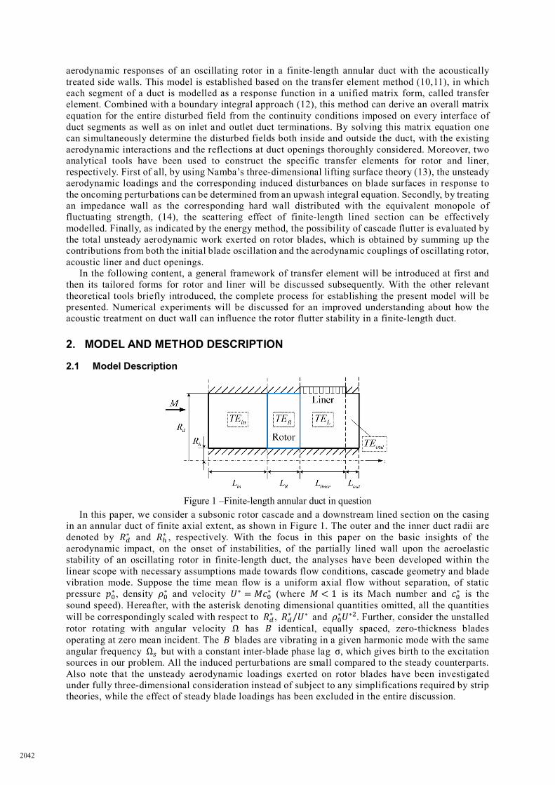
Figure 1 –Finite-length annular duct in question
In this paper, we consider a subsonic rotor cascade and a downstream lined section on the casing in an annular duct of finite axial extent, as shown in Figure 1. The outer and the inner duct radii are denoted by 𝑅𝑅𝑑𝑑∗ and 𝑅𝑅ℎ∗ , respectively. With the focus in this paper on the basic insights of the aerodynamic impact, on the onset of instabilities, of the partially lined wall upon the aeroelastic stability of an oscillating rotor in finite-length duct, the analyses have been developed within the linear scope with necessary assumptions made towards flow conditions, cascade geometry and blade vibration mode. Suppose the time mean flow is a uniform axial flow without separation, of static pressure 𝑝𝑝0∗ , density 𝜌𝜌0∗ and velocity 𝑈𝑈∗ = 𝑀𝑀𝑐𝑐0∗ (where 𝑀𝑀 < 1 is its Mach number and 𝑐𝑐0∗ is the sound speed). Hereafter, with the asterisk denoting dimensional quantities omitted, all the quantities will be correspondingly scaled with respect to 𝑅𝑅𝑑𝑑∗ , 𝑅𝑅𝑑𝑑∗/𝑈𝑈∗ and 𝜌𝜌0∗𝑈𝑈∗2. Further, consider the unstalled rotor rotating with angular velocity Ω has 𝐵𝐵 identical, equally spaced, zero-thickness blades operating at zero mean incident. The 𝐵𝐵 blades are vibrating in a given harmonic mode with the same angular frequency Ω𝑠𝑠 but with a constant inter-blade phase lag σ, which gives birth to the excitation sources in our problem. All the induced perturbations are small compared to the steady counterparts. Also note that the unsteady aerodynamic loadings exerted on rotor blades have been investigated under fully three-dimensional consideration instead of subject to any simplifications required by strip theories, while the effect of steady blade loadings has been excluded in the entire discussion.
2042
2.2 Method of Calculation The difficulties in predicting unsteady rotor response in a partially lined duct of finite axial extent
mainly arise from two respects. Firstly, the disturbances everywhere within a duct are tightly coupled and simultaneously changing, subject to all the scatterings of inner components as well as the reflections at duct open ends. So one cannot truly determine the disturbed fields unless the response function of the entire duct system is constructed as a whole, with all the coupling effects taken into account. Secondly, the capability of treating a wall boundary condition of non-uniform impedance is required, in the preference for a time-saving process. To these ends, we suggest a semi-analytical model developed by using the transfer element method combined with a boundary integral equation, in which the three-dimensional lifting surface theory is employed to derive the rotor response function while the acoustically lined section is equivalently modelled as a rigid wall with the monopole sources of fluctuating strength distributed on it. 2.2.1 Transfer Element Method
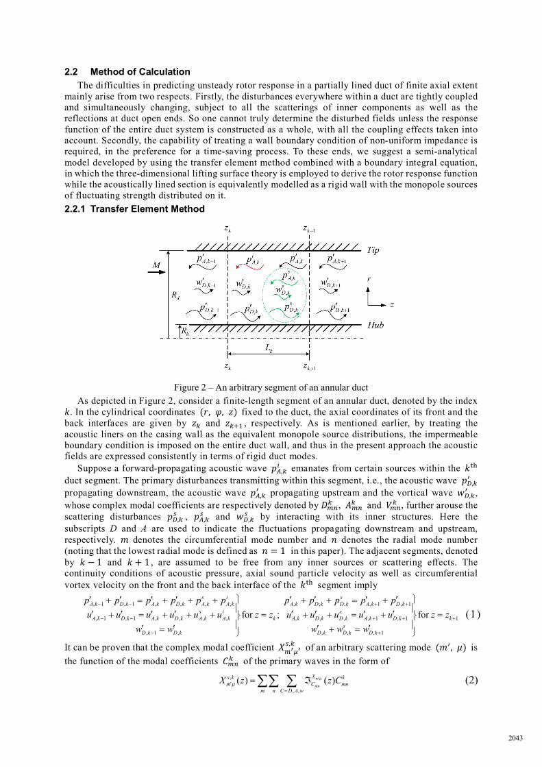
Figure 2 – An arbitrary segment of an annular duct As depicted in Figure 2, consider a finite-length segment of an annular duct, denoted by the index
𝑘𝑘. In the cylindrical coordinates (𝑟𝑟, 𝜑𝜑, 𝑧𝑧) fixed to the duct, the axial coordinates of its front and the back interfaces are given by 𝑧𝑧𝑘𝑘 and 𝑧𝑧𝑘𝑘+1 , respectively. As is mentioned earlier, by treating the acoustic liners on the casing wall as the equivalent monopole source distributions, the impermeable boundary condition is imposed on the entire duct wall, and thus in the present approach the acoustic fields are expressed consistently in terms of rigid duct modes.
Suppose a forward-propagating acoustic wave 𝑝𝑝𝐴𝐴,𝑘𝑘𝑖𝑖 emanates from certain sources within the 𝑘𝑘th
duct segment. The primary disturbances transmitting within this segment, i.e., the acoustic wave 𝑝𝑝𝐷𝐷,𝑘𝑘′
propagating downstream, the acoustic wave 𝑝𝑝𝐴𝐴,𝑘𝑘′ propagating upstream and the vortical wave 𝑤𝑤𝐷𝐷,𝑘𝑘
′ , whose complex modal coefficients are respectively denoted by 𝐷𝐷𝑚𝑚𝑚𝑚
𝑘𝑘 , 𝐴𝐴𝑚𝑚𝑚𝑚𝑘𝑘 and 𝑉𝑉𝑚𝑚𝑚𝑚
𝑘𝑘 , further arouse the scattering disturbances 𝑝𝑝𝐷𝐷,𝑘𝑘
𝑠𝑠 , 𝑝𝑝𝐴𝐴,𝑘𝑘𝑠𝑠 and 𝑤𝑤𝐷𝐷,𝑘𝑘
𝑠𝑠 by interacting with its inner structures. Here the subscripts D and A are used to indicate the fluctuations propagating downstream and upstream, respectively. 𝑚𝑚 denotes the circumferential mode number and 𝑛𝑛 denotes the radial mode number (noting that the lowest radial mode is defined as 𝑛𝑛 = 1 in this paper). The adjacent segments, denoted by 𝑘𝑘 − 1 and 𝑘𝑘 + 1 , are assumed to be free from any inner sources or scattering effects. The continuity conditions of acoustic pressure, axial sound particle velocity as well as circumferential vortex velocity on the front and the back interface of the 𝑘𝑘th segment imply
, 1 , 1 , , , , , , , , 1 , 1
, 1 , 1 , , , , , , , , 1 , 1
, 1 , , , , 1
for ; for
s i sA k D k A k D k A k A k A k D k D k A k D k
s i sA k D k A k D k A k A k k A k D k D k A k D k
sD k D k D k D k D k
p p p p p p p p p p pu u u u u u z z u u u u u
w w w w w
− − + +
− − + +
− +
′ ′ ′ ′ ′ ′ ′ ′ + = + + + + + = + ′ ′ ′ ′ ′ ′ ′ ′+ = + + + = + + = + ′ ′ ′ ′= + =
1 kz z += (1)
It can be proven that the complex modal coefficient 𝑋𝑋𝑚𝑚′𝜇𝜇′𝑠𝑠,𝑘𝑘 of an arbitrary scattering mode (𝑚𝑚′, 𝜇𝜇) is
the function of the modal coefficients 𝐶𝐶𝑚𝑚𝑚𝑚𝑘𝑘 of the primary waves in the form of
,
, ,( ) ( )m
mn
Xs k km C mn
m n C D A wX z z Cµ
µ′
′=
= ℑ∑∑ ∑ (2)
2043
where ℑ𝐶𝐶𝑚𝑚𝑚𝑚
𝑋𝑋𝑚𝑚′𝜇𝜇′ is referred to as the “scattering multiplier”. It is well-known that the orthogonality of the eigenfunctions of a hard-walled duct can transform Eqs. (1) into a series of mode-matching equations. Then, we can further define the multiplier of the unknown primary mode coefficient 𝐶𝐶𝑚𝑚𝑚𝑚
𝑘𝑘 in the resulting mode-matching equations as the “transfer multiplier ℘𝐶𝐶𝑚𝑚𝑚𝑚
𝑘𝑘 ”. All the interface matching conditions lead to an overall matrix equation
[ ] [ ]mn℘ ⋅ =C I (3) The submatrix [℘𝑘𝑘] of its coefficient matrix, composed of all the transfer multipliers of the unknown modal coefficients 𝐶𝐶𝑚𝑚𝑚𝑚
𝑘𝑘 (𝐶𝐶 = 𝐴𝐴,𝐷𝐷 and 𝑉𝑉), is defined as a transfer element. Then we know that once the scattering multiplier ℑ embodied the inner scatterings of a segment is determined, the corresponding transfer element can be obtained subsequently.
Intuitively, since disturbances propagate in a hollow rigid duct without any scatterings, the scattering multipliers will vanish when it comes to an empty duct segment with hard side walls, thus leading to the simplest form of the corresponding transfer element. The application of the transfer element method to a finite-length segment lined with locally reacting liner has been derived in detail in (12), where Eqs. (22-25) can yield the corresponding scattering multipliers.
Table 1 – Mode and frequency characteristics
At the oscillating rotor Circumferential mode numbers Frequencies
Primary waves 𝑚𝑚 = 𝑠𝑠𝐵𝐵 + 𝑉𝑉𝜎𝜎 𝜔𝜔 = Ω𝑠𝑠 +𝑚𝑚Ω
Scattering waves 𝑚𝑚′ = 𝑠𝑠′𝐵𝐵 + 𝑚𝑚 = (𝑠𝑠 + 𝑠𝑠′)𝐵𝐵 + 𝑉𝑉𝜎𝜎 𝜔𝜔′ = 𝑠𝑠′𝐵𝐵Ω+ 𝜔𝜔 = Ω𝑠𝑠 + 𝑚𝑚′Ω Note: the inter-blade phase parameter 𝑉𝑉𝜎𝜎 = 𝜎𝜎𝐵𝐵/2𝜋𝜋.
Based on the three-dimensional lifting surface theory, the scattering multipliers in the transfer element for a rotor of 𝐵𝐵 identical, equally spaced blades in an annular hard-walled duct can be written as follow:
0
( ) ( , , ) ( , , , , , , )dm mn
mnh
R CaX CC X aR
z p r z K r r z z B C m dz drµ ω ω µ′ ′ ′ ′ ′ ′ ′ ′ ′ℑ = ∆ ⋅ − ⋅∫ ∫ (4)
where 𝐶𝐶/𝑋𝑋 = 𝐷𝐷,𝐴𝐴 and 𝑉𝑉 and 𝐶𝐶𝑎𝑎 denotes the axial length of blade chord, which is assumed to be constant along the blade span. The coordinates of source point and observation point in the cylindrical frame of reference fixed to the duct are respectively given by (𝑟𝑟′, 𝜑𝜑′, 𝑧𝑧′) and (𝑟𝑟, 𝜑𝜑, 𝑧𝑧). 𝑝𝑝𝐶𝐶𝑚𝑚𝑚𝑚 is the unsteady blade loading on rotor blade surface resulted from the primary mode (𝑚𝑚,𝑛𝑛) of the upwash disturbance (𝑝𝑝𝐷𝐷,𝑘𝑘
′ , 𝑝𝑝𝐴𝐴,𝑘𝑘′ or 𝑤𝑤𝐷𝐷,𝑘𝑘
′ ) with the incident frequency ω and the modal coefficient equal to unit. Moreover, the kernel function 𝐾𝐾𝑋𝑋 indeed denotes the mode coefficient 𝑋𝑋𝑚𝑚′𝜇𝜇′ of the scattering disturbances induced by a row of pressure dipoles of unit fluctuating amplitude.
It is known that the circumferential mode numbers and the angular frequencies of the scattering waves generated at such a rotor are related to those of the primary disturbances by
m s B ms Bω ω
′ ′= +′ ′= + Ω
(5)
Therefore, it can be proven that both the primary disturbances and the scattering disturbances generated at the oscillating rotor in question are comprised of an infinity number of the modal components in the uniform mode and frequency characteristics shown in Table 1.
So far, all the scattering multipliers for the duct segments involved in the present model have been briefly discussed, and the relevant transfer elements can be built up correspondingly. 2.2.2 Boundary Integral Equation
In order to match the disturbed fields inside of the duct with the radiation fields outside of it, the matching conditions on the duct openings based on the classic Helmholtz integral (14)
0
0( , ) ( )( ) ( ) ( ) ( , ) ( )S
G P Q QC P p P Q G P Q dS Qn n
∂ ∂Ψ= Ψ − ⋅ ∂ ∂ ∫ (6)
where the velocity potential Ψ = 𝑝𝑝′𝑒𝑒−𝑖𝑖𝑘𝑘0𝑀𝑀𝑀𝑀/(1−𝑀𝑀2) (𝑘𝑘0 = 𝜔𝜔 𝑐𝑐0⁄ ) and 𝐺𝐺0 is the free-space Green’s function, is applied in combination with the transfer element matrix in Eq. (3) to construct an overall response function of the duct system in a matrix form (10).
2044
2.2.3 Upwash Velocity Assuming all the blades are vibrating harmonically with the same angular frequency Ω𝑠𝑠, the blade
displacement function ξ(𝑟𝑟′, 𝑧𝑧′) in this paper is chosen to be exactly the same with Eq. (24) in Ref.(15):
( ) ( )2 2( , ) ( ) / 1 / ( ) ( ) 1 /a er z H C h r r U r z z r Uα βξ θ= ⋅ ⋅ + Ω + Θ ⋅ ⋅ − ⋅ + Ω (7)
The first term on the right-hand side of Eq. (7) represents the blade displacement due to the bending vibration of order 𝛼𝛼 while the second term is contributed by the torsion vibration of order 𝛽𝛽. The normalized radial distribution functions of the bending vibration and the torsion vibration are ℎ𝛼𝛼(𝑟𝑟) and 𝜃𝜃𝛽𝛽(𝑟𝑟), and the complex vibration amplitudes are 𝐻𝐻 and Θ, respectively. In this paper, the torsional axis 𝑧𝑧 = 𝑧𝑧𝑒𝑒 is assumed to be located on the mid-chord position. Taking the blade oscillation in the given manner ξ(𝑟𝑟, z)𝑒𝑒𝑖𝑖Ω𝑠𝑠𝑡𝑡+(𝑗𝑗−1)𝜎𝜎 (𝑗𝑗 = 1,⋯ ,𝐵𝐵) as the excitation source, the upwash velocity of the disturbances acting on rotor blade surfaces can then be determined by
( 1)ˆ D ( , ) / Dsi jr z e τ σϕ ξ τΩ + − ′ ′ = ⋅ u (8)
2.2.4 Unsteady aerodynamic work With Namba’s definition (15) of the complex work coefficient
2 2 2
01 / ( , ) ( , )d a
h
R C
w RC r U p r z r z dzdrπ ξ= + Ω ⋅ ⋅∫ ∫
(9)
introduced to the present model, the likelihood of cascade flutter can be predicted by its imaginary part Im[𝐶𝐶𝑤𝑤] (here the overline represent complex conjugate while Re[ ∙ ] and Im[ ∙ ] in this paper denote the real and the imaginary parts of a complex value, respectively). Indeed, Im[𝐶𝐶𝑤𝑤] is the unsteady aerodynamic work exerted on rotor blade during one period of blade oscillation, thus referred to as the unsteady aerodynamic work coefficient. According to the energy method, the cascade can maintain stable if Im[𝐶𝐶𝑤𝑤] < 0; otherwise, a flutter is expected.
3. RESULTS AND DISCUSSION
3.1 Case Configuration For illustrative purpose, a subsonic rotor subject to the first-order torsion vibration (i.e., β = 1
and 𝐻𝐻 = 0 in Eq. (7)) is considered in this paper. The case configurations are given as follow: 𝑅𝑅ℎ =0.2 and 𝑅𝑅𝑑𝑑 = 1 ; 𝑀𝑀 = 0.35 ; Ω = 2.4744 , 𝐵𝐵 = 30 , 𝐶𝐶𝑎𝑎 = 0.2 and Ω𝑠𝑠𝐶𝐶𝑎𝑎 = 0.5 ; the complex amplitude of the torsion vibration Θ = 𝑒𝑒𝑖𝑖Φ where Φ = −10° . Four transfer elements should be constructed respectively for the four duct segemnts depicted in Figure 1, i.e., the inlet segment empty with hard walls, the second segment containing the oscillating rotor, the third segment containing a locally reacting liner and the outlet segment empty with the hard walls. Their default axial lengths are 𝐿𝐿𝑖𝑖𝑚𝑚 = 3𝐶𝐶𝑎𝑎 , 𝐿𝐿𝑅𝑅 = 𝐶𝐶𝑎𝑎, 𝐿𝐿𝑙𝑙𝑖𝑖𝑚𝑚𝑒𝑒𝑙𝑙 = 2𝐶𝐶𝑎𝑎 and 𝐿𝐿𝑜𝑜𝑜𝑜𝑡𝑡 = 𝐶𝐶𝑎𝑎 , respectively. Two inter-blade phase parameters are investigated in this work: first, 𝑉𝑉𝜎𝜎 = 1 where only the lowest radial, first circumferential mode (i.e., 𝑚𝑚 = 1,𝑛𝑛 = 1) is cut-on in the hard-walled duct of infinite axial extent, and second, 𝑉𝑉𝜎𝜎 = 2 where all the hard-walled duct modes are cut-off.
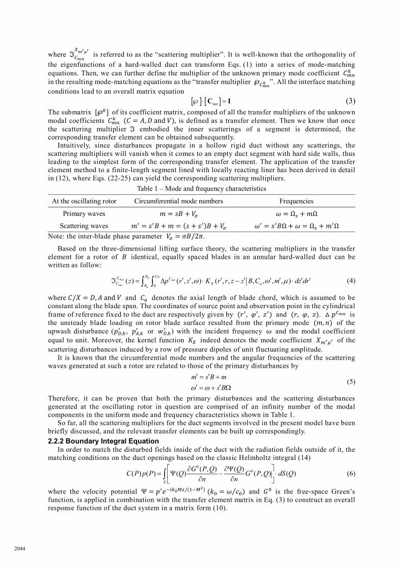
3.2 Numerical Experiments Figure 3 shows the unsteady aerodynamic work coefficient Im[𝐶𝐶𝑤𝑤] plotted against the variation
of the liner reactance Im[𝑍𝑍𝑠𝑠] with its resistance Re[𝑍𝑍𝑠𝑠] held constant as 0.01, 0.10, 0.50, 1.00 and 3.00, respectively. The impedance ranges in these two plots are given to be very broad, out of aeroelastic stability concern rather than any practical acoustic consideration. For the oscillating rotor of concern in the finite-length hard-walled duct, the unsteady aerodynamic work coefficient Im[𝐶𝐶𝑤𝑤] =0.02071 with 𝑉𝑉𝜎𝜎 = 1. With the liner added on the casing, a critical value of the specific reactance around -2.4 is found in Figure 3(a). Within a proper range, where the reactance is smaller than the critical value, the rotor which would flutter in the rigid duct can remain stable with the stabilizing effect of the liner; otherwise, the rotor will flutter and the existence of the liner may even considerably exaggerate the unbalance of the unsteady aerodynamic blade loading distribution due to blade oscillation. For 𝑉𝑉𝜎𝜎 = 2, the rotor is deeply unstable in the finite-length rigid wall, where Im[𝐶𝐶𝑤𝑤] =0.2579. As shown in Figure 3(b), with the liner placed on the prescribed section of a small resistance
2045

and a favourable specific reactance around -3, the rotor is predicted to be effectively stabilized for 𝑉𝑉𝜎𝜎 = 2.
Figure 3 – Variation of Im[𝐶𝐶𝑤𝑤] against the change of the specific impedance 𝑍𝑍𝑠𝑠: (a) 𝑉𝑉𝜎𝜎 = 1; (b) 𝑉𝑉𝜎𝜎 = 2.
Moreover, the unsteady aerodynamic responses of the oscillating rotor is found to be very sensitive to the reactance change when the specific resistance is small. When 𝑍𝑍𝑠𝑠 = 0.01, as the reactance varies from -5 to 5, an oscillating curve of Im[𝐶𝐶𝑤𝑤] is observed both in Figure 3(a) for 𝑉𝑉𝜎𝜎 = 1 and in Figure 3(b) for 𝑉𝑉𝜎𝜎 = 2. With the resistance increasing to 0.10, the drastic oscillation of unsteady aerodynamic work against the increase of the reactance is damped a little, while the reactance values corresponding to those peaks appearing in the curves almost remain unchanged. With the resistance further increased up to 0.50, 1.00 and 3.00, the curves of Im[𝐶𝐶𝑤𝑤] become smooth. Moreover, larger the resistance is, weaker the liner impact upon the rotor responses becomes. Therefore, we guest the phase change of disturbances, which is usually more sensitive to reactance than resistance and turns out to be evident only if less disturbances are absorbed on the liner surface, may take a dominant role in the actual effect of the aerodynamic interactions between oscillating rotor and acoustic liner on flutter stability.
To further investigate the influence of phase shift as well as mode propagation characteristics on this issue, the predictions have also been made by numerically changing the rotor-liner gap as well as the axial length of the liner. For the calculations based on the varying gap, an additional hard-walled hollow segment of the axial length 𝐿𝐿𝑔𝑔𝑎𝑎𝑔𝑔 is introduced between the rotor and the liner, with 𝐿𝐿𝑖𝑖𝑚𝑚 =3𝐶𝐶𝑎𝑎 , 𝐿𝐿𝑅𝑅 = 𝐶𝐶𝑎𝑎 , 𝐿𝐿𝑙𝑙𝑖𝑖𝑚𝑚𝑒𝑒𝑙𝑙 = 2𝐶𝐶𝑎𝑎 and 𝐿𝐿𝑜𝑜𝑜𝑜𝑡𝑡 = 𝐶𝐶𝑎𝑎 kept constant. And when the axial length of the liner 𝐿𝐿𝑙𝑙𝑖𝑖𝑚𝑚𝑒𝑒𝑙𝑙 is changed, we still take 𝐿𝐿𝑖𝑖𝑚𝑚 = 3𝐶𝐶𝑎𝑎 , 𝐿𝐿𝑅𝑅 = 𝐶𝐶𝑎𝑎 and 𝐿𝐿𝑜𝑜𝑜𝑜𝑡𝑡 = 𝐶𝐶𝑎𝑎 . Firstly, for 𝑉𝑉𝜎𝜎 = 1 with the liner of the specific impedance 𝑍𝑍𝑠𝑠 = (0.01,−0.36), the dependencies of Im[𝐶𝐶𝑤𝑤] upon the rotor-liner gap and the liner length are shown in Figure 4, where and the results obtained for the infinitely long duct (denoted by ILD) and those for the finite-length duct (denoted by FLD) are presented in comparison. In a similar fashion, Figure 5 shows the corresponding results for 𝑉𝑉𝜎𝜎 = 2 with 𝑍𝑍𝑠𝑠 = (0.1,−3.0).
For 𝑉𝑉𝜎𝜎 = 1, the mode of 𝑚𝑚 = 1 and 𝑛𝑛 = 1 is cut-on in the duct with entirely rigid walls. By gradually increasing the gap, the phase of the disturbances incident onto the lined section will change sinusoidally, which justifies the periodicity observed in Figure 4(a). Besides, the change of the rotor’s unsteady aerodynamic work against the increase of the liner length also reveals a quasi-sinusoidal pattern, whose periodicity is likely due to the relatively evident effect of the reactance embodied by the phase shift while the small but finite resistance may contribute to its slowly decreasing amplitude.
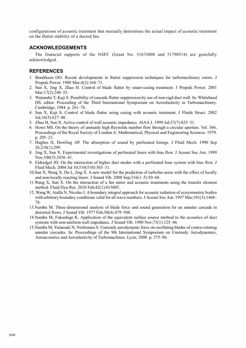
For 𝑉𝑉𝜎𝜎 = 2, where all the modes generated in the hard-walled duct are cut-off, when the gap between the rotor and the liner is not too large, the decaying primary disturbances emitted at the rotor cascade can still arrive at the liner segment and further arouse the scattering waves by interacting with the lined wall. If the scattering fields can significantly alter the primary blade loading distribution, a stabilizing or destabilizing effect will be observed. On the other hand, since all the primary disturbances of cut-off modes will attenuate exponentially on their way to the acoustically lined wall, if the rotor-liner gap is large enough, the liner cannot affect the rotor responses anymore, which is exactly consistent with the results given in Figure 5(a). Besides, remarkable quasi-periodic change of the unsteady aerodynamic work against the increase of 𝐿𝐿𝑙𝑙𝑖𝑖𝑚𝑚𝑒𝑒𝑙𝑙 is observed in Figure 5(b) with 𝑉𝑉𝜎𝜎 = 2 and 𝑍𝑍𝑠𝑠 = (0.1,−3.0). One possible reason behind it can be the modification of mode propagation characteristics in a duct with the side walls of considerable lined area, compared with the duct of the same geometry but with entirely hard walls.
2046
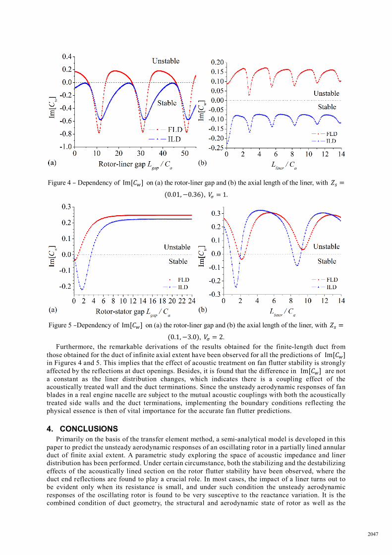
Figure 4 – Dependency of Im[𝐶𝐶𝑤𝑤] on (a) the rotor-liner gap and (b) the axial length of the liner, with 𝑍𝑍𝑠𝑠 =
(0.01,−0.36), 𝑉𝑉𝜎𝜎 = 1.
Figure 5 –Dependency of Im[𝐶𝐶𝑤𝑤] on (a) the rotor-liner gap and (b) the axial length of the liner, with 𝑍𝑍𝑠𝑠 =
(0.1,−3.0), 𝑉𝑉𝜎𝜎 = 2. Furthermore, the remarkable derivations of the results obtained for the finite-length duct from
those obtained for the duct of infinite axial extent have been observed for all the predictions of Im[𝐶𝐶𝑤𝑤] in Figures 4 and 5. This implies that the effect of acoustic treatment on fan flutter stability is strongly affected by the reflections at duct openings. Besides, it is found that the difference in Im[𝐶𝐶𝑤𝑤] are not a constant as the liner distribution changes, which indicates there is a coupling effect of the acoustically treated wall and the duct terminations. Since the unsteady aerodynamic responses of fan blades in a real engine nacelle are subject to the mutual acoustic couplings with both the acoustically treated side walls and the duct terminations, implementing the boundary conditions reflecting the physical essence is then of vital importance for the accurate fan flutter predictions.
4. CONCLUSIONS Primarily on the basis of the transfer element method, a semi-analytical model is developed in this
paper to predict the unsteady aerodynamic responses of an oscillating rotor in a partially lined annular duct of finite axial extent. A parametric study exploring the space of acoustic impedance and liner distribution has been performed. Under certain circumstance, both the stabilizing and the destabilizing effects of the acoustically lined section on the rotor flutter stability have been observed, where the duct end reflections are found to play a crucial role. In most cases, the impact of a liner turns out to be evident only when its resistance is small, and under such condition the unsteady aerodynamic responses of the oscillating rotor is found to be very susceptive to the reactance variation. It is the combined condition of duct geometry, the structural and aerodynamic state of rotor as well as the
2047
configurations of acoustic treatment that mutually determines the actual impact of acoustic treatment on the flutter stability of a ducted fan.
ACKNOWLEDGEMENTS The financial supports of the NSFC (Grant No. 51676008 and 51790514) are gratefully
acknowledged.
REFERENCES 1. Bendiksen OO. Recent developments in flutter suppression techniques for turbomachinery rotors. J
Propuls Power. 1988 Mar;4(2):164–71. 2. Sun X, Jing X, Zhao H. Control of blade flutter by smart-casing treatment. J Propuls Power. 2001
Mar;17(2):248–55. 3. Watanabe T, Kaji S. Possibility of cascade flutter suppression by use of non-rigd duct wall. In: Whitehead
DS, editor. Proceeding of the Third International Symposium on Aeroelasticity in Turbomachinery. Cambridge; 1984. p. 261–76.
4. Sun X, Kaji S. Control of blade flutter using casing with acoustic treatment. J Fluids Struct. 2002 Jul;16(5):627–48.
5. Zhao H, Sun X. Active control of wall acoustic impedance. AIAA J. 1999 Jul;37(7):825–31. 6. Howe MS. On the theory of unsteady high Reynolds number flow through a circular aperture. Vol. 366,
Proceedings of the Royal Society of London A: Mathematical, Physical and Engineering Sciences. 1979. p. 205–23.
7. Hughes IJ, Dowling AP. The absorption of sound by perforated linings. J Fluid Mech. 1990 Sep 26;218(1):299.
8. Jing X, Sun X. Experimental investigations of perforated liners with bias flow. J Acoust Soc Am. 1999 Nov;106(5):2436–41.
9. Eldredgel JD. On the interaction of higher duct modes with a perforated liner system with bias flow. J Fluid Mech. 2004 Jul 10;510(510):303–31.
10.Sun X, Wang X, Du L, Jing X. A new model for the prediction of turbofan noise with the effect of locally and non-locally reacting liners. J Sound Vib. 2008 Sep;316(1–5):50–68.
11.Wang X, Sun X. On the interaction of a fan stator and acoustic treatments using the transfer element method. Fluid Dyn Res. 2010 Feb;42(1):015005.
12. Wang W, Atalla N, Nicolas J. A boundary integral approach for acoustic radiation of axisymmetric bodies with arbitrary boundary conditions valid for all wave numbers. J Acoust Soc Am. 1997 Mar;101(3):1468–78.
13.Namba M. Three-dimensional analysis of blade force and sound generation for an annular cascade in distorted flows. J Sound Vib. 1977 Feb;50(4):479–508.
14.Namba M, Fukushige K. Application of the equivalent surface source method to the acoustics of duct systems with non-uniform wall impedance. J Sound Vib. 1980 Nov;73(1):125–46.
15.Namba M, Yamasaki N, Nishimura S. Unsteady aerodynamic force on oscillating blades of contra-rotating annular cascades. In: Proceedings of the 9th International Symposium on Unsteady Aerodynamics, Aeroacoustics and Aeroelasticity of Turbomachines. Lyon; 2000. p. 375–86.
2048


![The effect of room acoustics on audio event classificationpub.dega-akustik.de/ICA2019/data/articles/001528.pdf · 2019-09-20 · [The effect of room acoustics on audio event classication]](https://img.pdfslide.us/doc/110x75/5e7914886230d15e11145d21/the-effect-of-room-acoustics-on-audio-event-2019-09-20-the-effect-of-room-acoustics.jpg)


![Underwater Sound Localization using Internally Coupled ...pub.dega-akustik.de/ICA2019/data/articles/000795.pdf · function as a Helmholtz resonator []. Both the tympanic plates (instead](https://img.pdfslide.us/doc/110x75/610fb2ed91a7e559ac3b65e2/underwater-sound-localization-using-internally-coupled-pubdega-function-as.jpg)