Embed Size (px)
Citation preview
IEEE TRANSACTIONS ON INDUSTRIAL ELECTRONICS, VOL. 58, NO. 1, JANUARY 2011 21
Efficiency Impact of Silicon Carbide PowerElectronics for Modern Wind Turbine
Full Scale Frequency ConverterHui Zhang, Member, IEEE, and Leon M. Tolbert, Senior Member, IEEE
Abstract—Power electronics is an enabling technology found inmost renewable energy generation systems. Because of its superiorvoltage blocking capabilities and fast switching speeds, siliconcarbide (SiC) power electronics are considered for use in powerconversion units in wind generation systems in this paper. Thepotential efficiency gains from the use of SiC devices in a wind gen-eration system are explored by simulations, with the system mod-eling explained in detail. The performance of the SiC converter isanalyzed and compared to its silicon counterpart at different windspeeds, temperatures, and switching frequencies. The quantitativeresults are based on SiC metal–oxide–semiconductor field-effecttransistor (MOSFET) prototypes from Cree and modern Si in-sulated-gate bipolar transistor (IGBT) products. A conclusion isdrawn that the SiC converters can improve the wind system powerconversion efficiency and can reduce the system’s size and cost dueto the low-loss, high-frequency, and high-temperature propertiesof SiC devices, even for one-for-one replacement for Si devices.
Index Terms—Converter, modeling, metal–oxide–semiconductor field-effect transistor (MOSFET), silicon carbide(SiC), wind generation.
I. INTRODUCTION
VARIABLE speed capability allows a wind turbine tooperate at speeds which produce the greatest amount of
power and minimizes torque perturbations in the drive train[1]–[5]. This capability tends to decrease the overall cost ofenergy because the amount of energy generated is increased andthe cost of the drive train and its maintenance are reduced. Sincethe voltage and frequency of the generated power vary with theturbine speed, a converter is required to reconcile the outputwith the fixed voltage and frequency of the grid [6]–[10].
Several technical and market reports [11]–[13] have recog-nized silicon carbide (SiC) power electronics as a potentialtechnology for wind turbine power converters. The primarybenefits of SiC-based power devices include low losses, hightemperature tolerance, and fast switching. These can be ex-
Manuscript received July 31, 2009; revised December 3, 2009 andFebruary 16, 2010; accepted March 22, 2010. Date of publication April 29,2010; date of current version December 10, 2010.
H. Zhang is with the Department of Electrical Engineering, Tuskegee Uni-versity, Tuskegee, AL 36088 USA (e-mail: [email protected]).
L. M. Tolbert is with the Min Kao Department of Electrical Engineering andComputer Science, The University of Tennessee, Knoxville, TN 37996-2100USA, and also with the Power Electronics and Electric Machinery ResearchCenter, Oak Ridge National Laboratory (ORNL), Knoxville, TN 37932 USA(e-mail: [email protected]).
Color versions of one or more of the figures in this paper are available onlineat http://ieeexplore.ieee.org.
Digital Object Identifier 10.1109/TIE.2010.2048292
ploited to reduce generation losses and increase net energyproduction. The low losses, along with high temperature tol-erance, can also be used to improve the reliability of theconverter and reduce the thermal management requirements.Moreover, fast switching has the potential to reduce the filteringpassive component size and cost, thus, the total cost of thesystem. Reference [13] provides a simulation for the efficiencyperformance of SiC-based converters that might be used in awind turbine and it provides quantitative comparison with com-monly used Si converters. This paper also provides quantitativeresults, but simulations have been updated by using experi-mentally tested characteristics of more recently developed SiCmetal–oxide–semiconductor field-effect transistor (MOSFET)and Schottky diode device prototypes.
II. WIND TURBINE SYSTEM AND MODELING
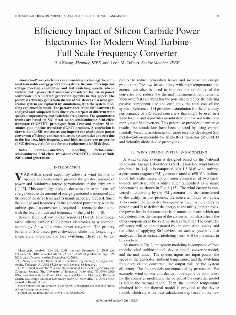
A wind turbine system is designed based on the NationalRenewable Energy Laboratory’s (NREL) baseline wind turbinedescribed in [14]. It is composed of a 1.5 MW wind turbine,a permanent magnet (PM) generator rated at 690 V, a bidirec-tional full scale frequency converter comprised of two back-to-back inverters, and a utility filter (simplified as a singleinductance), as shown in Fig. 1 [15]. The wind energy is con-verted to electricity by the PM generator and then transferredto the utility. In this process, the converter plays two roles:1) to control the generator to capture as much wind energy aspossible and 2) to deliver the energy to the utility. In both roles,the power loss in the converter is of utmost concern, which notonly determines the design of the converter, but also affects theother components in the system, such as the filter. The converterefficiency will be demonstrated by the simulation results, andthe effect of applying SiC devices on such a system is alsoanalyzed. The associated modeling work will be presented inthis section.
As shown in Fig. 2, the system modeling is composed of fourmodels: wind turbine model, device model, converter model,and thermal model. The system inputs are input power, thespeed of the generator, ambient temperature, and the switchingfrequency of the converter. The output will be the systemefficiency. The four models are connected by parameters. Forexample, wind turbine and device models provide parametersfor the converter model, and the output of the converter modelis fed to the thermal model. Then, the junction temperatureobtained from the thermal model is provided to the devicemodel, which starts the next calculation step based on the new
0278-0046/$26.00 © 2011 IEEE
22 IEEE TRANSACTIONS ON INDUSTRIAL ELECTRONICS, VOL. 58, NO. 1, JANUARY 2011
Fig. 1. Wind generation system structure with full scale converter.
Fig. 2. System modeling diagram.
temperature information. Each model is explained in detail inthe following sections.
A. Wind Turbine Model
The wind turbine model is mainly a PM generator model,whose function is to calculate the current, power factor, andthe modulation index, which are needed by the converter modelbased on the input power and the speed of the generator. Theelectrical parameters of the generator studied in this work arelisted in Table I. Assuming that the generator back electro-motive force is in phase with the generator current, then asimplified PM generator model can be developed using a dqrotating coordinate system analysis. With this generator model,the output voltage and current of the generator can be obtained.They are also the ac side current and voltage of the rectifierin the back-to-back converter. Then, based on the relationshipbetween the ac side and the dc voltage in an inverter withsinusoidal pulse width modulation (SPWM) technique, themodulation of the converter can be calculated. The full list ofequations can be found in [13].
B. Device Models
Device models describe the device characteristics related tothe operation losses. In this paper, they are look-up tables orpolynomial functions based on the curve fitting of test results.Most recent SiC MOSFET prototypes were obtained and testedfor both static and dynamic characteristics, which were thenused for curve fitting.
TABLE IWIND GENERATION SYSTEM PARAMETERS
TABLE IIDEVICES USED IN CONVERTERS
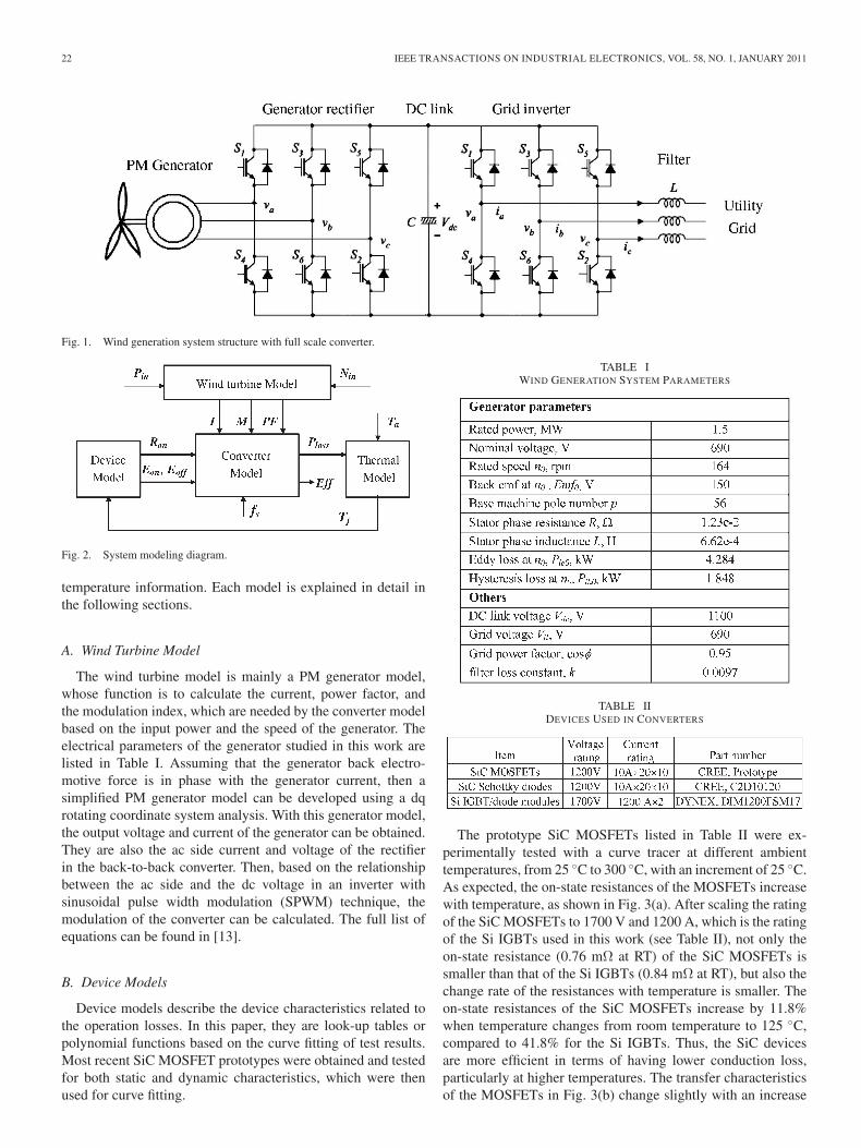
The prototype SiC MOSFETs listed in Table II were ex-perimentally tested with a curve tracer at different ambienttemperatures, from 25 ◦C to 300 ◦C, with an increment of 25 ◦C.As expected, the on-state resistances of the MOSFETs increasewith temperature, as shown in Fig. 3(a). After scaling the ratingof the SiC MOSFETs to 1700 V and 1200 A, which is the ratingof the Si IGBTs used in this work (see Table II), not only theon-state resistance (0.76 mΩ at RT) of the SiC MOSFETs issmaller than that of the Si IGBTs (0.84 mΩ at RT), but also thechange rate of the resistances with temperature is smaller. Theon-state resistances of the SiC MOSFETs increase by 11.8%when temperature changes from room temperature to 125 ◦C,compared to 41.8% for the Si IGBTs. Thus, the SiC devicesare more efficient in terms of having lower conduction loss,particularly at higher temperatures. The transfer characteristicsof the MOSFETs in Fig. 3(b) change slightly with an increase
ZHANG AND TOLBERT: EFFICIENCY IMPACT OF SILICON CARBIDE POWER ELECTRONICS FOR MODERN WIND TURBINE 23
Fig. 3. Static characteristics of the SiC MOSFET at different temperatures.(a) Forward characteristics. (b) Transfer characteristics.
in temperatures above 150 ◦C. This indicates that the changein switching losses of the MOSFETs with temperature will besmall. This is confirmed by the switching tests (Fig. 6).
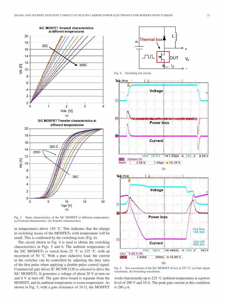
The circuit shown in Fig. 4 is used to obtain the switchingcharacteristics in Figs. 5 and 6. The ambient temperature ofthe SiC MOSFETs is varied from 25 ◦C to 225 ◦C, with anincrement of 50 ◦C. With a pure inductive load, the currentin the switches can be controlled by adjusting the duty ratioof the first pulse when applying a double-pulse control signal.Commercial gate driver IC HCNW3120 is selected to drive theSiC MOSFETs. It generates a voltage of about 20 V at turn-onand 0 V at turn-off. The gate drive board is separate from theMOSFET, and its ambient temperature is room temperature. Asshown in Fig. 5, with a gate resistance of 10 Ω, the MOSFET
Fig. 4. Switching test circuit.
Fig. 5. Test waveforms of the SiC MOSFET (Cree) at 225 ◦C. (a) Gate signalwaveforms. (b) Switching waveforms.
works functionally up to 225 ◦C ambient temperature at a powerlevel of 200 V and 10 A. The peak gate current at this conditionis 280 μA.
24 IEEE TRANSACTIONS ON INDUSTRIAL ELECTRONICS, VOL. 58, NO. 1, JANUARY 2011
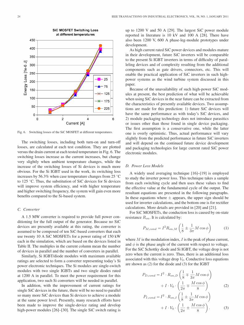
Fig. 6. Switching losses of the SiC MOSFET at different temperatures.
The switching losses, including both turn-on and turn-offlosses, are calculated at each test condition. They are plottedversus the drain current at each tested temperature in Fig. 6. Theswitching losses increase as the current increases, but changevery slightly when ambient temperature changes, while theincrease of the switching losses of Si devices is much moreobvious. For the Si IGBT used in the work, its switching lossincreases by 56.3% when case temperature changes from 25 ◦Cto 125 ◦C. Thus, the substitution of SiC devices for Si deviceswill improve system efficiency, and with higher temperatureand higher switching frequency, the system will gain even morebenefits compared to the Si-based system.
C. Converter
A 1.5 MW converter is required to provide full power con-ditioning for the full output of the generator. Because no SiCdevices are presently available at this rating, the converter isassumed to be composed of ten SiC-based converters that eachuse twenty 10 A SiC MOSFETs for a power rating of 150 kWeach in the simulation, which are based on the devices listed inTable II. The multiples in the current column mean the numberof devices in parallel and the number of converters in parallel.
Similarly, Si IGBT/diode modules with maximum availableratings are selected to form a converter representing today’s Sipower electronic techniques. The Si modules are single-switchmodules with two single IGBTs and two single diodes ratedat 1200 A in parallel. To meet the power requirement for thisapplication, two such Si converters will be needed in parallel.
In addition, with the improvement of current ratings forsingle SiC devices in the future, there will be no need to parallelso many more SiC devices than Si devices to achieve a moduleat the same power level. Presently, many research efforts havebeen made to improve the single-device rating and develophigh-power modules [26]–[30]. The single SiC switch rating is
up to 1200 V and 50 A [29]. The largest SiC power modulereported in literature is 10 kV and 100 A [28]. There havealso been 1200 V, 600 A phase-leg-module prototypes underdevelopment.
As high current rated SiC power devices and modules maturein their development, future SiC inverters will be comparableto the present Si IGBT inverters in terms of difficulty of paral-leling devices and of complexity resulting from the additionalcomponents such as gate drivers, connectors, etc. This willenable the practical application of SiC inverters in such high-power systems as the wind turbine system discussed in thispaper.
Because of the unavailability of such high-power SiC mod-ules at present, the best prediction of what will be achievablewhen using SiC devices in the near future can be extracted fromthe characteristics of presently available devices. Two assump-tions are made for this prediction: 1) future SiC devices willhave the same performance as with today’s SiC devices, and2) module packaging technology does not introduce parasiticsor issues other than those found in single device packaging.The first assumption is a conservative one, while the latterone is overly optimistic. Thus, actual performance will varyslightly from the predicted performance in future SiC invertersand will depend on the continued future device developmentand packaging technologies for large current rated SiC powerelectronic modules.
D. Power Loss Models
A widely used averaging technique [16]–[19] is employedto study the inverter power loss. This technique takes a samplefrom each switching cycle and then uses these values to findthe effective value at the fundamental cycle of the output. Theresultant equations are presented in the following paragraphs.In these equations where ± appears, the upper sign should beused for inverter calculations, and the bottom one is for rectifiercalculations. More details are provided in [20] and [21].
For SiC MOSFETs, the conduction loss is caused by on-stateresistance Ron. It is calculated by:
PM,cond = I2Ron,M
(18± 1
3πM cos φ
)(1)
where M is the modulation index, I is the peak of phase current,and φ is the phase angle of the current with respect to voltage.For the SiC Schottky diode and Si IGBT, the voltage drop is notzero when the current is zero. Thus, there is an additional lossassociated with this voltage drop V0. Conductive loss equationsare shown as (2) for the diode and (3) for the IGBT
PD,cond = I2 · Ron,D
(18∓ 1
3πM cos φ
)
+ I · V0 ·(
12π
∓ M cos φ
8
)(2)
PI,cond = I2 · Ron,I
(18± 1
3πM cos φ
)
+ I · V0 ·(
12π
± M cos φ
8
). (3)
ZHANG AND TOLBERT: EFFICIENCY IMPACT OF SILICON CARBIDE POWER ELECTRONICS FOR MODERN WIND TURBINE 25
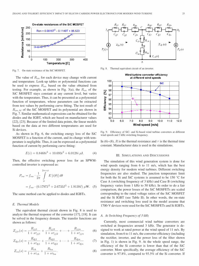
Fig. 7. On-state resistance of the SiC MOSFET.
The value of Ron for each device may change with currentand temperature. Look-up tables or polynomial functions canbe used to express Ron based on the value obtained fromtesting. For example, as shown in Fig. 3(a), the Ron of theSiC MOSFET stays constant at any current level, but varieswith the temperature. Thus, it can be presented as a polynomialfunction of temperature, whose parameters can be extractedfrom test values by performing curve fitting. The test result ofRon,M of the SiC MOSFET and its polynomial are shown inFig. 7. Similar mathematical expressions can be obtained for thediodes and the IGBT, which are based on manufacturer values[22], [23]. Because of the limited data points, the linear modelsbased on the data at two different temperatures are used forSi devices.
As shown in Fig. 6, the switching energy loss of the SiCMOSFET is a function of the current, and its change with tem-perature is negligible. Thus, it can be expressed as a polynomialfunction of current by performing curve fitting:
E(i) = 0.8468i3 + 10.693i2 + 6.0128i μJ. (4)
Then, the effective switching power loss for an SPWM-controlled inverter is expressed as:
Psw = fsw · 12π
2π+φ∫φ
E [i(θ)] dθ
= fsw · (0.1797I3 + 2.6733I2 + 1.9139I) μW. (5)
The same method can be applied to diodes and IGBTs.
E. Thermal Models
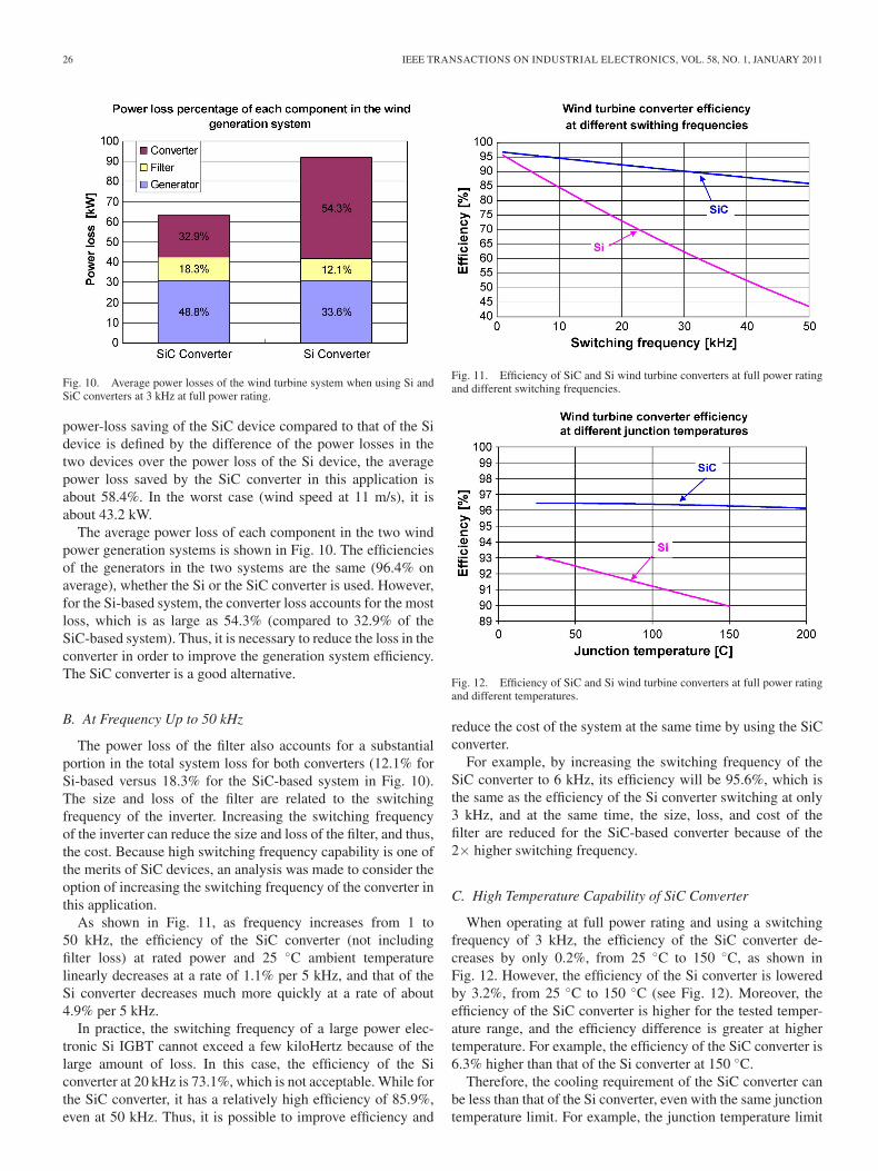
The equivalent thermal circuit shown in Fig. 8 is used toanalyze the thermal response of the converter [17], [18]. It canbe solved in the frequency domain. The transfer functions areshown as follows:
Zjjc(s) =Rjj1
1 + sτjj1+
Rjj2
1 + sτjj2+ · · · + Rjjn
1 + sτjjn(6)
Zdjc(s) =Rdj1
1 + sτdj1+
Rdj2
1 + sτdj2+ · · · + Rdjn
1 + sτdjn(7)
Zca(s) =Rch
1 + sτch+
Rha
1 + sτha. (8)
Fig. 8. Thermal equivalent circuit of an inverter.
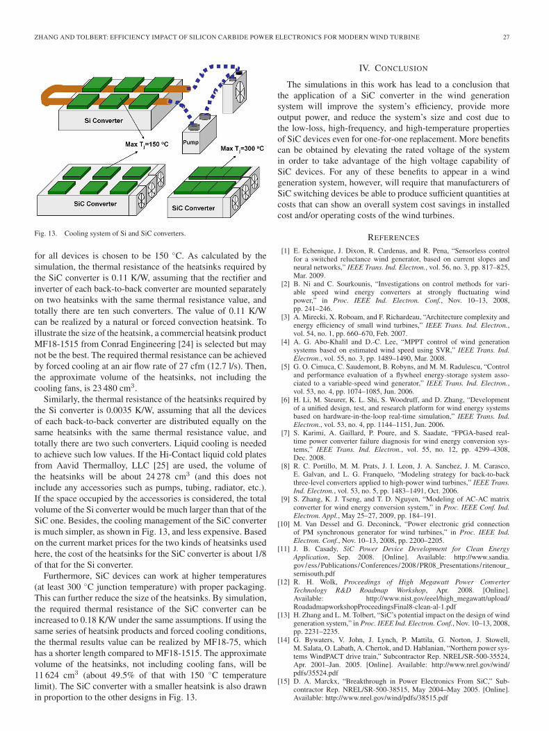
Fig. 9. Efficiency of SiC- and Si-based wind turbine converters at differentwind speeds and 3 kHz switching frequency.
In (6)–(8), R is the thermal resistance and τ is the thermal timeconstant. Manufacturer data is used in the simulations.
III. SIMULATIONS AND DISCUSSIONS
The simulation of this wind generation system is done forwind speeds ranging from 6 to 11 m/s, which has the bestenergy density for modern wind turbines. Different switchingfrequencies are also studied. The junction temperature limitfor both the Si and SiC systems is assumed to be 150 ◦C forCase A (switching frequency of 3 kHz) and Case B (switchingfrequency varies from 1 kHz to 50 kHz). In order to do a faircomparison, the power losses of the SiC MOSFETs are scaledcorresponding to the rated voltage ratios of the SiC MOSFETand the Si IGBT (see Table II). In other words, the on-stateresistance and switching loss used in the model assume that1700-V devices were used for the SiC MOSFETs and Si IGBTs.
A. At Switching Frequency of 3 kHz
Currently, most commercial wind turbine converters areswitched at frequencies around 3 kHz. The generator is de-signed to work at rated power at the wind speed of 11 m/s. Bysimulation, from 6 to 11 m/s, the converter efficiency (includingthe rectifier, inverter, and the power loss of the filter shownin Fig. 1) is shown in Fig. 9. At the whole speed range, theefficiency of the Si converter is lower than that of the SiCconverter. More specifically, the average efficiency of the SiCconverter is 97.8%, compared to 93.5% of the Si converter. If
26 IEEE TRANSACTIONS ON INDUSTRIAL ELECTRONICS, VOL. 58, NO. 1, JANUARY 2011
Fig. 10. Average power losses of the wind turbine system when using Si andSiC converters at 3 kHz at full power rating.
power-loss saving of the SiC device compared to that of the Sidevice is defined by the difference of the power losses in thetwo devices over the power loss of the Si device, the averagepower loss saved by the SiC converter in this application isabout 58.4%. In the worst case (wind speed at 11 m/s), it isabout 43.2 kW.
The average power loss of each component in the two windpower generation systems is shown in Fig. 10. The efficienciesof the generators in the two systems are the same (96.4% onaverage), whether the Si or the SiC converter is used. However,for the Si-based system, the converter loss accounts for the mostloss, which is as large as 54.3% (compared to 32.9% of theSiC-based system). Thus, it is necessary to reduce the loss in theconverter in order to improve the generation system efficiency.The SiC converter is a good alternative.
B. At Frequency Up to 50 kHz
The power loss of the filter also accounts for a substantialportion in the total system loss for both converters (12.1% forSi-based versus 18.3% for the SiC-based system in Fig. 10).The size and loss of the filter are related to the switchingfrequency of the inverter. Increasing the switching frequencyof the inverter can reduce the size and loss of the filter, and thus,the cost. Because high switching frequency capability is one ofthe merits of SiC devices, an analysis was made to consider theoption of increasing the switching frequency of the converter inthis application.
As shown in Fig. 11, as frequency increases from 1 to50 kHz, the efficiency of the SiC converter (not includingfilter loss) at rated power and 25 ◦C ambient temperaturelinearly decreases at a rate of 1.1% per 5 kHz, and that of theSi converter decreases much more quickly at a rate of about4.9% per 5 kHz.
In practice, the switching frequency of a large power elec-tronic Si IGBT cannot exceed a few kiloHertz because of thelarge amount of loss. In this case, the efficiency of the Siconverter at 20 kHz is 73.1%, which is not acceptable. While forthe SiC converter, it has a relatively high efficiency of 85.9%,even at 50 kHz. Thus, it is possible to improve efficiency and
Fig. 11. Efficiency of SiC and Si wind turbine converters at full power ratingand different switching frequencies.
Fig. 12. Efficiency of SiC and Si wind turbine converters at full power ratingand different temperatures.
reduce the cost of the system at the same time by using the SiCconverter.
For example, by increasing the switching frequency of theSiC converter to 6 kHz, its efficiency will be 95.6%, which isthe same as the efficiency of the Si converter switching at only3 kHz, and at the same time, the size, loss, and cost of thefilter are reduced for the SiC-based converter because of the2× higher switching frequency.
C. High Temperature Capability of SiC Converter
When operating at full power rating and using a switchingfrequency of 3 kHz, the efficiency of the SiC converter de-creases by only 0.2%, from 25 ◦C to 150 ◦C, as shown inFig. 12. However, the efficiency of the Si converter is loweredby 3.2%, from 25 ◦C to 150 ◦C (see Fig. 12). Moreover, theefficiency of the SiC converter is higher for the tested temper-ature range, and the efficiency difference is greater at highertemperature. For example, the efficiency of the SiC converter is6.3% higher than that of the Si converter at 150 ◦C.
Therefore, the cooling requirement of the SiC converter canbe less than that of the Si converter, even with the same junctiontemperature limit. For example, the junction temperature limit
ZHANG AND TOLBERT: EFFICIENCY IMPACT OF SILICON CARBIDE POWER ELECTRONICS FOR MODERN WIND TURBINE 27
Fig. 13. Cooling system of Si and SiC converters.
for all devices is chosen to be 150 ◦C. As calculated by thesimulation, the thermal resistance of the heatsinks required bythe SiC converter is 0.11 K/W, assuming that the rectifier andinverter of each back-to-back converter are mounted separatelyon two heatsinks with the same thermal resistance value, andtotally there are ten such converters. The value of 0.11 K/Wcan be realized by a natural or forced convection heatsink. Toillustrate the size of the heatsink, a commercial heatsink productMF18-1515 from Conrad Engineering [24] is selected but maynot be the best. The required thermal resistance can be achievedby forced cooling at an air flow rate of 27 cfm (12.7 l/s). Then,the approximate volume of the heatsinks, not including thecooling fans, is 23 480 cm3.
Similarly, the thermal resistance of the heatsinks required bythe Si converter is 0.0035 K/W, assuming that all the devicesof each back-to-back converter are distributed equally on thesame heatsinks with the same thermal resistance value, andtotally there are two such converters. Liquid cooling is neededto achieve such low values. If the Hi-Contact liquid cold platesfrom Aavid Thermalloy, LLC [25] are used, the volume ofthe heatsinks will be about 24 278 cm3 (and this does notinclude any accessories such as pumps, tubing, radiator, etc.).If the space occupied by the accessories is considered, the totalvolume of the Si converter would be much larger than that of theSiC one. Besides, the cooling management of the SiC converteris much simpler, as shown in Fig. 13, and less expensive. Basedon the current market prices for the two kinds of heatsinks usedhere, the cost of the heatsinks for the SiC converter is about 1/8of that for the Si converter.
Furthermore, SiC devices can work at higher temperatures(at least 300 ◦C junction temperature) with proper packaging.This can further reduce the size of the heatsinks. By simulation,the required thermal resistance of the SiC converter can beincreased to 0.18 K/W under the same assumptions. If using thesame series of heatsink products and forced cooling conditions,the thermal results value can be realized by MF18-75, whichhas a shorter length compared to MF18-1515. The approximatevolume of the heatsinks, not including cooling fans, will be11 624 cm3 (about 49.5% of that with 150 ◦C temperaturelimit). The SiC converter with a smaller heatsink is also drawnin proportion to the other designs in Fig. 13.
IV. CONCLUSION
The simulations in this work has lead to a conclusion thatthe application of a SiC converter in the wind generationsystem will improve the system’s efficiency, provide moreoutput power, and reduce the system’s size and cost due tothe low-loss, high-frequency, and high-temperature propertiesof SiC devices even for one-for-one replacement. More benefitscan be obtained by elevating the rated voltage of the systemin order to take advantage of the high voltage capability ofSiC devices. For any of these benefits to appear in a windgeneration system, however, will require that manufacturers ofSiC switching devices be able to produce sufficient quantities atcosts that can show an overall system cost savings in installedcost and/or operating costs of the wind turbines.
REFERENCES
[1] E. Echenique, J. Dixon, R. Cardenas, and R. Pena, “Sensorless controlfor a switched reluctance wind generator, based on current slopes andneural networks,” IEEE Trans. Ind. Electron., vol. 56, no. 3, pp. 817–825,Mar. 2009.
[2] B. Ni and C. Sourkounis, “Investigations on control methods for vari-able speed wind energy converters at strongly fluctuating windpower,” in Proc. IEEE Ind. Electron. Conf., Nov. 10–13, 2008,pp. 241–246.
[3] A. Mirecki, X. Roboam, and F. Richardeau, “Architecture complexity andenergy efficiency of small wind turbines,” IEEE Trans. Ind. Electron.,vol. 54, no. 1, pp. 660–670, Feb. 2007.
[4] A. G. Abo-Khalil and D.-C. Lee, “MPPT control of wind generationsystems based on estimated wind speed using SVR,” IEEE Trans. Ind.Electron., vol. 55, no. 3, pp. 1489–1490, Mar. 2008.
[5] G. O. Cimuca, C. Saudemont, B. Robyns, and M. M. Radulescu, “Controland performance evaluation of a flywheel energy-storage system asso-ciated to a variable-speed wind generator,” IEEE Trans. Ind. Electron.,vol. 53, no. 4, pp. 1074–1085, Jun. 2006.
[6] H. Li, M. Steurer, K. L. Shi, S. Woodruff, and D. Zhang, “Developmentof a unified design, test, and research platform for wind energy systemsbased on hardware-in-the-loop real-time simulation,” IEEE Trans. Ind.Electron., vol. 53, no. 4, pp. 1144–1151, Jun. 2006.
[7] S. Karimi, A. Gaillard, P. Poure, and S. Saadate, “FPGA-based real-time power converter failure diagnosis for wind energy conversion sys-tems,” IEEE Trans. Ind. Electron., vol. 55, no. 12, pp. 4299–4308,Dec. 2008.
[8] R. C. Portillo, M. M. Prats, J. I. Leon, J. A. Sanchez, J. M. Carasco,E. Galvan, and L. G. Franquelo, “Modeling strategy for back-to-backthree-level converters applied to high-power wind turbines,” IEEE Trans.Ind. Electron., vol. 53, no. 5, pp. 1483–1491, Oct. 2006.
[9] S. Zhang, K. J. Tseng, and T. D. Nguyen, “Modeling of AC-AC matrixconverter for wind energy conversion system,” in Proc. IEEE Conf. Ind.Electron. Appl., May 25–27, 2009, pp. 184–191.
[10] M. Van Dessel and G. Deconinck, “Power electronic grid connectionof PM synchronous generator for wind turbines,” in Proc. IEEE Ind.Electron. Conf., Nov. 10–13, 2008, pp. 2200–2205.
[11] J. B. Casady, SiC Power Device Development for Clean EnergyApplication, Sep. 2008. [Online]. Available: http://www.sandia.gov/ess /Publications /Conferences /2008/PR08_Presentations / ritenour_semisouth.pdf
[12] R. H. Wolk, Proceedings of High Megawatt Power ConverterTechnology R&D Roadmap Workshop, Apr. 2008. [Online].Available: http://www.nist.gov/eeel/high_megawatt/upload/RoadadmapworkshopProceedingsFinal8-clean-al-1.pdf
[13] H. Zhang and L. M. Tolbert, “SiC’s potential impact on the design of windgeneration system,” in Proc. IEEE Ind. Electron. Conf., Nov. 10–13, 2008,pp. 2231–2235.
[14] G. Bywaters, V. John, J. Lynch, P. Mattila, G. Norton, J. Stowell,M. Salata, O. Labath, A. Chertok, and D. Hablanian, “Northern power sys-tems WindPACT drive train,” Subcontractor Rep. NREL/SR-500-35524,Apr. 2001–Jan. 2005. [Online]. Available: http://www.nrel.gov/wind/pdfs/35524.pdf
[15] D. A. Marckx, “Breakthrough in Power Electronics From SiC,” Sub-contractor Rep. NREL/SR-500-38515, May 2004–May 2005. [Online].Available: http://www.nrel.gov/wind/pdfs/38515.pdf

28 IEEE TRANSACTIONS ON INDUSTRIAL ELECTRONICS, VOL. 58, NO. 1, JANUARY 2011
[16] J. S. Lai, R. W. Young, G. W. Ott, Jr., and J. W. McKeever, “Efficiencymodeling and evaluation of a resonant snubber based soft-switching in-verter for motor drive applications,” in Proc. IEEE Power Electron. Spec.Conf., Jun. 18–22, 1995, pp. 943–949.
[17] M. H. Bierhoff and F. W. Fuchs, “Semiconductor losses in voltage sourceand current source IGBT converters based on analytical derivation,” inProc. IEEE Power Electron. Spec. Conf., 2004, pp. 2836–2842.
[18] F. Blaabjerg, U. Jaeger, and S. Munk-Nielsen, “Power losses in PWM-VSIinverter using NPT or PT IGBT devices,” IEEE Trans. Power Electron.,vol. 10, no. 3, pp. 358–367, May 1995.
[19] B. Ozpineci, L. M. Tolbert, S. K. Islam, and M. Hasanuzzaman, “Effectsof silicon carbide (SiC) power devices on PWM inverter losses,” in Proc.IEEE Ind. Electron. Conf., Nov. 2001, pp. 1061–1066.
[20] H. Zhang, “Electro-thermal modeling of SiC power electronic systems,”Ph.D. dissertation, Univ. Tennessee, Knoxville, TN, 2007.
[21] H. Zhang, L. M. Tolbert, B. Ozpineci, and M. Chinthavali, “A SiC-basedconverter as a utility interface for a battery system,” in Conf. Rec. IEEEIAS Annu. Meeting, Oct. 8–12, 2006, pp. 346–350.
[22] Datasheet of Silicon Carbide Schottky Diode-C2D10120. [Online].Available: www.cree.com/products/pdf/C2D10120.pdf
[23] Datasheet of Silicon IGBT Module—DIM1600FSM17. [Online].Available: www.dynexsemi.com/assets/IGBT_Modules/Datasheets/DNX_DIM1600FSM17-A000.pdf
[24] Conrad Heatsink 2005 Catalog. [Online]. Available: http://www.conradheatsinks.com
[25] Manufaturer Page of Hi-Contact Liquid Cold Plates From AavidThermalloy, LLC. [Online]. Available: www.aavidthermalloy.com/products/liquid/hi-contact.pdf
[26] Y. Sugawara, D. Takayama, K. Asano, S. Ryu, A. Miyauchi, S. Ogata, andT. Hayashi, “4H-SiC high power SIJFET module,” in Proc. IEEE 15th Int.Symp. Power Semicond. Devices ICs, Apr. 14–17, 2003, pp. 127–130.
[27] T. E. Salem, D. P. Urciuoli, R. Green, and G. K. Ovrebo, “High-temperature high-power operation of a 100 A SiC DMOSFET module,”in Proc. IEEE Appl. Power Electron. Conf. Expo., Feb. 15–19, 2009,pp. 653–657.
[28] J. M. Ortiz-Rodriguez, M. Hernandez-Mora, T. H. Duong, S. G. Leslie,and A. R. Hefner, “Thermal network component models for 10 kV SiCpower module packages,” in Proc. IEEE Power Electron. Spec. Conf.,Jun. 15–19, 2008, pp. 4770–4775.
[29] Cree and Powerex Develop New SiC Power Switches for Next-Generation Military Systems, Feb. 17, 2009. Press release of Cree, Inc.,Durham N.C. [Online]. Available: www.cree.com/press/press_detail.asp?i=1234879464387
[30] T. Nezu, Rohm exhibits new SiC power module, Tech-on Newsletter,Oct. 16, 2009. [Online]. Available: http://techon.nikkeibp.co.jp/english/NEWS_EN/20091016/176491/
Hui Zhang (S’03–M’07) received the B.S. andM.S. degrees in electrical engineering from theZhejiang University, Hangzhou, China, in 2000 and2003, respectively, and the Ph.D. degree in electri-cal engineering from The University of Tennessee,Knoxville, in 2007.
She joined the Power Electronics and ElectricMachinery Research Center at the Oak RidgeNational Laboratory (ORNL), Knoxville, TN, as astudent member in 2005. She was a PostdoctoralResearch Associate at The University of Tennessee
and at the Oak Ridge National Laboratory from 2007 until 2009. Currently,she is an Assistant Professor with the Electrical Engineering Department ofTuskegee University, Alabama.
Dr. Zhang is a member of IEEE Power Electronics Society, Industry Ap-plication Society, and the Industrial Electronics Society. She has served as aReviewer of IEEE Transactions and the Session Chair of IEEE conferences.
Leon M. Tolbert (S’88–M’91–SM’98) received theBachelor’s, M.S., and Ph.D. degrees in electrical en-gineering from the Georgia Institute of Technology,Atlanta, in 1989, 1991, and 1999, respectively.
He was with the Engineering Division, Oak RidgeNational Laboratory (ORNL), Knoxville, TN, in1991. He was an Assistant Professor with theDepartment of Electrical and Computer Engineering,The University of Tennessee, Knoxville, in 1999. Heis currently the Min Kao Professor with the Min KaoDepartment of Electrical Engineering and Computer
Science, The University of Tennessee. He is also a Research Engineer withthe Power Electronics and Electric Machinery Research Center, Oak RidgeNational Laboratory.
Dr. Tolbert is a Registered Professional Engineer in the state of Tennessee.He is the recipient of an NSF CAREER Award in 2001, the 2001 IEEE IndustryApplications Society Outstanding Young Member, and three prize paper awardsfrom the IEEE Industry Applications Society and IEEE Power ElectronicsSociety. From 2003 to 2006, he was the Chairman of the Education ActivitiesCommittee of the IEEE Power Electronics Society and an Associate Editor forthe IEEE POWER ELECTRONICS LETTERS. He has been an Associate Editorof the IEEE TRANSACTIONSON POWER ELECTRONICS since 2007. He waselected as a Member-At-Large to the IEEE Power Electronics Society AdvisoryCommittee for 2010–2012.