Embed Size (px)
Citation preview
3
Topology Processor
• Why and what?
• A possible structure
• Topology Processor or Processors?– Single phase, positive, negative and zero sequence
processors;
• Example
• Conclusions
4
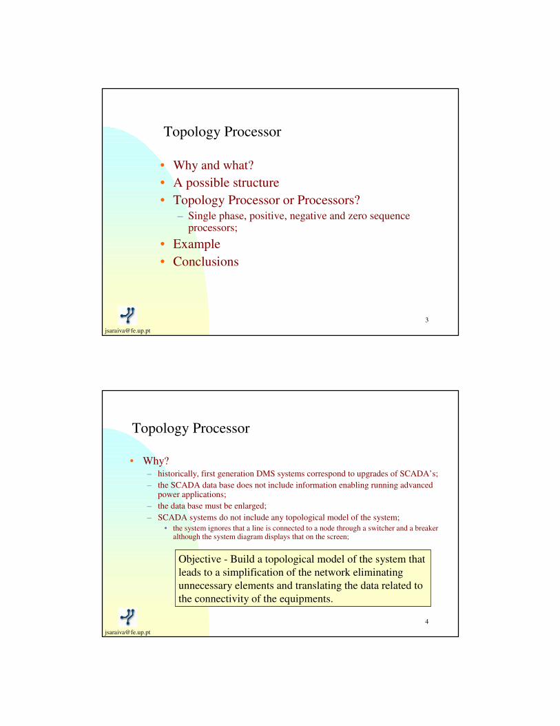
Topology Processor
• Why?– historically, first generation DMS systems correspond to upgrades of SCADA’s;
– the SCADA data base does not include information enabling running advanced power applications;
– the data base must be enlarged;
– SCADA systems do not include any topological model of the system;
• the system ignores that a line is connected to a node through a switcher and a breaker although the system diagram displays that on the screen;
Objective - Build a topological model of the system that
leads to a simplification of the network eliminating
unnecessary elements and translating the data related to
the connectivity of the equipments.
5
Topology Processor
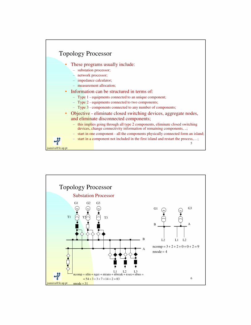
• These programs usually include:– substation processor;
– network processor;
– impedance calculator;
– measurement allocation;
• Information can be structured in terms of:– Type 1 - equipments connected to an unique component;
– Type 2 - equipments connected to two components;
– Type 3 - components connected to any number of components;
• Objective - eliminate closed switching devices, aggregate nodes, and eliminate disconnected components;– this implies going through all type 2 components, eliminate closed switching
devices, change connectivity information of remaining components, ..;
– start in one component - all the components physically connected form an island;
– start in a component not included in the first island and restart the process,…;
6
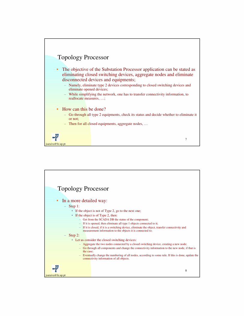
Topology Processor
31nnode
8321473354
nbussecnnbreakntransngernlinncomp
=
=+++++=
=+++++=
~ ~
L2 L1 L2
G1
B
G3
A
~ ~ ~
G1 G2 G3
T1 T2 T3
L1 L2 L3
B
A4nnode
9200223ncomp
=
=+++++=
Substation Processor
7
Topology Processor
• The objective of the Substation Processor application can be stated as eliminating closed switching devices, aggregate nodes and eliminate disconnected devices and equipments;– Namely, eliminate type 2 devices corresponding to closed switching devices and
eliminate opened devices;
– While simplifying the network, one has to transfer connectivity information, to reallocate measures, …;
• How can this be done?– Go through all type 2 equipments, check its status and decide whether to eliminate it
or not;
– Then for all closed equipments, aggregate nodes, …
8
Topology Processor
• In a more detailed way:– Step 1:
• If the object is not of Type 2, go to the next one;
• If the object is of Type 2, then:
– Get from the SCADA DB the status of the component;
– If it is opened, then eliminate all type 1 objects connected to it;
– If it is closed, if it is a switching device, eliminate the object, transfer connectivity and measurement information to the objects it is connected to;
– Step 2:
• Let us consider the closed switching devices:
– Aggregate the two nodes connected by a closed switching device, creating a new node;
– Go through all components and change the connectivity information to the new node, if that is the case;
– Eventually change the numbering of all nodes, according to some rule. If this is done, update the connectivity information of all objects.

9
Topology Processor
• Transmission Network Processor:– This module gathers the information received from the Substation Processor,
regarding each substation;
– It processes information regarding branches;
– The previous module treats branches as Type 1 devices (from the point of view of an isolated substation). Now the terminal nodes of the same line are gathered and they are created new information structures containing:
• Extreme nodes (among the ones coming from the simplified substation models);
• Parameters of the equivalent model of the component (overhead line, underground cable or transformer);
• Impedance calculator:– This module computes the parameters of the equivalent models of each component
(for instance for lines or transformers) using the corresponding input data;
• Measurement allocation:– This module allocates the measurements (currents, flows, voltages, …) to existing
elements in the simplified network.
10
Topology Processor
• Topology Processor or Processors?– The applications in the DMS have different requirements and use different
information:
• single line power flow uses a single phase model of the network;
• the symmetric three phase short circuit analysis uses the single phase model plus information about generators;
• asymmetric short circuit analysis requires the positive, negative and zero sequence models;
– Therefore it is usual to have the following modules;
• Single Phase Processor - event base updated - incremental approach;
• Positive Sequence Processor – run whenever required;
• Negative Sequence Processor – run whenever required;
• Zero Sequence Processor – run whenever required;
– this is the most demanding one;
11
Decomposition in symmetrical components
• Principle – any set of three asymmetrical phasors can be
decomposed in three sets of symmetrical phasors – a positive sequence, a negative sequence and a zero
sequence;
• Let us denote by:
– a, b and c the three phases;
– 0, 1 and 2 the zero, the positive and the negative sequences;
• Let , and be the original set of three phasors.
Then:aV bV cV
)2(c
)1(c
)0(cc
)2(b
)1(b
)0(bb
)2(a
)1(a
)0(aa
VVVV
VVVV
VVVV
++=
++=
++=
12
Decomposition in symmetrical components
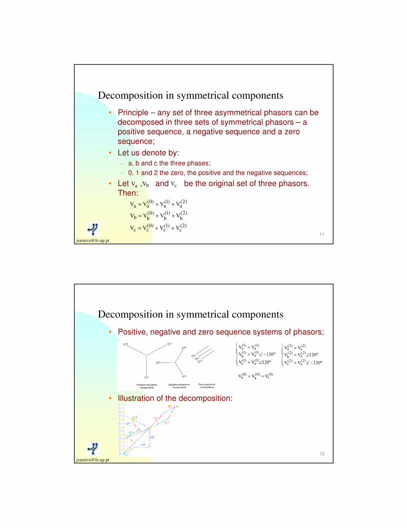
• Positive, negative and zero sequence systems of phasors;
• Illustration of the decomposition:
∠=
−∠=
=
o)1(a
)1(c
o)1(a
)1(b
)1(a
)1(a
120VV
120VV
VV
−∠=
∠=
=
o)2(a
)2(c
o)2(a
)2(b
)2(a
)2(a
120VV
120VV
VV
)0(c
)0(b
)0(a VVV ==
13
Decomposition in symmetrical components
• We also know that:
• In matrix form, this means:
)2(a
2)2(c
)2(a
)2(b
)1(a
)1(c
)1(a
2)1(b
)0(c
)0(b
)0(a
V.V
V.V
V.V
V.V
VVV
α=
α=
α=
α=
+=
oo2
o
)2(a
2)1(a
)0(ac
)2(a
)1(a
2)0(ab
)2(a
)1(a
)0(aa
12012401
1201
V.V.VV
V.V.VV
VVVV
−∠=∠=α
∠=α
α+α+=
α+α+=
++=
=
αα
αα=
)2(a
)1(a
)0(a
)2(a
)1(a
)0(a
2
2
c
b
a
V
V
V
.A
V
V
V
.
1
1
111
V
V
V
αα
αα=2
2
1
1
111
A
14
Decomposition in symmetrical components
• So, the symmetrical components can be calculated as:
• A similar result holds for currents:
=
αα
αα=
−
c
b
a1
c
b
a
2
2
)2(a
)1(a
)0(a
V
V
V
.A
V
V
V
.
1
1
111
.3
1
V
V
V
αα
αα=−
2
21
1
1
111
.3
1A
=
αα
αα=
−
c
b
a1
c
b
a
2
2
)2(a
)1(a
)0(a
I
I
I
.A
I
I
I
.
1
1
111
.3
1
I
I
I( )
( )
( )
α+α+=
α+α+=
++=
cb2
a)2(
a
c2
ba)1(
a
cba)0(
a
I.I.I.3
1I
I.I.I.3
1I
III.3
1I
15
Decomposition in symmetrical components
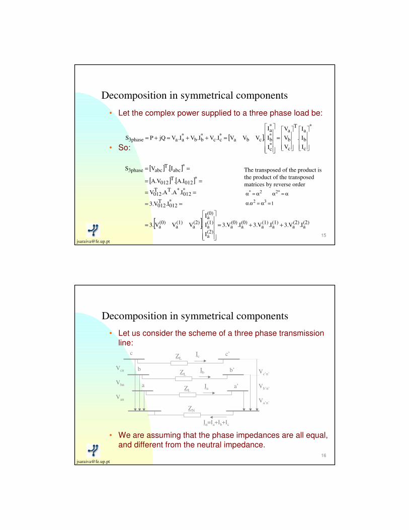
• Let the complex power supplied to a three phase load be:
• So:
[ ]
*
c
b
aT
c
b
a
*c
*b
*a
cba*cc
*bb
*aaphase3
I
I
I
.
V
V
V
I
I
I
.VVVI.VI.VI.VjQPS
=
=++=+=
[ ] [ ]
[ ] [ ]
[ ] (2)a
(2)a
(1)a
(1)a
(0)a
(0)a
(2)a
(1)a
(0)a
(2)a
(1)a
(0)a
*012
T012
*012
*TT012
*012
T012
*abc
Tabcphase3
I.V.3I.V.3I.V.3
I
I
I
.VVV3.
I.V3.
I.A.A.V
I.A.V.A
I.VS
++=
=
==
==
==
== The transposed of the product is
the product of the transposed
matrices by reverse order
1.
32
*22*
=α=αα
α=αα=α
16
Decomposition in symmetrical components
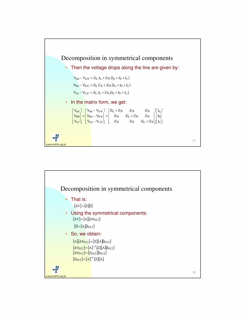
• Let us consider the scheme of a three phase transmission
line:
• We are assuming that the phase impedances are all equal, and different from the neutral impedance.
ZLIc
c c’
ZLIb
b b’
ZLIa
a a’
ZN
In=Ia+Ib+Ic
Vcn
Vbn
Van
Vc’n’
Vb’n’
Va’n’
17
Decomposition in symmetrical components
• Then the voltage drops along the line are given by:
• In the matrix form, we get:
( )cbaNcL'n'ccn III.ZI.ZVV +++=−
( )cbaNbL'n'bbn III.ZC.ZVV +++=−
( )cbaNaL'n'aan III.ZI.ZVV +++=−
+
+
+
=
−
−
−
=
c
b
a
NLNN
NNLN
NNNL
'n'ccn
'n'bbn
'n'ana
'cc
'bb
'aa
I
I
I
.
ZZZZ
ZZZZ
ZZZZ
VV
VV
VV
V
V
V
18
Decomposition in symmetrical components
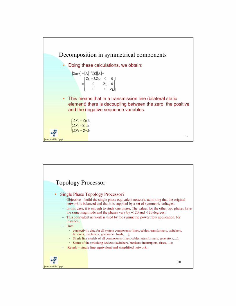
• That is:
• Using the symmetrical components:
• So, we obtain:
[ ] [ ][ ]I.ZV =∆
[ ] [ ][ ]012V.AV ∆=∆
[ ] [ ][ ]012I.AI =
[ ][ ] [ ][ ][ ]
[ ] [ ] [ ][ ][ ][ ] [ ][ ]
[ ] [ ] [ ][ ]A.Z.AZ
I.ZV
IA.Z.AV
IA.ZV.A
1012
012012012
0121
012
012012
−
−
=
=∆
=∆
=∆
19
Decomposition in symmetrical components
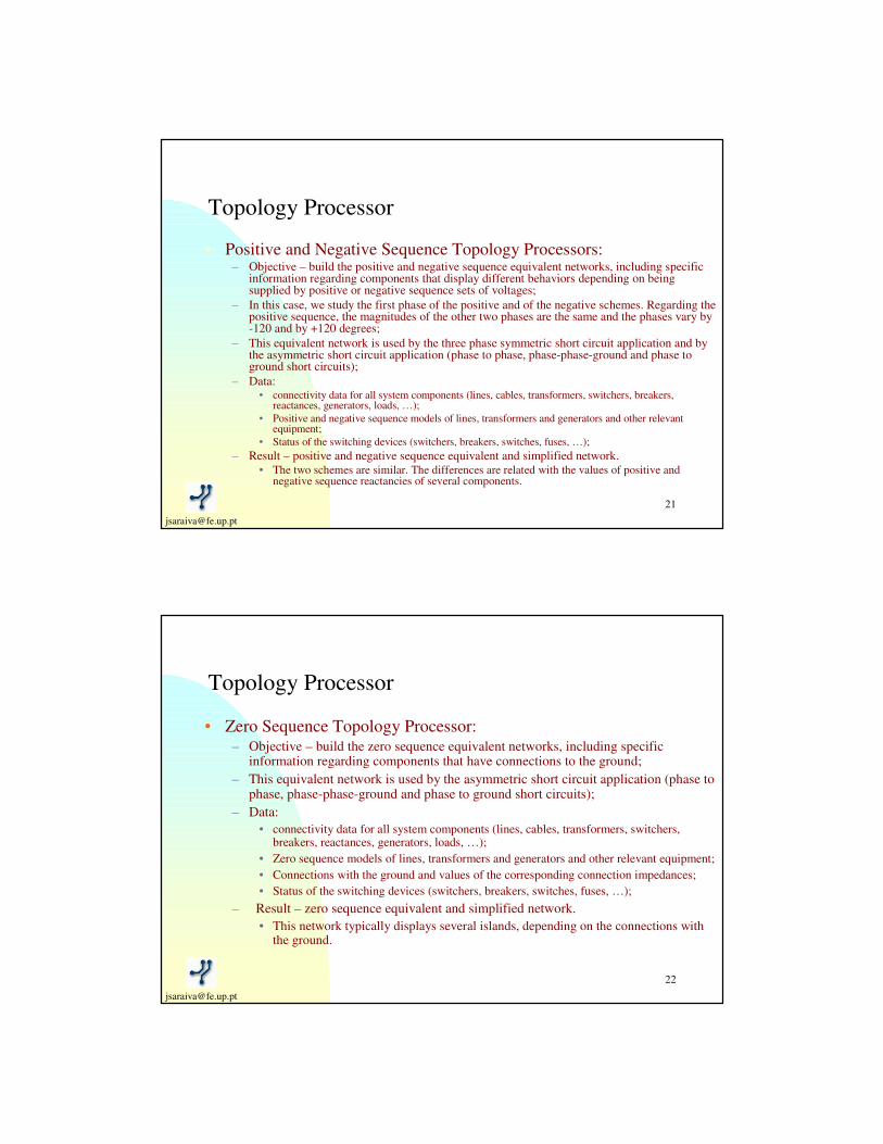
• Doing these calculations, we obtain:
• This means that in a transmission line (bilateral static element) there is decoupling between the zero, the positive
and the negative sequence variables.
[ ] [ ] [ ][ ]
+
=
==−
L
L
NL
1012
Z00
0Z0
00Z.3Z
A.Z.AZ
=∆
=∆
=∆
222
111
000
I.ZV
I.ZV
I.ZV
20
Topology Processor
• Single Phase Topology Processor?– Objective – build the single phase equivalent network, admitting that the original
network is balanced and that it is supplied by a set of symmetric voltages;
– In this case, it is enough to study one phase. The values for the other two phases have the same magnitude and the phases vary by +120 and -120 degrees;
– This equivalent network is used by the symmetric power flow application, for instance;
– Data:
• connectivity data for all system components (lines, cables, transformers, switchers, breakers, reactances, generators, loads, …);
• Single line models of all components (lines, cables, transformers, generators,…);
• Status of the switching devices (switchers, breakers, interruptors, fuses, …);
– Result – single line equivalent and simplified network.
21
Topology Processor
• Positive and Negative Sequence Topology Processors:– Objective – build the positive and negative sequence equivalent networks, including specific
information regarding components that display different behaviors depending on being supplied by positive or negative sequence sets of voltages;
– In this case, we study the first phase of the positive and of the negative schemes. Regarding the positive sequence, the magnitudes of the other two phases are the same and the phases vary by -120 and by +120 degrees;
– This equivalent network is used by the three phase symmetric short circuit application and by the asymmetric short circuit application (phase to phase, phase-phase-ground and phase to ground short circuits);
– Data:• connectivity data for all system components (lines, cables, transformers, switchers, breakers,
reactances, generators, loads, …);
• Positive and negative sequence models of lines, transformers and generators and other relevant equipment;
• Status of the switching devices (switchers, breakers, switches, fuses, …);
– Result – positive and negative sequence equivalent and simplified network.• The two schemes are similar. The differences are related with the values of positive and
negative sequence reactancies of several components.
22
Topology Processor
• Zero Sequence Topology Processor:– Objective – build the zero sequence equivalent networks, including specific
information regarding components that have connections to the ground;
– This equivalent network is used by the asymmetric short circuit application (phase to phase, phase-phase-ground and phase to ground short circuits);
– Data:
• connectivity data for all system components (lines, cables, transformers, switchers, breakers, reactances, generators, loads, …);
• Zero sequence models of lines, transformers and generators and other relevant equipment;
• Connections with the ground and values of the corresponding connection impedances;
• Status of the switching devices (switchers, breakers, switches, fuses, …);
– Result – zero sequence equivalent and simplified network.
• This network typically displays several islands, depending on the connections with the ground.
23
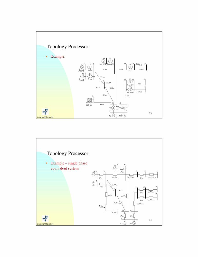
Topology Processor
• Example:
A3 A4
A1
A2
A5 T5
T2
T1
T6
T7
T8
T3 T4
network
220 kV
jxN16
1
2
3
4
7
8
9 10
11 1213
14
20 km
30 km
25 km
30 km 60 km
40 km
15 km
20 km 10 km
5 km
10 km
220 kV
1715 16
24
Topology Processor
• Example – single phase
equivalent system5 6
A3 A4
A1
A2
A5
jxT5
jxT2
jxT1
jxT6
jxT7
jxT8
jxT3 jxT4
1
2
3
4
7
8
9 10
11 1213
14
r2-6+jx2-6
r2-7+jx2-7
r7-9+jx7-9
r1-2+jx1-2 r6-9+jx6-9
r1-9+jx1-9
r10-11+jx10-11
r6-15+jx6-15 r16-17+jx16-17
r12-13+jx12-
13
r12-14+jx12-14
220 kV
1715 16
P+jQ
25
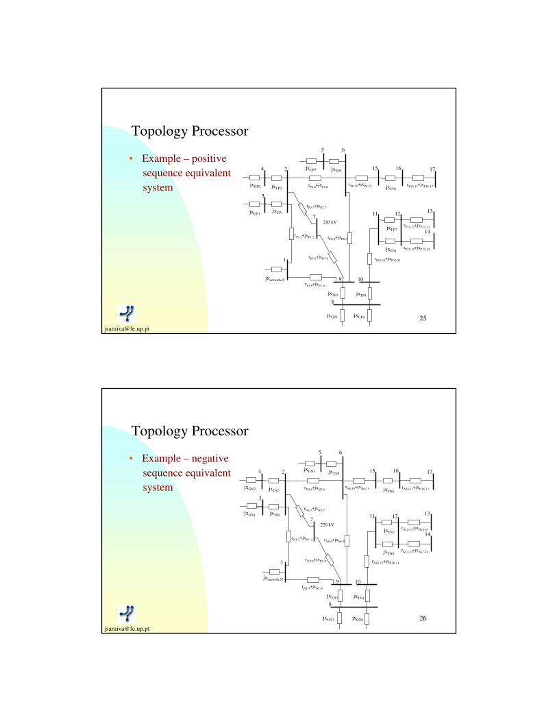
Topology Processor
• Example – positive
sequence equivalent
system
14
5 6
jxGP3 jxGP4
jxGP1
jxGP2
jxGP5 jxTP5
jxTP2
jxTP1
jxTP6
jxTP7
jxTP8
jxTP3 jxTP4
1
2
3
4
7
8
9 10
11 1213
rP2-6+jxP2-6
rP2-7+jxP2-7
rP7-9+jxP7-9
rP1-2+jxP1-2 rP6-9+jxP6-9
rP1-9+jxP1-9
rP10-11+jxP10-11
rP6-15+jxP6-15 rP16-17+jxP16-17
rP12-13+jxP12-13
rP12-14+jxP12-14
220 kV
1715 16
jxnetwork,P
26
Topology Processor
• Example – negative
sequence equivalent
system
5 6
jxGN3 jxGN4
jxGN1
jxGN2
jxGN3 jxTN5
jxTN2
jxTN1
jxTN6
jxTN7
jxTN8
jxTN3 jxTN4
1
2
3
4
7
8
9 10
11 1213
14
rN2-6+jxN2-6
rN2-7+jxN2-7
rN7-9+jxN7-9
rN1-2+jxN1-2 rN6-9+jxN6-9
rN1-9+jxN1-9
rN10-11+jxN10-11
rN6-15+jxN6-15 rN16-17+jxN16-17
rN12-13+jxN12-13
rN12-14+jxN12-14
220 kV
1715 16
jxnetwork,N
27
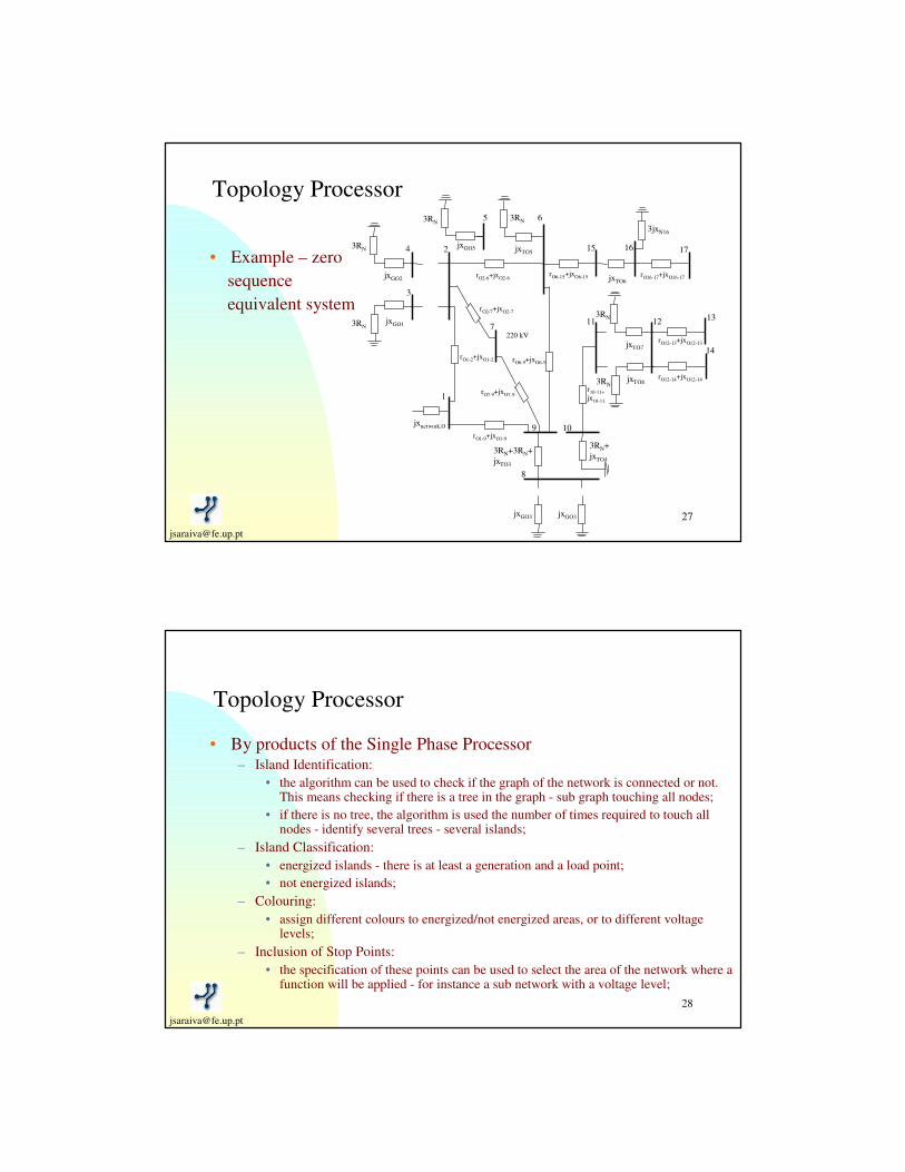
Topology Processor
• Example – zero
sequence
equivalent system
5 3RN 6
jxGO3 jxGO3
jxGO1
jxGO2
jxGO5 jxTO5
jxTO6
jxTO7
jxTO8
3RN+3RN+
jxTO3
3RN+
jxTO4
1
2
3
4
7
8
9 10
11 1213
14
rO2-6+jxO2-6
rO2-7+jxO2-7
rO7-9+jxO7-9
rO1-2+jxO1-2 rO6-9+jxO6-9
rO1-9+jxO1-9
r10-11+
jx10-11
rO6-15+jxO6-15 rO16-17+jxO16-17
rO12-13+jxO12-13
rO12-14+jxO12-14
220 kV
1715 16
jxnetwork,O
3RN
3RN
3RN
3RN
3RN
3jxN16
28
Topology Processor
• By products of the Single Phase Processor– Island Identification:
• the algorithm can be used to check if the graph of the network is connected or not. This means checking if there is a tree in the graph - sub graph touching all nodes;
• if there is no tree, the algorithm is used the number of times required to touch all nodes - identify several trees - several islands;
– Island Classification:
• energized islands - there is at least a generation and a load point;
• not energized islands;
– Colouring:
• assign different colours to energized/not energized areas, or to different voltage levels;
– Inclusion of Stop Points:
• the specification of these points can be used to select the area of the network where a function will be applied - for instance a sub network with a voltage level;
29
Topology Processor
• By products of the Single Phase Processor– Tracing:
• Galvanic Tracing - once a point is specified, it identifies all components connected by non-magnetic connections to the specified point;
• Tracing Upstream - once a point is specified, one aims at identifying all possible paths that interconnect that point to generation nodes or to interconnections to other networks;
• Tracing Downstream - once a point is specified, one aims at identifying all possible paths that interconnect that point to system loads;
• Tracing between two points - it identifies all paths connecting those two points;
– Connection of a point to earth - tracing to earth:
• after specifying a point, this function checks if this point is in an island identified by the single phase processor where there is at least one connection to earth;
30
Conclusions
• The topology processor is an essential application if one wants to upgrade a traditional SCADA system to a DMS;
• It builds a topological equivalent system of the real one, based on digital measurements;
• It simplifies the network, leading to a manageable equivalent system;
• It is run in a cyclic way, or whenever there is a topology change or an event that triggers this application;
• This triggering event can correspond to another application itself that requires an updated topology equivalent;
• Some specific applications require the single phase Topology Processor. Others require the positive, negative and zero-sequence equivalents;
• The most efficient implementation is an incremental one – departing from the existing network, check the impact that a topology change has on the system;– In general this impact is well located and limited – increased efficiency.