Embed Size (px)
Citation preview
1
EEM 483 POWER SYSTEMS ANALYSIS – II LABORATORY
EXPERIMENT #1: ALTERNATOR AND PARALLEL OPERATION
Experiment 1-A
NO-LOAD TEST
Objectives:
Determining the mechanical and iron losses of the alternator.
Recording the open-circuit curve at various speeds.
Equipment:
1 DL1013T2 DC filtered power supply
1 DL1023PS Shunt dc drive motor
1 DL 1026A Three-phase alternator
1 DL 2025 DT Speed indicator
1 DL 2031 Optical electronic generator
1 DL 2108T01 Excitation voltage controller
2 DL 2109T1A Moving-iron ammeter (1000 mA)
1 DL 2109T1PV Moving-iron voltmeter (600 V)
Note: Mount the DL 2031 optical electronic generator on the dc motor shaft end.
Fig. 1. No-load test
2
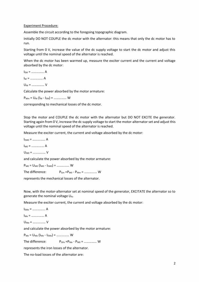
Experiment Procedure:
Assemble the circuit according to the foregoing topographic diagram.
Initially DO NOT COUPLE the dc motor with the alternator: this means that only the dc motor has to run.
Starting from 0 V, increase the value of the dc supply voltage to start the dc motor and adjust this voltage until the nominal speed of the alternator is reached.
When the dc motor has been warmed up, measure the exciter current and the current and voltage absorbed by the dc motor:
IEM = …………… A
IM = …………… A
UM = …………… V
Calculate the power absorbed by the motor armature:
PMm = UM (IM - IEM) = …………… W
corresponding to mechanical losses of the dc motor.
Stop the motor and COUPLE the dc motor with the alternator but DO NOT EXCITE the generator. Starting again from 0 V, increase the dc supply voltage to start the motor-alternator set and adjust this voltage until the nominal speed of the alternator is reached.
Measure the exciter current, the current and voltage absorbed by the dc motor:
IEM0 = …………… A
IM0 = …………… A
UM0 = …………… V
and calculate the power absorbed by the motor armature:
PM0 = UM0 (IM0 - IEM0) = …………… W
The difference: PGm =PM0 - PMm = …………… W
represents the mechanical losses of the alternator.
Now, with the motor-alternator set at nominal speed of the generator, EXCITATE the alternator so to generate the nominal voltage UN.
Measure the exciter current, the current and voltage absorbed by the dc motor:
IEMe = …………… A
IMe = …………… A
UMe = …………… V
and calculate the power absorbed by the motor armature:
PMe = UMe (IMe - IEMe) = …………… W
The difference: PGFe =PMe - PM0 = …………… W
represents the iron losses of the alternator.
The no-load losses of the alternator are:
3
PG0 =PGm + PGFe = …………… W
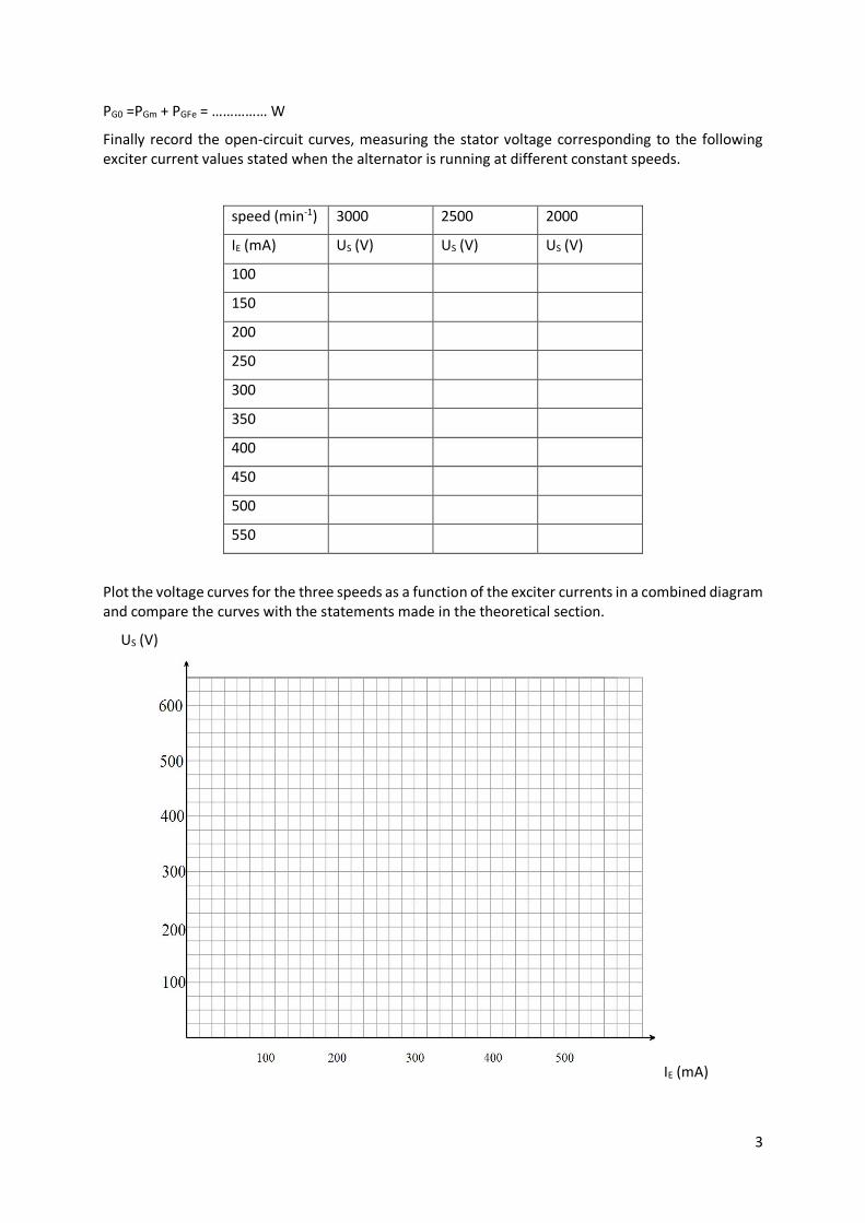
Finally record the open-circuit curves, measuring the stator voltage corresponding to the following exciter current values stated when the alternator is running at different constant speeds.
speed (min-1) 3000 2500 2000
IE (mA) US (V) US (V) US (V)
100
150
200
250
300
350
400
450
500
550
Plot the voltage curves for the three speeds as a function of the exciter currents in a combined diagram and compare the curves with the statements made in the theoretical section.
US (V)
IE (mA)
4
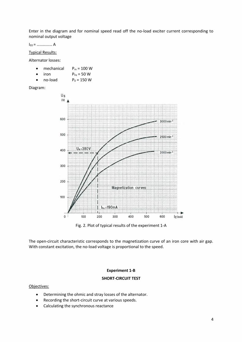
Enter in the diagram and for nominal speed read off the no-load exciter current corresponding to nominal output voltage
IE0 = …………… A
Typical Results:
Alternator losses:
mechanical Pm = 100 W
iron PFe = 50 W
no-load P0 = 150 W
Diagram:
Fig. 2. Plot of typical results of the experiment 1-A
The open-circuit characteristic corresponds to the magnetization curve of an iron core with air gap. With constant excitation, the no-load voltage is proportional to the speed.
Experiment 1-B
SHORT-CIRCUIT TEST
Objectives:
Determining the ohmic and stray losses of the alternator.
Recording the short-circuit curve at various speeds.
Calculating the synchronous reactance
5
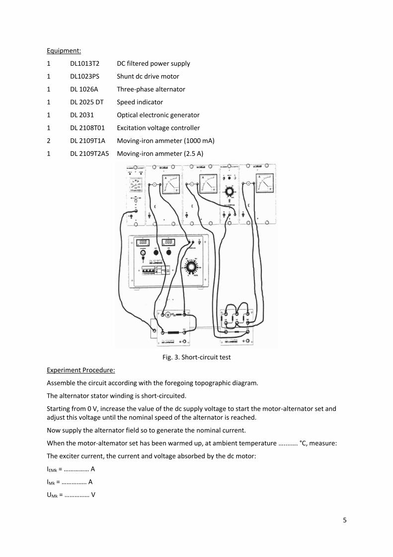
Equipment:
1 DL1013T2 DC filtered power supply
1 DL1023PS Shunt dc drive motor
1 DL 1026A Three-phase alternator
1 DL 2025 DT Speed indicator
1 DL 2031 Optical electronic generator
1 DL 2108T01 Excitation voltage controller
2 DL 2109T1A Moving-iron ammeter (1000 mA)
1 DL 2109T2A5 Moving-iron ammeter (2.5 A)
Fig. 3. Short-circuit test
Experiment Procedure:
Assemble the circuit according with the foregoing topographic diagram.
The alternator stator winding is short-circuited.
Starting from 0 V, increase the value of the dc supply voltage to start the motor-alternator set and adjust this voltage until the nominal speed of the alternator is reached.
Now supply the alternator field so to generate the nominal current.
When the motor-altemator set has been warmed up, at ambient temperature …....…. °C, measure:
The exciter current, the current and voltage absorbed by the dc motor:
IEMk = …………… A
IMk = …………… A
UMk = …………… V
6
and calculate the power absorbed by the armature motor:
PMk = UMk (IMk - IEMk) = …………… W
the exciter current of the generator at nominal short-circuit stator current:
IEk = …………… A
The short-circuited alternator absorbs the power:
PGk =PMk - PMm = …………… W
where PMm is the dc motor mechanical loss (see experiment 1-A).
The difference:
PCu =PGk - PGm = …………… W
where PGm are the alternator mechanical losses (see experiment 1-A), represents the copper losses of the alternator.
Since at ambient temperature, the stator ohmic losses are:
PSCu = 3 RS IN2 = …………… W
we can calculate the stray losses:
Pad =PGCu - PSCu = …………… W
and the pertinent equivalent resistance:
Rad = Pad / IN2 = …………… Ω
In order to calculate the copper losses at conventional temperature of 75 oC, the stator total equivalent resistance is introduced:
R75 = 3 RS75 + Rad = …………… Ω
and so:
PCu75 = R75 IN2 = …………… W
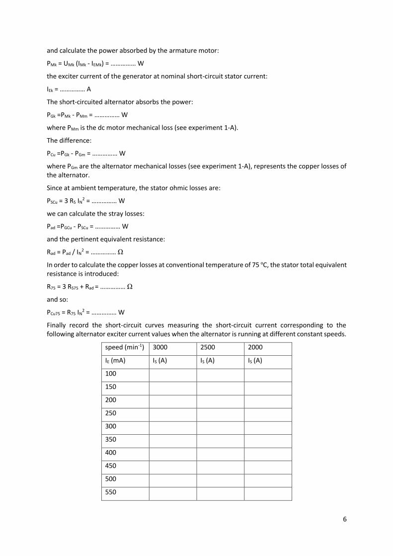
Finally record the short-circuit curves measuring the short-circuit current corresponding to the following alternator exciter current values when the alternator is running at different constant speeds.
speed (min-1) 3000 2500 2000
IE (mA) IS (A) IS (A) IS (A)
100
150
200
250
300
350
400
450
500
550
7
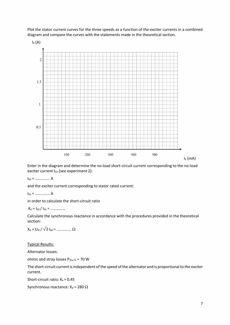
Plot the stator current curves for the three speeds as a function of the exciter currents in a combined diagram and compare the curves with the statements made in the theoretical section.
IS (A)
IE (mA)
Enter in the diagram and determine the no-load short-circuit current corresponding to the no-load exciter current IEO (see experiment 2):
Ik0 = …………… A
and the exciter current corresponding to stator rated current:
IEk = …………… A
in order to calculate the short-circuit ratio
Kk = IE0 / IEk = ……………
Calculate the synchronous reactance in accordance with the procedures provided in the theoretical section:
Xd = UN / √3 Ik0 = …………… Ω
Typical Results:
Alternator losses:
ohmic and stray losses PSCu75 = 70 W
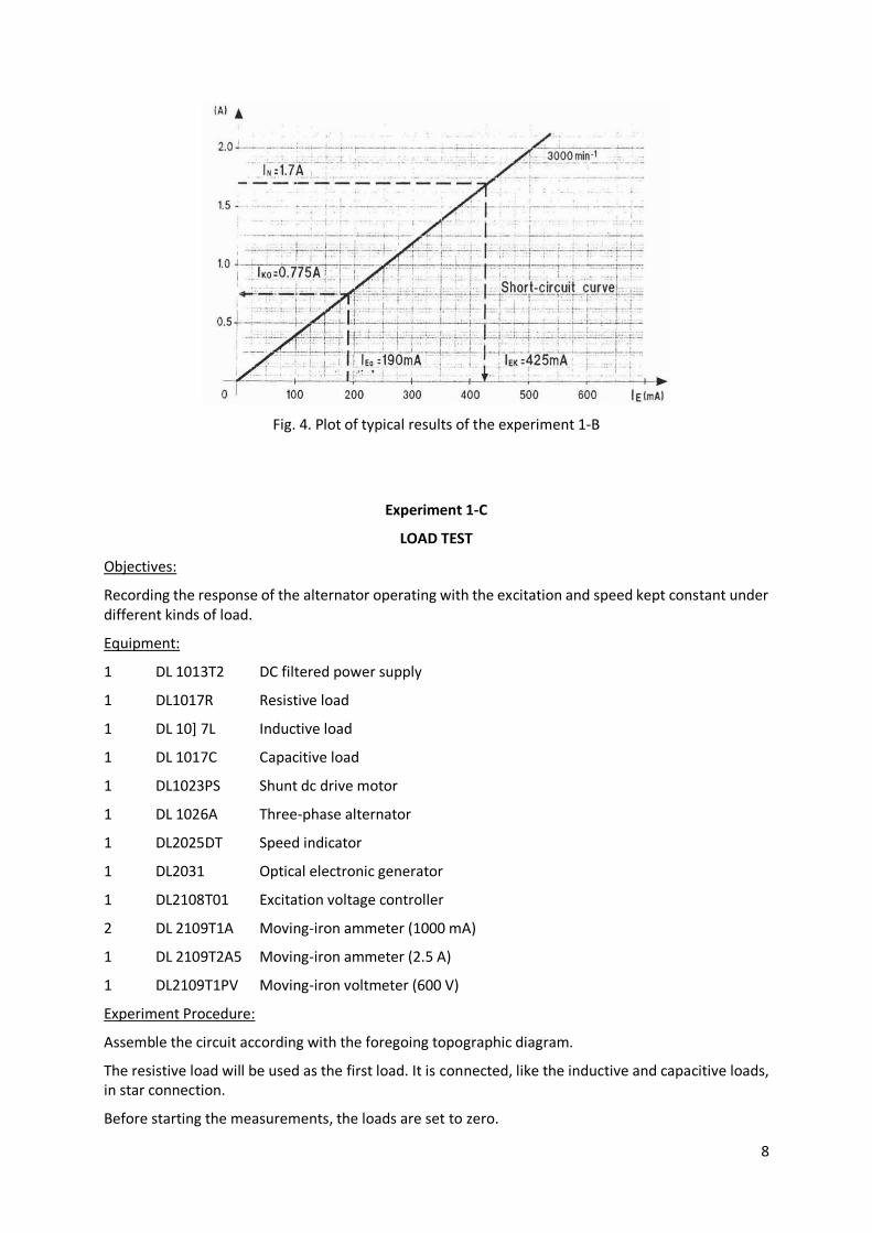
The short-circuit current is independent of the speed of the alternator and is proportional to the exciter current.
Short-circuit ratio: Kk = 0.45
Synchronous reactance: Xd = 280 Ω
8
Fig. 4. Plot of typical results of the experiment 1-B
Experiment 1-C
LOAD TEST
Objectives:
Recording the response of the alternator operating with the excitation and speed kept constant under different kinds of load.
Equipment:
1 DL 1013T2 DC filtered power supply
1 DL1017R Resistive load
1 DL 10] 7L Inductive load
1 DL 1017C Capacitive load
1 DL1023PS Shunt dc drive motor
1 DL 1026A Three-phase alternator
1 DL2025DT Speed indicator
1 DL2031 Optical electronic generator
1 DL2108T01 Excitation voltage controller
2 DL 2109T1A Moving-iron ammeter (1000 mA)
1 DL 2109T2A5 Moving-iron ammeter (2.5 A)
1 DL2109T1PV Moving-iron voltmeter (600 V)
Experiment Procedure:
Assemble the circuit according with the foregoing topographic diagram.
The resistive load will be used as the first load. It is connected, like the inductive and capacitive loads, in star connection.
Before starting the measurements, the loads are set to zero.

9
Fig. 5. Load test
Starting from 0 V, increase the value of the dc supply voltage to start the motor-alternator set and adjust this voltage until the nominal speed of the alternator is reached.
Supply the alternator field with the no-load exciter current IEO (see experiment 2) and then maintained for all measurements.
When the motor-alternator set has been warmed up, beginning from R1 value reduce the resistive load in steps till the R5 value.
For each step measure the stator current and voltage and enter the measured values in the following table.
n=………….…… min-1 IE0=……………… mA
R IS (A) US (V) L IS (A) US (V) C IS (A) US (V)
R1 L1 C1
R2 L2 C2
R3 L3 C3
R4 L4 C4
R5 L5 C5
After the de-excitation of the alternator, the resistive load is replaced by the inductive load and the above measurement is repeated in the same fashion for the indicated inductive values.
Again after the de-excitation of the alternator the inductive load is replaced by the capacitive load and the above measurement is repeated in the same fashion for the indicated capacitive values.
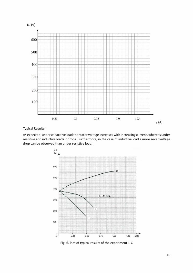
For the three types of load plot the stator voltages as a function of the stator current in a combined diagram and compare the results with the information provided in the theoretical section.
10
US (V)
IS (A)
Typical Results:
As expected, under capacitive load the stator voltage increases with increasing current, whereas under resistive and inductive loads it drops. Furthermore, in the case of inductive load a more sever voltage drop can be observed than under resistive load.
Fig. 6. Plot of typical results of the experiment 1-C