Embed Size (px)
Citation preview

This project has received funding from the European Union Seventh Framework Programme
under grant agreement n° 609349.
OPTIMISED DESIGN METHODOLOGIES FOR ENERGY-EFFICIENT
BUILDINGS INTEGRATED IN THE NEIGHBOURHOOD ENERGY SYSTEMS
eeEmbedded – D4.1 BIM Multi-Model
Responsible Authors:
Marc Mosch, Jens Kaiser
Co-Authors:
Francisco Forns-Samso , Romy Guruz, Peter Katranuschkov, Tuomas Laine, Klaus
Linhard, Eko Nityantoro, Theodora Pappou, Hervé Pruvost, Thrasos Rekouniotis,
Raphael Schär, Kenneth Solvik, Pit Stenzel, Amrita Sukumar, Arne Tøn, Raimund Zellner.
Due date: 31.03.2015
Issue date: 31.03.2015
Nature: Other
Coordinator: R.J. Scherer, Institute for Construction Informatics, Technische Universität Dresden, Germany

D4.1 BIM Multi-Model, Multi-Physics Models and Management Methods
Version 1.3
Page 2/58
© eeEmbedded Consortium www.eeEmbedded.eu
Start date of project: 01.10.2013 Duration: 48 months
Organisation name of lead contractor for this deliverable:
Technische Universität Dresden CIB
History
Version
Description Lead Author Date
0.1 Example: Deliverable Structure Mosch, Guruz, Katranuschkov (CIB)
28.10.2014
0.2 Categorization initial input Forns-Samso (GRA), Solvik (DDS), Stenzel (EAS), Tøn (EPM), Mosch (CIB), Guruz (CIB)
14.01.2015
0.2 Classification Introduction Mosch (CIB) 25.02.2015
0.3 Content Categorization Kaiser (IET), Stenzel (EAS), Sukumar (RIB), Pruvost, Mosch (CIB)
26.02.2015
0.4 Input Categorization and Classification
Kaiser (IET), Stenzel (EAS), Sukumar(RIB)
27.02.2015
0.5 Input Categorization and Classification
Kaiser (IET), Stenzel (EAS), Sukumar (RIB)), Pappou, Rekouniotis (SOF), Pruvost, Mosch (CIB)
02.03.2015
0.6 Input Multi Model Nityantoro, Mosch (CIB) 06.03.2015 0.7 Reorganization, Introduction,
Multi Model Mosch (CIB) 09.03.2015
0.8 Additional Categorization Zellner (NEM), Pappou, Rekouniotis (SOF), Solvik (DDS), Forns-Samso (GRA), Mosch (CIB)
10.03.2015
0.9 Revision Zellner (NEM), Solvik (DDS), Stenzel (EAS), Schär (SAR), Rekouniotis (SOF), Tøn (EPM), Forns-Samso (GRA), Mosch (CIB)
18.03.2015
1.0 Revision, Proof Reading Mosch (CIB) 23.03.2015
1.1 Revision, Prefinal Check, Proof Reading
Kaiser (IET), Stenzel (EAS), Schär (SAR), Geißler (BAM), Guruz, Mosch (CIB)
25.03.2015
1.2 Corrections Zellner (NEM), Laine, Forns-Samso (GRA), Pappou, Rekouniotis (SOF), Walser (DDS), Kaiser(IET), Mosch (CIB)
27.03.2015
1.3 Final Revise and Proof Reading Mosch (CIB) 30.03.2015

D4.1 BIM Multi-Model, Multi-Physics Models and Management Methods
Version 1.3
Page 3/58
© eeEmbedded Consortium www.eeEmbedded.eu
Copyright
This report is © eeEmbedded Consortium 2015. Its duplication is restricted to the personal
use within the consortium, the funding agency and the project reviewers. Its duplication is
allowed in its integral form only for anyone's personal use for the purposes of research or
education.
Citation
Mosch, M. & Kaiser J. (2015); eeEmbedded D4.1: BIM Multi-Model, Multi-Physics Models and Management Methods, © eeEmbedded Consortium, Brussels. Acknowledgements
The work presented in this document has been conducted in the context of the seventh
framework programme of the European community project eeEmbedded (n° 609349).
eeEmbedded is a 48 month project that started in October 2013 and is funded by the European
Commission as well as by the industrial partners. Their support is gratefully appreciated. The
partners in the project are Technische Universität Dresden (Germany), Fraunhofer-Gesellschaft
zur Förderung der angewandten Forschung E.V (Germany), NEMETSCHEK Slovensko, S.R.O.
(Slovakia), Data Design System ASA (Norway), RIB Information Technologies AG (Germany), Jotne
EPM Technology AS (Norway), Granlund OY (Finland), SOFISTIK HELLAS AE (Greece), Institute for
applied Building Informatics IABI (Germany), FR. SAUTER AG (Switzerland), Obermeyer Planen +
Beraten (Germany), Centro de Estudios Materiales y Control de Obras S.A. (Spain), STRABAG AG
(Austria) and Koninklijke BAM Group NV (The Netherlands). This report owes to a collaborative
effort of the above organizations.
Project of SEVENTH FRAMEWORK PROGRAMME OF THE EUROPEAN COMMUNITY
Dissemination Level
PU Public X
PP Restricted to other programme participants (including the Commission Services)
RE Restricted to a group specified by the consortium (including the Commission
Services)
CO Confidential, only for members of the consortium (including the Commission
Services)

D4.1 BIM Multi-Model, Multi-Physics Models and Management Methods
Version 1.3
Page 4/58
© eeEmbedded Consortium www.eeEmbedded.eu
Abbreviations
BACS Building Automation and Control Systems
BAS Building Automation System
BCF BIM Collaboration Format
BEM Building Energy Modeling
BEPS Building Energy Performance Simulation
BIM Building Information Model
BoQ Bill of Quantities
CAD Computer Aided Design
CBS Cost Breakdown Structure
CFD Computational Fluid Dynamics
COBie Construction Operations Building Information Exchange
DACS District Automation and Control Systems
DGNB Deutsche Gewerkschaft für Nachhaltiges Bauen
DV Decision Value
eeE eeEmbedded
eeBIM Energy-efficient Building Information Model
eeeBIM Energy-efficient embedded Building Information Model
EN European Norm
ERP Enterprise Resource Planning
ES Energy Simulation
ESD Energy System Designer
ESIM Energy System Information Model
FSGIM Facility Smart Grid Information Model
gbXML Green Building Extended Markup Language
HVAC Heating Ventilation and Air Conditioning
IAI International Alliance for Interoperability
ID Identifier
IDF Intermediate Data Format
IDD Input Data Dictionary
IFC Industry Foundation Classes
IGES Initial Graphics Exchange Specification

D4.1 BIM Multi-Model, Multi-Physics Models and Management Methods
Version 1.3
Page 5/58
© eeEmbedded Consortium www.eeEmbedded.eu
ISO International Organization for Standardization
KDP Key Design Parameter
KP Key Point
KPI Key Performance Indicator
LCA Life Cycle Assessment
LCC Life Cycle Costing
LoD Level of Detail
MEP Mechanical, Electrical & Plumbing
MMC Multi-Model Container
m2m Model to model
MVD Model View Definition
MVS Model View Definition
P&ID Piping and Instrumentation Diagram/Drawing
RA Room Automation
SGAM Smart Grid Architecture Model
SPF Step Physical File
SysML Systems Modeling Language
tbd to be defined
TEB Thermal Energy Building Simulation
TES Thermal Energy System Simulation
TMY Typical Meteorological Year
TRY Test Reference Year
UML Unified Modeling Language
VDI Verein Deutscher Ingenieure
VRV Variable Refrigerant Volume
vtk Visualization Toolkit
XMI XML Metadata Interchange
XML Extensible Markup Language

D4.1 BIM Multi-Model, Multi-Physics Models and Management Methods
Version 1.3
Page 6/58
© eeEmbedded Consortium www.eeEmbedded.eu
TABLE OF CONTENTS
Executive Summary __________________________________________________________________ 7
1 The eeE Multi-Model Approach ____________________________________________________ 8
1.1 General Multi-Model Approach _______________________________________________ 8
1.2 Link Model ________________________________________________________________ 8
1.3 Multi-Model Specialisation ___________________________________________________ 8
1.4 Multi-Model Container ______________________________________________________ 9
2 Model Categorisation ___________________________________________________________11
2.1 Organisational Concepts and Models __________________________________________11
2.2 Physical Data Models _______________________________________________________12
2.3 Analysis Information Data Models ____________________________________________13
2.4 Uncertainty Information Models _____________________________________________17
3 Domain Data Model Classification _________________________________________________18
3.1 Architectural Models _______________________________________________________26
3.2 ESIM Models _____________________________________________________________28
3.3 HVAC Models _____________________________________________________________34
3.4 BACS Models _____________________________________________________________36
3.5 FM Models _______________________________________________________________40
3.6 Climate Models ___________________________________________________________42
3.7 Simulation Models _________________________________________________________44
3.8 LCC Models_______________________________________________________________48
3.9 LCA Models ______________________________________________________________50
3.10 Uncertainty Information Models _____________________________________________52
3.11 Decision Making Support Models _____________________________________________54
Conclusions _____________________________________________ Fehler! Textmarke nicht definiert.
References ________________________________________________________________________57

D4.1 BIM Multi-Model, Multi-Physics Models and Management Methods
Version 1.3
Page 7/58
© eeEmbedded Consortium www.eeEmbedded.eu
Executive Summary
The objective of Deliverable 4.1 “BIM Multi-Model, Multi-Physics Models and Management
Methods” is to define the relevant domain models in the eeE context as a baseline for the
interoperability methods and the ontology to be developed in WP5. This includes the
categorisation and the classification of those models as well as a brief recapitulation of the Multi-
Model approach for their exchange.
D4.1 is structured into 4 chapters:
In the first chapter the Multi-Model approach is outlined, followed by a definition of the according Link Model, a discourse about the Multi-Model specialisation as well as the Multi-Model Container.
In the second chapter the categorization of the domain models relevant in the eeE project is elaborated. The categorization is four-part. It partitions the domain models into organisational concepts and models, physical data models, analysis information models and uncertainty information models.
The third chapter features the domain model classification. It is subdivided into one sub-chapter for each domain in the eeE context, namely architectural, ESIM, BACS, HVAC, FM, simulation, LCC, LCA and decision making models. In addition climate and uncertainty information models relevant for analysis related domains (SIM, LCC and LCA) are discussed.
CIB, DDS, EAS, EPM, GRA, IET, IAB, NEM, RIB, SAR and SOF were involved and each of those
partners contributed according to the individual expertise as follows:
The deliverable was led by CIB. The content of this deliverable was elaborated and discussed in
frequent web conferences between all above mentioned partners. CIB was leading discussions
and has contributed in all tasks.
CIB: all tasks, deliverable elaboration, content of chapter 1, input chapters 2 and 3, editing
EAS, RIB, SOF, IET: input chapter 2 and 3
DDS, EPM, GRA, NEM, SAR: input chapter 3
IAB: discussion and advices

D4.1 BIM Multi-Model, Multi-Physics Models and Management Methods
Version 1.3
Page 8/58
© eeEmbedded Consortium www.eeEmbedded.eu
1 The eeE Multi-Model Approach
For the exchange of the domain models categorized and classified in chapters 2 and 3 the so
called Multi-Model approach was chosen. The term Multi-Model describes the combination of
multiple related models from different domains which are in this context referred to as
elementary models. The underlying idea is to combine both engineering and management models
in a single information resource to achieve a closely linked cooperation between the different
domains of the construction industry. The elementary models in the container are interconnected
via one or more link models. The result is a consistent Multi-Model that represents a certain
status of a project. The Multi-Model concept was initially presented in chapter 3.4 of D1.3
(Calleja-Rodriguez & Guruz, 2014). In the following a short recapitulation will be given, which
serves as an introduction to the subsequent deliverables of WP4.
1.1 General Multi-Model Approach
The Multi-Model approach for example presented in (Fuchs & Nityantoro, 2013) and (Scherer &
Schapke, 2014) is based on Multi-Model Containers (MMCs). These containers primarily consist of
elementary models, which can be any kind of either engineering or management models. Those
models are for example represented by IFC files, for the exchange of Building Information Models
(BIM) or by GAEBXML1 (German Joint Committee for Electronics in Construction), a standard for
construction information exchanged during construction bidding, contracting and invoicing as well
as during construction. A Multi-Model Container consists of a 3D building model and calculated
quantities deduced from its elements as well as link models which allow connecting those values
with the elements.
1.2 Link Model
Besides the linking of elementary models as part of the Multi-Model Container so-called Link
Models connect elements of different elementary models via unique identifiers (IDs). The
underlying general concept for the link model which was developed in the Mefisto project will be
used as baseline for interlinking the BIM domain models with other models, like climate and user
behaviour models, BACS and ESIM in the upcoming D4.3.
1.3 Multi-Model Specialisation
The metadata of the Multi-Model as well as that of elementary and link models facilitate a
substantive conclusions and offer information about the resources without the necessity to open
all involved files.
This enables the parent use of the data to manage numerous Multi-Models in a construction
project. Within a collaboration management platform, it is possible to specialise a Multi-Model
based on the current task, domain, as well as on the users role.
Metadata is not only a qualitative description of data but also considered to be representative for
the actual models even if they do not exist yet. This concept allows defining tasks in the building
information process by creating so called Multi-Model Templates. These are kind of blueprints –

D4.1 BIM Multi-Model, Multi-Physics Models and Management Methods
Version 1.3
Page 9/58
© eeEmbedded Consortium www.eeEmbedded.eu
containers potentially missing some required elementary models, which are represented by a
metadata-based to-be description.
The expected elementary models might be part of one or several existing Multi-Models. In the
first case the Multi-Model can be reused. In the second case (depicted in Figure 1) the Multi-
models which come into question have to be decomposed, reorganized and merged for the given
task. Assumed not all requested elementary models can be found in existing Multi-Models the
new Multi-Model will again contain only metadata describing the missing elementary model,
which then has to be added in another way.
This combination and merging of Multi-Models will be discussed in more detail in D4.4 under the
general term Multi-Model Manipulation which also includes the transformation, mapping,
structural changing and filtering of models. The later manipulation is then taken up in D4.5.
Figure 1: Multi-Model Specialisation
1.4 Multi-Model Container
The communication between partners in eeE will be based on the idea of Multi-Model Containers
(Figure 2) which is discussed in more depth in the upcoming D4.6. Such a container defines a
structure bundling different kinds of elementary models via link models. Elementary models are
treated as independent information resources with their potentially own application domain, data
schema and data formalization. In this way Multi-Models can be applied on any domain. There are
several ways to realize a Multi-Model Container. It can be either realized as compressed archive
file which contains all models or as a Multi-Model that contains only the links and refers to the
linked resources outside of itself. It could even be realized as a message that contains a link to a
file which again contains links to those link models. Either way the container possesses an (XML-
based) description of its contents. It provides (potentially linked) information about the subjects,
detailing and data format as well as the creators or contributors of each elementary model. With
the help of this so-called metadata Multi-Model templates can be created which allow defining
requirements regarding content and formalization of elementary models of a certain project. In

D4.1 BIM Multi-Model, Multi-Physics Models and Management Methods
Version 1.3
Page 10/58
© eeEmbedded Consortium www.eeEmbedded.eu
principal, Multi-Model Containers contain elementary models from different domains and each
model can be independently processed by participants. Each participant has the opportunity to
create or develop their own elementary models and link it with existing models. This enables
them to recombine the Multi-Models based on their demands as well as based on the
requirements of the project itself.
Figure 2: Multi-Model Container structure based on (Fuchs&Nityantoro, 2013)

D4.1 BIM Multi-Model, Multi-Physics Models and Management Methods
Version 1.3
Page 11/58
© eeEmbedded Consortium www.eeEmbedded.eu
2 Model Categorisation
The entire BIM contains several domain models. Some of them are already partially considered in
the BIM-IFC data model. Nevertheless, the consideration of eeE building design in particular the
energetic environment (neighbourhood building energetic infrastructure) introduce many data
models that are up to now not captured by the IFC and should also not be deeply incorporated in
the IFC model. Instead they should be handled as federative interoperable data models. As
foundation for such a data model structure, the data models will at first be categorized according
to the information functionality. As roughly depicted in Fehler! Verweisquelle konnte nicht
gefunden werden., they can be grouped into the categories organizational concepts and models,
physical data models, analysis information models and uncertainty information models. These
categories are presented in the following.
Figure 3: Model categorization
2.1 Organisational Concepts and Models
The organizational concepts and models cover concepts for Key Points, models for energy
operation and facilities management (FM) strategies.
In D2.1 (Guruz et al., 2015a), the new eeE design methodology is introduced. The structured net
of verifiable design checkpoints, the so called Key Points, is specified there. The concepts of Key
Points (see Figure 1Figure 4) are defined in three levels based on building requirements (Key
Points to-be) and are used during the different design phases as milestones in design. In a next
step, the design, simulation and analysis results are aggregated for higher decision making (Key
Points as-is). Furthermore the Key Points are analysed to determine the relations behind them.
Additionally the Key Point structure and main ingredients are introduced and specifications for
the use of Key Points are made. This procedure is necessary to create domain related goals which
are verifiable. Additionally eeE Key Point Taxonomy by classification of the three identified Key
Point Groups: Decision Values (DVs), Key Performance Indicators (KPIs), Key Design Parameters

D4.1 BIM Multi-Model, Multi-Physics Models and Management Methods
Version 1.3
Page 12/58
© eeEmbedded Consortium www.eeEmbedded.eu
(KDPs) is worked out with project related contents. Based on common energy certifications (e.g.
passive house standard, DGNB, Leeds) the detailed description of every Key Point Group is
elaborated and specified as basis for eeE Ontology.
Figure 4: eeE Key Point pyramid (Guruz et al., 2015)
Furthermore, procedures to evaluate requirements and set up key points, procedures to evaluate
design alternatives and procedures for the overall key point methodology are defined. The
sequence of the steps of the Key Point workflow was specified via UML and is divided into four
views/patterns: setup, planners, simulation and decision making. These describe also the
functions of the software components and their integration in the overall eeE system
architecture.
The Key Point based design methodology will apply the existing simulations and analyses tools for
an integrated holistic design system. By this procedure an interoperability design framework is
created that combines a complex multi‐information model and multi‐physics demands. So the
procedure of Key Point controlled design leads to a software framework that combines a
multiplicity of simulations and analyses software.
The models for energy operation (ESIM) will be defined in chapter 3.2 and the upcoming D4.2.
The models which are relevant for ESIM are described in chapter 3.4 (BACS) and chapter 3.3
(HVAC). All necessary information and definitions for FM are elaborated in chapter 3.5 (FM).
2.2 Physical Data Models
Physical data models map construction elements, physical objects like equipment, sensors, energy
system and construction machines, which can be further divided in building internal and building
external objects. This covers elements of architectural and structural data models like BIM as well

D4.1 BIM Multi-Model, Multi-Physics Models and Management Methods
Version 1.3
Page 13/58
© eeEmbedded Consortium www.eeEmbedded.eu
as those of Building Automation and Control Systems (BACS) and those of Heating, Ventilation
and Air Conditioning (HVAC).
In general the physical data model covers physical objects (e.g. building services equipment) as
well as their grouping to systems and sub-systems, e.g. sensor and actuator networks or air
conditioning systems. Besides grouping concepts, composing and decomposing capabilities of
physical objects are supported by the physical data model. A physical chiller object, the energy
generating component of an air conditioning system, can for example be decomposed into the
physical objects evaporator, compressor, condenser and throttle.
Beyond structural data describing principle system characteristics, the physical data model is
providing capabilities to represent the interrelations between real physical objects and systems
like they are and like they should be. To this end each physical object needs a physical interface
description. Using port connection concepts the physical connections of physical objects can be
described in detail. To connect for instance energy generating equipment (e.g. chiller and heat
pump) and energy consuming equipment (e.g. radiator and fan-coil) the physical interface has to
be compatible.
Each physical object or system fulfils a specific task or functionality in the overall building or in its
neighbourhood. Hence, the physical data model provides concepts to describe functionalities of
physical objects. For instance, temperature measurement functionality can be assigned to a
physical temperature sensor object or water storage functionality can be assigned to water
storage tanks.
Manufacturer independent as well as dependent solutions can be covered by the physical data
model. The representation of a physical sensor and actuator network can be both as long as the
physical interface and functionality are identical.
Physical data models cover the following aspects:
System description and grouping of physical objects
Aggregation, composition and decomposition of physical components
Physical interface description using port connection concepts
Function description of physical components
Interrelation between physical objects across domains
Manufacturer information of physical objects
2.3 Analysis Information Data Models
Analysis tools in eeEmbedded concern combined Energy and CFD (Computational Fluid Dynamics)
simulations, in each phase of the building’s design. The data model for combined Energy/CFD
simulations can be linked to a Building Life Cycle Model that could facilitate interoperability
between all stages of the building. Both Energy Simulation (ES) and CFD simulations require a
variety of data from other domains like CAD-MEP systems, simulation tools, and supply data to
LCA and LCC and decision making applications.
The development of interoperable and/or integrated design tools requires the identification of
input and output data requirements for the various domains involved. Data types, relationships
between data, links between types, constraints on relationships, validation checks etc. are
defined for the development of a data model schema for the holistic simulation.

D4.1 BIM Multi-Model, Multi-Physics Models and Management Methods
Version 1.3
Page 14/58
© eeEmbedded Consortium www.eeEmbedded.eu
Thermal energy simulation of buildings and systems in the state-of-the-art level is taking into
account a broad range of border conditions like outdoor weather/climate, topology, user
behaviour, internal loads and constructions in the neighbourhood. Most of these main boundary
conditions bring in a unique domain-specific data structure or model.
Figure 5 gives an overview of data models related to energy simulations. Especially of the
following data models which are available on a mature level:
Building geometry o Industry Foundation Classes (IFC, buildingSMART) o Green Building XML (gbXML, developed and maintained by Autodesk)
Weather/climate o Test Reference Year format (TRY, German Weather Service, Germany) o Typical Meteorological Year Format 2 and 3 (TMY2/TMY3, NREL, USA) o International Weather for Energy Calculations format (IWEC, ASHRAE)
Neighbourhood o Various GIS formats o CityGML
Energy Systems o Smart Grid Architecture Model (SGAM) o Facility Smart Grid Information Model (FSGIM)
Construction materials/elements o Not defined yet
Analysis Results o Thermal building energy and system simulation:
No standardisation available o CFD
Plot3D CFD General Notation System (CGNS)/HDF5
Analysis Process Management o Not defined yet, have to be adopted from other domains
Prize/Costs o Not defined yet, have to be adopted from other domains o Core Cross‐Industry‐Invoice (Core CII) ZUGFeRD (Germany)
Figure 5: Overview of analysis data models - part 'energy simulation'. (Legend on the right side, illustration Jens Kaiser)

D4.1 BIM Multi-Model, Multi-Physics Models and Management Methods
Version 1.3
Page 15/58
© eeEmbedded Consortium www.eeEmbedded.eu
CFD analysis for energy performance and thermal comfort conditions estimation could be used as
a standalone simulation tool or as a complementary tool to the ES applications. CFD tools can use
results from ES tools such as flow rates and wall temperatures etc. to provide detailed results of
specific building zones. Therefore a natural coupling between these two tools can be seen and
consistency of data models used should be achieved. This state of coupling between CFD and ES
tools means that the majority of the inputs require manual transfer of data as most packages
have independent file formats. A data centric approach would eliminate much of the time wasted
in transferring data between tools during design. The data model for combined ES and CFD
simulations can then be extended into a Building Life Cycle Model that could facilitate
interoperability between all stages of the building. Both ES and CFD simulations require a variety
of data from other domains like CAD-MEP systems, simulation tools, and supply data to decision
making applications and finally LCC and LCA procedures.
The data models required for each alternative CFD simulation, in the context of eeE, concern the
import of the geometrical model, the imposition of suitable boundary conditions and the
generation of the discretised model as pre-processing steps and subsequently the representation/
evaluation of the results as well as their association with the BIM model entities for any future
use.
The geometrical model describes the building envelope as well as the envelopes of the
surrounding buildings for urban design purposes in CityGML or IFC format. Openings’ and glazing
surfaces’ positions are included in the building envelope. The building orientation is also taken
into account. For the case of the detailed design, the thermal envelope is required for each
particular space simulated. The thermal envelope is required in the form of 2nd level space
boundaries in IFC files. The geometric data are created using an IFC compliant 3Dmodeler (e.g.
REVIT, ArchiCAD and AllPlan).
The boundary conditions for CFD simulations refer to climatic data, air flow velocity, turbulence
intensity, solar radiation for a particular data set of a Typical Meteorological Year (TMY) for the
outdoor climate simulation and wall temperatures resulting from ES applications (ESIM),
occupancy data and other thermal loads such as lighting or electromechanical equipment thermal
loads, air supply conditions from HVAC equipment (CAD-MEP IFC4 format) (FSGIM, IFC4) for the
indoor climate simulation. For the latter, the location of supply air inflow (openings, number and
exact location, geometrical characteristics like area, inflow angle to the room) should also be
already defined. Additionally BACS activation also modifies geometrical data and HVAC operation
characteristics (IFC).
After the insertion of the geometrical model and the imposition of the boundary condition the
mesh generation is going to take place. The geometrical characteristics building and the type of
boundary conditions imposed constitute the control parameters for mesh generation.
More specifically, after suitable corrections/healing and refinement the building or the thermal
envelope (2nd level spaces in IFC files with information about materials and surrounding spaces)
are translated to the IGES-format to generate input data for mesh generation software. The
generated mesh is stored in ISO standard file formats such as CGNS (CGNS 2003).
The CFD & thermal results in 3D space concern space distribution and time evolution of
temperature, radiant temperature, air velocities, contaminants’ concentration, relative humidity,

D4.1 BIM Multi-Model, Multi-Physics Models and Management Methods
Version 1.3
Page 16/58
© eeEmbedded Consortium www.eeEmbedded.eu
turbulence intensity, thermal comfort and IAQ KPIs. Geometric and HVAC entities are supported
in IFC. But mesh and CFD data/results do not currently exist and need to be linked to IFC entities.
Distributed results are stored in the vtk format for 3D visualization of the flow field purposes.
Integrated, mean or min/max quantities for each zone could be mapped to an IFC model.
Estimations for U values of the building envelope can be mapped on IFC objects.
The LCC model comprises of Bill of Quantities (BoQ), a structured document, using a hierarchy for
collecting and summarizing values at each level in the structure. The BoQ contains all the works
that have to be priced. For a project, many BoQs can be defined, structure and referenced with
respect to model detailing. The BoQ is connected with the model and the cost codes. Cost codes
are the cost elements such as labour, Plant, Materials and Subcontractor together with their cost,
used for estimating the cost of items and, ultimately, the total cost of a project. Cost Codes are
stored in the Cost Code Catalogue in the Master Project. The Cost Codes from the Master Project
can be used for new projects or new Cost Codes can be added to the new projects file. Each unit
cost is multiplied by the item quantity to arrive at the total cost of the item, which in turn is added
to the cost of all other items to arrive at the grand total for the project. Once Cost Codes are used,
iTWO can analyse the total cost of the project. There is also a price database function, which
facilitates the storage of historical unit rate data for items of Work Item Category (WIC) stored in
the master project. Each item in the WIC can store multiple prices that can then be accessed,
when that item is copied from the master to a project. The prices are linked to a Master
Construction Price Index catalogue. The price database acts as a record of existing project prices
for each work item.
The analysis process management within the analysis information model chain covers both,
(1) the abstract description of an analysis job addressed to analysis software tools, e.g. ‘run a
thermal building simulation covering building x for a one-year period’ and (2) the structure for
transporting results between software applications.
The analysis results model is standardized within the CFD community. However, there is no
standard available for thermal energy building and systems simulation domain. In general a future
standard should cover a definition for (1) single arithmetic values, e.g. KPIs, (2) tuples of
arithmetic values, and (3) string values. The results could be handed over directly between the
applications or indirectly with the help of a link to a specified data source where the results are
available.
In general for lossless back tracking of analysis results the analysis results data model should
provide the structure to keep both, (1) the connection to the object (e. g. a single building, space
or heating radiator or sensor described e.g. within the IFC data model) and (2) the performed
analysis run, both represented by and identifiable by a unique ID.
Regarding the analysis process management data model for doubtless identification of results it is
mandatory to generate unique IDs for each analysis run. In the same way a unique ID has to be
generated for each design variant or design alternative to keep the informational connection
between the objects within the whole workflow.

D4.1 BIM Multi-Model, Multi-Physics Models and Management Methods
Version 1.3
Page 17/58
© eeEmbedded Consortium www.eeEmbedded.eu
All of the analysis information data models are closely related to the definition of templates
described within eeE deliverables D1.4 (Solvik et al., 2014) and D2.2. (Zellner & Kaiser, 2015)
2.4 Uncertainty Information Models
In the context of eeE the uncertainty information models can be divided into two kinds of models
namely stochastic and risk models. Those different uncertainty models are meant to be integrated
into the eeeBIM framework on the basis of the Multi-Model method.
The stochastic models provide a mathematical representation of uncertainties related to the
project together with their correlations and their influence on output variables that are expressed
as KPIs. For that purpose the stochastic models express all uncertainties of interest as variables.
The variables defined are of two kinds: static uncertainties (e.g. expressed as probability
distribution) and dynamic uncertainties (e.g. expressed as stochastic process); differentiated
according to their nature and especially their time-dependency. The stochastic models can for
example describe energy consumption using Wiener processes and energy system vulnerability
using Poisson processes. Both stochastic processes are commonly used for that purposes in
engineering. Moreover the stochastic models express uncertainties related to different domains
relying on aspects like costs, building usage and weather as well as energy system characteristics.
As the stochastic models focus on the mathematical description of uncertainty, the role of the risk
models is to represent this uncertainty and its effects on the analysed performances in a more
physical and concrete manner by defining a proper data structure, engineering concepts that
carry the information, their relations to each other and to other models (e.g. ESIM), as well as risk
scenarios. In eeEmbedded WP3 the aim is then to develop an energy risk model related to the
energy system. The energy risk model can be divided in sub-models regarding the performances
of interest and can accordingly be formalized as vulnerability, sustainability and cost risk models.
In the vulnerability model there is more emphasis put on energy system malfunctions and
underperformances that occur over time, identifying critical system behaviour scenarios. The
sustainability model is focused on the energy consumption and CO2 emission over the entire
building life cycle. In the cost risk model resulting cost variations are considered based on the two
previous models, expressing cost values as uncertain parameters.

D4.1 BIM Multi-Model, Multi-Physics Models and Management Methods
Version 1.3
Page 18/58
© eeEmbedded Consortium www.eeEmbedded.eu
3 Domain Data Model Classification
Based on the detailed results of D1.2 (Geißler et al., 2014) the model transitions will be presented
in the following for each of the three earlier established use cases. Afterwards state of the art,
user requirements and scope as well as m2m dependencies will be examined for each domain
(and the associated models) individually.
Use Case 1: Urban Design
The first use case (urban design phase, see Figure 6) consists of the following tasks: 1.0 Project set
up, 1.1 Check consistency, 1.2 Create design cubature options,1.3 CFD simulation, 1.4 Create
energy design supply options, 1.5 Energy simulation, 1.6 Life cycle costing, 1.7 Decision Making
Figure 6: Use case 1 - urban design (Geißler et al., 2014)
The project set up task includes the preparation and prioritisation of Decision Values to-be as well
as the analysis of regulatory, site and environmental requirements. Those are translated into Key
Performance Indicators to-be. Furthermore Key Design Parameters to-be (e.g. shape, quality,
quantity) are developed. Correspondingly the task’s input includes requirements for example
from clients, and regulations.
The consistency check task takes all requirements as input and puts out the valid requirements.
The create design cubature options task covers the creation of cubature options, the
development of stories as well as the definition of verticals and architectural zones/spaces. Its
inputs are CityGML files while its outputs are BIM-based (IFC) files.

D4.1 BIM Multi-Model, Multi-Physics Models and Management Methods
Version 1.3
Page 19/58
© eeEmbedded Consortium www.eeEmbedded.eu
The CFD simulation task takes the IFC files as input for the creation of stochastic
scenarios/parameterisation, runs simulations, interprets the results and outputs simulation
results. The create energy supply options task takes the IFC files and the simulation results
generated beforehand to create energy supply concepts including
generation/storing/distribution, exchange and energy recovery. Furthermore supply routes and
rules from existing energy infrastructure are considered, interactions with other buildings and/or
energy storage systems are created. A distribution route is developed as well as controller
algorithms to minimize the energy consumption. The task’s output is ESIM (ES+DACS). The specific
definition of which will be proposed in T4.2. In the energy simulation task is fed with IFC + ESIM
to create stochastic scenarios/parameterisation. Simulations are run and the results are
interpreted. The outputs are simulation results which are forwarded to the LCC and the decision
domain. Based on IFC, ESIM and simulation results the life cycle costing task creates stochastic
scenarios/parameterization, preforms Life Cycle Cost Estimation and interprets the results. LCC
results are the final output which is then forwarded to the decision making domain. Building up
on the simulation and LCC results the decision making task balances the advantages and
disadvantages of the elaborated alternatives and prepares a design feedback which culminates in
the output of Decision Values as-is.
The resulting model transitions between the relevant components, presented in D1.5 (Zellner et
al., 2015), are illustrated in Table 1 for the urban design phase.
Table 1: Model transition for use case 1 (urban design phase) with the resprective exchange requirements (ER) according to D1.3 (Calleja-Rodriguez & Guruz, 2014)
1. ARCH Allplan (NEM)
ER 1.1 MMC(IFC4)
ER 1.1 MMC(IFC4)
2. ESIM ESIM GUI
(tbd)
ER 1.3 MMC(IFC4, ESIM, ASCII)
ER 1.3 MMC(IFC4, ESIM, ASCII)
ER 1.2 MMC(IFC4,
ASCII)
6. SIM TRNSYS-TUD
(IET)
ER 1.4 MMC(IFC4, ESIM, ASCII)
ER 1.5 MCC(ASCII/KPI)
ER 1.2 MMC(IFC4,
ASCII)
6. SIM 3DWind
(SOF)
ER 1.4 MMC(IFC4, ESIM, ASCII)
ER 1.5 MMC(ASCII/KPI)
8. LCC iTWO (RIB)
ER 1.6 (1.5) MCC(Cost
results/KPI)
9. DM Navigator
(NEM)

D4.1 BIM Multi-Model, Multi-Physics Models and Management Methods
Version 1.3
Page 20/58
© eeEmbedded Consortium www.eeEmbedded.eu
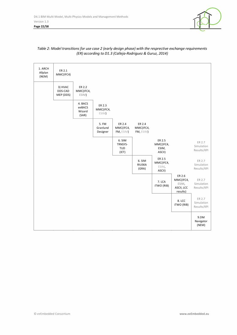
Use Case 2: Early Design
The second use case (early design phase, see Figure 7) consists of the following tasks: 2.0 Project
set up, 2.1 Check consistency, 2.2 Create construction type alternatives, 2.3 Create HVAC type
alternatives, 2.4 Create control strategy alternatives, 2.5 Enrich alternatives with O&M
information, 2.6 Simulation, 2.7 Life Cycle Assessment, 2.8 Life Cycle Cost estimation, 2.9 Decision
Making.
Figure 7: Use case 2 - early design (Geißler et al., 2014)
After the decision in the Urban Design Phase, the project set up task reviews and outputs
Decision Values to-be, Key Performance Indicators to-be as and decomposes the Key Design
Parameters to-be (e.g. shape, quality, quantity) to elements level.

D4.1 BIM Multi-Model, Multi-Physics Models and Management Methods
Version 1.3
Page 21/58
© eeEmbedded Consortium www.eeEmbedded.eu
The consistency check task takes all requirements as input and puts out the valid requirements.
In the create construction type alternatives task building shell alternatives (outer walls, windows,
baseplate and roof), layout alternatives, fit-out alternatives (inner walls, floors and ceilings) and
shading alternatives are created and stored in a BIM-based file which is then forwarded.
The create HVAC type alternatives task covers thermal zones identification and definition, loads
calculation as well as the creation of HVAC system type alternatives such as chiller + boiler +
fan coils, air-water heat pump + fan coils, splits, Variable Refrigerant Volume (VRV), etc. taking
into account the type of building, schedules, loads, etc.. It furthermore allows drafting pre-
location and pre-sizing ideas for production equipment such as boiler, terminal units such as fan
coils and distributions systems like fans and pumps, taking into account the loads calculation.
Based on the BIM input (IFC) an ESIM (HVAC) model which will be defined in T4.2 (see
eeEmbedded: Description of Work, 2013) is generated and put out.
The create control strategy alternatives task takes BIM and ESIM (HVAC) as input and puts out
ESIM (BACS). It covers the review of construction type and HVAC type alternatives as well as the
creation of BACS alternatives (sensors, controllers, actuators etc.) based on EN 15232 (DIN EN
15232).
IFC and ESIM (HVAC, BACS) are the input for the enrich alternatives with O&M information task
which includes the checking of maintainability (service lifes, schedules from FM data base), of
cleaning intensity, of accessibility and of flexibility (exchangeability of building components).The
output enriches the input with FM data.
The resulting data are used in the simulation task to create stochastic scenarios, run simulations,
to interpret results and in the end to put out simulation results.
Based on the information generated in the former tasks cost scenarios (stochastics) are prepared
in the Life Cycle Assessment task. Moreover Life Cycle Assessment (LCA) is performed on BIM-
based QTO, simulation results, service life planning and activity category results. Before they are
put out the LCA results are reviewed.
Supplied with BIM, ESIM (HVAC and BACS) and FM information the creation of stochastic
scenarios, the estimation of Life Cycle Cost and the interpretation of the LCC results (which are
the output) take place in the Life Cycle Cost estimation task.
Simulation results plus LCA and LCC results are used in the decision-making task to balance the
advantages and disadvantages of the elaborated alternatives and to prepare the design feedback
in form of Decision Values as-is which are then put out.
The resulting model transitions between the relevant components, presented in D1.5 (Zellner et
al., 2015), are illustrated in
Table 2 for the early design phase.
D4.1 BIM Multi-Model, Multi-Physics Models and Management Methods
Version 1.3
Page 22/58
© eeEmbedded Consortium www.eeEmbedded.eu
Table 2: Model transitions for use case 2 (early design phase) with the resprective exchange requirements (ER) according to D1.3 (Calleja-Rodriguez & Guruz, 2014)
1. ARCH
Allplan (NEM)
ER 2.1 MMC(IFC4)
3) HVAC DDS-CAD
MEP (DDS)
ER 2.2 MMC(IFC4,
ESIM)
4. BACS eeBACS Wizard (SAR)
ER 2.3
MMC(IFC4, ESIM)
5. FM Granlund Designer
ER 2.4 MMC(IFC4, FM, ESIM)
ER 2.4 MMC(IFC4, FM, ESIM)
6. SIM TRNSYS-
TUD (IET)
ER 2.5 MMC(IFC4,
ESIM, ASCII)
ER 2.7 Simulation
Results/KPI
6. SIM RIUSKA (GRA)
ER 2.5 MMC(IFC4,
ESIM, ASCII)
ER 2.7 Simulation Results/KPI
7. LCA
iTWO (RIB)
ER 2.6
MMC(IFC4, ESIM,
ASCII, LCC results)
ER 2.7 Simulation Results/KPI
8. LCC
iTWO (RIB)
ER 2.7 Simulation
Results/KPI
9.DM Navigator
(NEM)
D4.1 BIM Multi-Model, Multi-Physics Models and Management Methods
Version 1.3
Page 23/58
© eeEmbedded Consortium www.eeEmbedded.eu
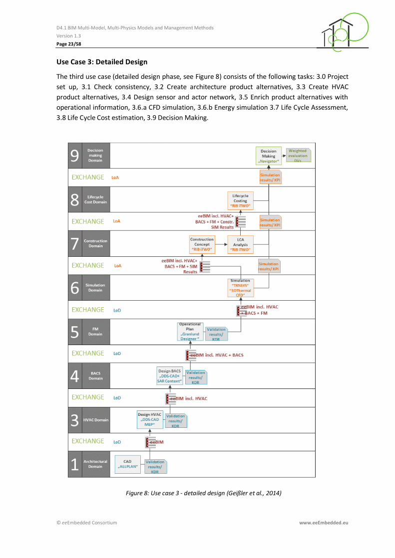
Use Case 3: Detailed Design
The third use case (detailed design phase, see Figure 8) consists of the following tasks: 3.0 Project
set up, 3.1 Check consistency, 3.2 Create architecture product alternatives, 3.3 Create HVAC
product alternatives, 3.4 Design sensor and actor network, 3.5 Enrich product alternatives with
operational information, 3.6.a CFD simulation, 3.6.b Energy simulation 3.7 Life Cycle Assessment,
3.8 Life Cycle Cost estimation, 3.9 Decision Making.
Figure 8: Use case 3 - detailed design (Geißler et al., 2014)

D4.1 BIM Multi-Model, Multi-Physics Models and Management Methods
Version 1.3
Page 24/58
© eeEmbedded Consortium www.eeEmbedded.eu
After the decision in the Early Design Phase, the project set up task reviews and outputs Decision
Values to-be, Key Performance Indicators to-be and decomposes Key Design Parameters to-be
(e.g. shape, quality, quantity) from elements level into products level.
The consistency check task takes all requirements as input and puts out the valid requirements.
In the create architecture product alternatives task the layout is detailed and material supplier
options are created and stored in a BIM-based file which is then forwarded.
The create HVAC product alternatives task covers final selection and sizing according to
manufactures products as well as the location of production equipment, terminal units and
distribution system. Furthermore it captures final sizing of the distribution system (ducts, pipes,
fans, valves, pumps, heat exchangers etc.). Based on the BIM input (IFC) an ESIM (HVAC) model
which will be defined in T4.2 is generated and put out.
The design sensor and actor network task takes BIM and ESIM (HVAC) as input and puts out ESIM
(BACS). It covers the design of the sensor and actor network (e. g. sensors, actor and controller
placement).
IFC and ESIM (HVAC, BACS) are the input for the enrich product alternatives with operational
information task which includes the checking of maintainability (service lifes, schedules from FM
data base), of cleaning intensity, of accessibility and of flexibility (exchangeability of building
components).The output enriches the input with FM data.
The resulting data are used in the CFD simulation task to create stochastic scenarios, run
simulations, to interpret results and in the end to put out CFD simulation results.
The resulting data are used in the energy simulation task to prepare and run simulations,
interpret the energy simulation results and put them out.
Based on the information generated in the former tasks cost scenarios (stochastics) are prepared
in the Life Cycle Assessment task. Moreover Life Cycle Assessment (LCA) is performed. The LCA
results are reviewed before they are finally put out.
Supplied with BIM, ESIM (HVAC and BACS) and FM information the creation of stochastic
scenarios/parameterisation, the estimation of Life Cycle Cost and the interpretation of the LCC
results (which are the output) take place in the Life Cycle Cost estimation task.
Simulation results plus LCA and LCC results are used in the decision-making task to balance the
advantages and disadvantages of the elaborated alternatives and to prepare the design feedback
in form of Decision Values as-is which are then put out.
The resulting model transitions between the relevant components, presented in D1.5 (Zellner et
al., 2015), are illustrated in Table 3 for the detailed design phase.

D4.1 BIM Multi-Model, Multi-Physics Models and Management Methods
Version 1.3
Page 25/58
© eeEmbedded Consortium www.eeEmbedded.eu
Table 3: Model transition for use case 3 (detailed design phase) with the resprective exchange requirements (ER) according to D1.3 (Calleja-Rodriguez & Guruz, 2014)
1. ARCH Allplan (NEM)
ER 3.1 MMC(IFC4)
3. HVAC DDS-CAD
MEP (DDS)
ER 3.2 MMC (IFC4,
ESIM)
4. BACS DDS-CAD
MEP (DDS)
ER 3.3 MMC (IFC4,
ESIM)
5. FM Granlund Designer
ER 3.4 MMC (IFC4, ESIM, FM)
ER 3.4 MMC (IFC4, ESIM, FM)
6. SIM
TRNSYS-TUD (IET)
ER 3.5 MMC (IFC4, ESIM, FM,
ASCII)
ER 3.7
Simulation results/KPI
6. SIM 3DThermal CFD(SOF)
ER 3.5
MMC (IFC4, ESIM, FM,
ASCII)
ER 3.7 Simulation results/KPI
7. LCA
iTWO (RIB)
ER 3.6 MMC (IFC4, ESIM, FM, ASCII, LCC
results)
ER 3.7 Simulation results/KPI
8. LCA
iTWO (RIB)
ER 3.7
Simulation results/KPI
9. DM Navigator
(NEM)
D4.1 BIM Multi-Model, Multi-Physics Models and Management Methods
Version 1.3
Page 26/58
© eeEmbedded Consortium www.eeEmbedded.eu
3.1 Architectural Models
Architectural models are virtual 3D volume models enhanced by alphanumeric data. They are
created by architects, designers or planers via Computer Aided Design (CAD) software. All
graphical elements of these models are representations of construction elements and spaces or
zones. They are classified by construction types, like walls, doors, windows, ceilings and others, to
enable controlled data handling, object recognition and object filtering. In order to obtain a
complete Architectural BIM Model, building geometry and object alphanumerical information are
required.
3.1.1 State-of-the-Art
The result of the architectural domain work is represented by a BIM Model, generated and
designed in a CAD system. There are several such systems available on the market. To better
integrate them in the planning workaround, all popular CAD manufacturers implemented
standard interfaces like IFC, to exchange their BIM data with other applications. Nonetheless, it is
important to mention at this point that the Level of Detail (LoD) and the architectural model
completeness vary from CAD system to CAD system, but depend mainly on the user inputs and
detailing work.
A smooth interdisciplinary working methodology requires (1) an interface standardization of the
BIM data structure to enable loss-free information exchange between different IT Tools, which
are used by the planers in the entire planning process, and (2) the inclusion of a minimum set
of useful information from each domain to provide sufficient input for the next working steps.
In order to fulfil the first requirement, the open standard IFC description was developed by the IAI
(International Alliance for Interoperability) as a neutral and open specification for BIM. All major
manufacturers integrated the current IFC2x3 interface into their CAD application. The new and
improved syntax IFC4 is already defined, but not broadly realized.
BIM data quality and information level provided by a CAD System do not exclusively depend on
the application capabilities itself, but also on the information which the user added into the BIM
model. The level of information added into the Architectural Model can therefore verify from
designer to designer.
3.1.2 End user requirements
End-user requirements related to the Architectural Model cover basically (1) the geometrical
model completeness including (2) the existence of alphanumerical object data, and (3) the BIM
model data quality. In addition, data readiness and standard interfaces are demanded to enable
smooth and loss-free data exchange between all domains defined in the eeE use case scenarios.
On the one hand, in the eeE project the KDPs to-be need to be checked against the real model
geometry, expressed in KDP as-is.
On the other hand, design of buildings e.g. indoor environmental comfort should be permanently
controlled via given KPIs to-be, and simulation results KPIs as-is. To support this process
appropriate simulation and analysis tools and viewers are required.

D4.1 BIM Multi-Model, Multi-Physics Models and Management Methods
Version 1.3
Page 27/58
© eeEmbedded Consortium www.eeEmbedded.eu
As experience shows, creating BIM models can be very time consuming, especially if a high LoD is
desired. A reduction of those modelling efforts is desirable but necessitates a large scale of
automatic CAD functionalities as well as adequate object libraries, which contain all required
object information.
In the early design process, most of the construction details are unknown. Construction material
selection and architectural details are usually elaborated iteratively, supported stepwise through
the energy, and cost analysis.
The eeE project improves the design process with the preparation of CAD project setups and
ensures that the CAD environment conditions are optimized according to the building
requirements. In other words, the CAD project setup will be prepared before starting the work,
enhanced by an additional templates library, to enable the architect to design the building in the
right direction. This could involve for instance the provision of certain wall, windows, façade and
other construction templates that need to be used, in order to reach the required building
performance values.
The use of templates leads to automatic detailing of CAD objects. This reduces the modelling
effort and provides all alphanumerical parameters to determine exact quantities, as well as to
execute energy and cost simulations.
3.1.3 eeE Scope and Extensions
In order to optimize and steer the design process in the right direction, several improvements are
proposed for the creation of architectural models in the following:
To enable a smooth exchange of geometry and building information between IT Tools and BIM
servers in the entire design process the standardization of CAD data interfaces is striven.
Therefore IFC2x3 or IFC4 format defined by the BuildingSmart will be supported.
The Allplan BIM CAD interoperability to third party products supported by the bim+ platform will
be improved. Nemetschek’s web based BIM platform bim+ hosts and administrates BIM models
and supports collaboration topics in the Planning, Construction and Facility Management
processes. The integration of third party tools into the bim + platform is necessary to enable best
workflow.
It is furthermore aspired to support BIM processes via BCF RESTful services. This enhancement
will enable simultaneous communication between planners and decision makers, regardless of
their location.
Another scope is the development of an “ease of use” Navigator. This mmNavigator will be a
front-end application which supports experts as well as non-experts in taking design decisions.
BIM Server extensions (EDMmodelServer and bim+ Server) will be developed to support different
scenarios in a decentralized network, for instance data upload and download services.

D4.1 BIM Multi-Model, Multi-Physics Models and Management Methods
Version 1.3
Page 28/58
© eeEmbedded Consortium www.eeEmbedded.eu
3.1.4 m2m dependencies in the eeE use cases
The transmission of the architectural models through all eeE domains is realized with the standard
IFC interface. This interface is already supported by many software companies, above all by the
most popular CAD providers.
The project communication and data transmission will be supported by the use of BCF2 (BIM
Collaboration Format, version 2).
3.2 ESIM Models
The Energy System Information Model (ESIM) covers a data structure to describe all major
systems, subsystems and components of energy systems and related data and objects including
HVAC and BACS objects. Figure 9 provides an overview of core information objects within the
ESIM.
Figure 9: Core objects within the ESIM (draft version, (Zellner & Kaiser. 2015))
3.2.1 State-of-the-Art
Currently there is no single model available which covers all aspects of energy systems in buildings
and the neighbourhood from scratch. Various existing models already cover certain aspects and
provide data structures for enhancement or adaption to cover information which are not
originally part of the model content. Certain examples for available models and standards are
listed below assigned to their domains:
Architecture/HVAC/BACS design domain o IFC2x3 model, IFC4 model (ISO 16739)
HVAC design domain o Piping and instrumentation diagram (P&ID) (ISO 10628 and ISO 14617)
BACS design domain o EN15232 o ISO 16484 o VDI 3813 o Modelica model o BACnet (ISO 16484-5), KNX (ISO/IEC 14543-3)
Thermal Building Energy and System Simulation domain o Modelica model o Energy Plus data model (IDD, IDF) o Green Building XML (gbXML)
Smart Grid domain

D4.1 BIM Multi-Model, Multi-Physics Models and Management Methods
Version 1.3
Page 29/58
© eeEmbedded Consortium www.eeEmbedded.eu
o Facility Smart Grid Information Model (FSGIM) UML o Smart Grid Architecture Model (SGAM) SysML
ESIM is going to be newly developed in T4.2. However, there are already existing data structures
covering ES and HVAC as well as BACS related information. The following provides an overview on
existing data structures or standards respectively.
IFC Model IFC2x3, IFC4
The Industry Foundation Classes, an international standard for the exchange of BIM data, are
providing a generic data schema that covers among others architectural, building service and
structural elements. Since IFC4 schema specification the data structure provides enhanced
capabilities for the modelling of building service systems. System modelling using e.g. port
connection concepts is available. Serialized IFC models are provided either in STEP physical file
format (SPF) or as ifcXML file. IFC also covers a wide range of generic HVAC type devices,
instances and attributes to match a specific product. The IFC4 schema model is improved in
several aspects, both in content and exchange: It enhances the capability of the IFC specification
in its main architectural, building service and structural elements with new geometric, parametric
and other features. It furthermore enables numerous new BIM workflows – including 4D and 5D
model exchanges, product libraries, BIM to GIS interoperability, enhanced thermal simulations
and sustainability assessments. The improvement of space boundaries and the introduction of
additional spatial zones and external spaces (against ground, water, air) as well as the
descriptiveness of shading devices can be used for energy and other performance analysis. In
addition to the EXPRESS schema, the ifcXML4 schema is fully integrated into the IFC4
specification. The additional full integration of the new mvdXML technology easily enables the
definition of data validation services for IFC4 data submissions.
Since IFC4 schema specification the data structure provides enhanced capabilities in modelling
building automation and control systems and their components.
Note that although the partners up to now committed to IFC4 it still has to be checked at the
beginning of the implementation phase if IFC4 can be used spanning across all components or if
partially fall back solutions involving IFC2x3 have to be found.
Piping and instrumentation diagram (ISO 10628 and ISO 14617)
The piping and instrumentation diagram (P&ID) is a common schematic representation in the
process industry which shows the piping of the process flow together with the installed
equipment (e.g. vessels, fans and pumps) and instrumentation (e.g. sensors and controller). The
international standards ISO 10628 - Diagrams for the chemical and petrochemical industry and
ISO 14617 - Graphical symbols for diagrams provide the appropriated symbol definitions (ISO
10628, ISO 14617).
BACnet (ISO 16484-5), KNX (ISO/IEC 14543-3)
Common ISO standards to interface building control devices used to control HVAC and Electro
installations systems. Special designed and proprietary software access these standard protocols
to program BACS devices with the intension of controlling its connected HVAC product and
systems to act as required in the physical constructed building. In theory, the HVAC domain

D4.1 BIM Multi-Model, Multi-Physics Models and Management Methods
Version 1.3
Page 30/58
© eeEmbedded Consortium www.eeEmbedded.eu
experts can set BACS generic controlling data according to ES results to optimize the HVAC
systems in the model.
EN 15232
This European Standard EN 15232 provides a structured list of control, building automation and
technical building management functions which have an impact on the energy performance of
buildings and the technical building system (EN 15232). Using BAC Efficiency Classes (A, B, C, and
D) of building automation and technical building management functions the required building
energy performance can be achieved. The EN 15232 provides a promising basis for a functional
description of building automation and control system which can be covered by BACS models.
ISO 16484
The international standard ISO 16484 provides a guideline for integrated planning and operation
of building automation and control systems. The standard defines BACS hardware, BACS functions
and a data communication protocol (BACnet) (ISO 16484).
VDI 3813
The German guideline VDI 3813 applies to room control applications in the field of building
services. The guideline is defining room automation (RA) functions which are grouped into
different function groups (sensor functions, actuator functions, operator and display functions,
application functions, management functions, and service and diagnosis functions). Each RA
function can be seen as a black box including an interface description (VDI3813).
Modelica Model
Modelica is a standardized, object-oriented, equation based language to conveniently model
complex physical systems containing, e.g., mechanical, electrical, electronic, hydraulic, thermal,
control, electric power or process-oriented subcomponents. Modelica models are behavioural
models which provide capabilities to describe major systems, subsystem and components of the
energy system (Modelica, 2015). There are a numerous open source Modelica libraries available,
containing building services system models, e.g. Modelica Buildings Library and Green Building
Library. Enhanced state chart modelling capabilities are provided since Modelica 3.3 specification,
enabling the description of simple and extensive control strategies (Modelica, 2015).
Energy Plus Data Model (IDD/IDF)
Energy Plus is a software application which provides functionalities for energy analysis and
thermal load simulation. The software takes into consideration the building geometry, user
behaviour and energy related systems. For the description of systems, a proprietary data model is
used and named as IDD/IDF format (IDD/IDF, 2015)
Green Building XML (gbXML)
The Green Building XML (gbXML) provides an open schema for exchanging BIM data. The data
structure is specialized in transferring building properties from BIM-CAD applications to
engineering analysis tools (gbXML, 2015).
Facility Smart Grid Information Model (FSGIM) UML
The FSGIM data structure facilitates an abstract representation of the energy consuming,
producing, and storage systems. It provides concept of modelling the energy characteristics of the
equipment and detailed information about systems (e.g. HVAC, lighting, security, facility

D4.1 BIM Multi-Model, Multi-Physics Models and Management Methods
Version 1.3
Page 31/58
© eeEmbedded Consortium www.eeEmbedded.eu
management systems, and industrial automation systems) inside the facility. The FSGIM is
specified using Unified Modeling Language (UML) (FSGIM, 2015).
Smart Grid Architecture Model (SGAM) SysML
The Smart Grid Architecture Model developed by Siemens AG (Siemens, 2012) targets the
modelling of a smart grid architecture of intelligent electrical power grid covering technical,
functional, communication-related and informational aspects. The model contains data structures
of all major sub-domains of (electrical) energy systems (including generation, transmission,
distribution and facilities) relevant for the hand-over to end-users, see Figure 10. Because of the
focus on the electrical energy domain this model has to be extended to cover thermodynamic
facilities like heating and cooling systems. The SGAM is formulated with the help of SysML (SGAM,
2015).
Figure 10: Schema introducing the SGAM (SGAM, 2015)
3.2.2 End user requirements
In general an energy system related data model is intended to support the design team within the
design process elaborating, shaping and fine-tuning appropriate concepts for energy systems
related to the building and the building site taking into account the boundary conditions provided
by the neighbourhood.
The conceptual design of the energy system is one of the main tasks within the Urban Design
phase. Within the Early Design phase the energy systems will get more detailed and adapted on
the progress of the architectural design of the building.

D4.1 BIM Multi-Model, Multi-Physics Models and Management Methods
Version 1.3
Page 32/58
© eeEmbedded Consortium www.eeEmbedded.eu
In usual cases the energy system of a building or a neighbourhood is formed by a set of different
systems, subsystems and components. Reflecting the modularized concept of the system
engineering approach energy systems are formed by several main subsystems.
Figure 11 shows major subsystems of the energy systems containing (1) heat generation devices,
(2) heat storage, (3) heat distribution system covering heat circuits, (4) a controller device but also
the (5) consumption block.
The mentioned objects can be aggregated by function into several modules or blocks. Within a
system engineering approach typical systems configurations and setups are identifiable as a pre-
step for generalized and formalized abstraction. The outcomes of this analysis are transferred into
templates which could cover almost complete energy systems, subsystems or single components
as pre-defined modules for typical design cases. The eeE templates covering energy system data
will be structured in compliance with the introduction given in the chapters of this document.
Figure 11: Simplified example schema of energy system. Please note that not all required components and information flows of the ESIM are indicated (Zellner & Kaiser. 2015).
3.2.3 eeE Scope and Extensions
ESIM is a newly developed data structure that covers information related to the energy system (as
mentioned above: major system, subsystem and components of the energy system). Due to
strong interdependencies between energy system (building internal or external), HVAC system as
well as automation and control system, it is aimed that ESIM covers and includes BACS and HVAC
data structures as well.
Furthermore it is intended to follow a Multi-Model approach. Hence, the ESIM data structure will
include existing data structures as mentioned above and newly specified data structures. The new
specified data structures will close the gap of existing standards and will ensure an integrated
information space.

D4.1 BIM Multi-Model, Multi-Physics Models and Management Methods
Version 1.3
Page 33/58
© eeEmbedded Consortium www.eeEmbedded.eu
The scope of ESIM will be explained in detail within D4.2. More detailed information about
templates used regarding to energy systems is provided within D2.3 (Guruz et al., 2015b).
3.2.4 m2m dependencies in the eeE use cases
As mentioned above ESIM benefits from the Multi-Model approach within eeE. Currently ESIM
should be based on UML or SysML data structures stored within an XML-based file format,
potentially the XML Metadata Interchange (XMI) format.
There is no specific software application named ‘Energy System Designer’ (ESD) as editor for
energy systems within the DOW. Because of the early development status of ESIM and the affinity
of the current approach to UML/SysML existing editors could be used. NEM evinced interest for a
further implementation depending on the expected functionality of the editor. Due to that early
stage of development the m2m dependencies could be expressed as follows – in spite of further
specification later on in the project run: (1) The BIM-CAD Application ALLPLAN provided by
Nemetschek – which possibly contains a software module, providing functions similar to Energy
System Designer (ESD) – delivers information in the IFC format and potentially the data format of
the ESIM model (e.g. SysML) covering all design phases. (2) The Energy System Designer (ESD) –
possibly a SysML editor – generates the ESIM related data following the SysML data standard
covering all design phases with focus on the urban design phase. (3) The HVAC engineering
software application DDS CAD delivers especially HVAC related data, using the IFC standard and
the ESIM data structure, covering the early and detailed design phase. (4) The BACS design
software application Sauter eeBACS Wizard developed by Sauter AG delivers especially BACS
related data, using the IFC standard and the ESIM data structure within the early and detailed
design phase. (5) Downstream of the authoring tools ALLPLAN, DDS-CAD, ESD and Sauter eeBACS
Wizard the analysis tools (energy simulation SIM, life cycle cost analysis LCC and life cycle
assessment LCA) have to extract all the data out of IFC und ESIM data models covering
information of all design domains.

D4.1 BIM Multi-Model, Multi-Physics Models and Management Methods
Version 1.3
Page 34/58
© eeEmbedded Consortium www.eeEmbedded.eu
3.3 HVAC Models
3.3.1 State-of-the-Art
HVAC devices and systems are designed and maintained by DDS-CAD BIM native model. At
present time software vendors provide functionality in native models to build a sustainable
model, from early phase generic product into detailed specific product and system design. The
HVAC designer interacts with other actors in different domains in the project and strongly
depends on a trustworthy flow of information. Data exchange processes between model domains
still depend on human knowledge although various Open BIM exchange models exist for different
purposes to assist the interaction between the model domains. Open BIM is a universal approach
to the collaborative design, realization and operation of buildings based on open standards and
workflows. Open BIM is an initiative of buildingSMART and several leading software vendors using
the open buildingSMART data model. In the following, the before mentioned exchange models
are listed:
Architecture/HVAC design domain o IFC2x3 model, IFC4 model (ISO 16739)
BACS/HVAC design domain o IFC2x3 model, IFC4 model (ISO 16739) o BACnet(ISO 16484-5), KNX (ISO/IEC 14543-3)
Building Energy and System Simulation domain o Green Building XML (gbXML) o IFC2x3 model, IFC4 model (ISO 16739)
The data structures and standards which already cover some HVAC aspects are introduced in
subchapter 3.2.1.
3.3.2 End user requirements
The vision is to enable the user to build a BIM HVAC system «As built» completely energy
optimized with integrated Building Automation and Control System (BACS). The eeEmbedded
target is to improve interoperability between actors in the different modelling phases of Building
Services domains with focus on energy analysis, using Open BIM. IFC4 supports the required HVAC
data needed to build a sustainable HVAC model in a building environment. State of the art is
mainly user driven and process and knowledge exchange oriented, instead of software assisted
data exchange. HVAC end users expect related model domains to exchange data and keep models
sustainable throughout all phases to meet the spaces climate and energy requirements.
Improved interoperability between actors is needed in the different modelling phases of Building
Services domains with focus on energy analysis, IFC4 usage and MVD (Model View Definition)
improvement as well as access to common templates, open libraries, products and materials. (i.e.
IFC Libraries and extensions)
3.3.3 eeE Scope and Extension
Stronger interoperability between domains is mandatory to achieve a sustainable HVAC model
during the BIM planning phases. Actors and domains are required to be familiar with the process

D4.1 BIM Multi-Model, Multi-Physics Models and Management Methods
Version 1.3
Page 35/58
© eeEmbedded Consortium www.eeEmbedded.eu
and the date exchange format. BuildingSMART covers the format with IFC schema (as model),
various exchange views with MVD and the need for a common BIM communication platform with
BCF. The Scope and extension regarding the HVAC domain context of eeE is to improve HVAC
design and provide energy efficient buildings using Open BIM (IFC4) in the planning process.
3.3.4 m2m dependencies in the eeE use cases
Energy optimized HVAC solutions are designed in the HVAC domain. During the BACS design, the
model is enriched with BACS information adapted to the HVAC design. During a later LoD phase,
the HVAC model is checked and adapted to the chosen BACS solution. In the detailed design
phase, the chosen BACS and HVAC solutions are together placed for an optimal behaviour.
Architecture/HVAC design domain
One of the main and early phase factors in HVAC model build up is to establish the building spaces
need for ventilation, heating and cooling. What system is to be used, what sizing is needed to
provide required air exchange and space temperature. A building energy analyses is needed to be
done to provide a complete picture that covers all neighbourhood-spaces, including building
surface against air and soil, location, angle, shadows, space type, usage, occupancy rate, seasons,
etc. User comfort also covers noise reduction and the HVAC system’s ability to exchange air in
spaces. Analyses will often include sound, pressure, flow rate calculations and second level space
boundary to calculate heating and cooling load.
BACS/HVAC design domain
Energy optimization is an important part of the more detailed HVAC model build-up, selecting
HVAC products that in turn cover control strategies for energy management tuned by the
integrated BACS. Common accessible open product libraries and common templates to meet the
project and process requirement are preferred (i.e. IFC Libraries and extensions).

D4.1 BIM Multi-Model, Multi-Physics Models and Management Methods
Version 1.3
Page 36/58
© eeEmbedded Consortium www.eeEmbedded.eu
3.4 BACS Models
The BACS Model covers a data structure to describe all major systems, subsystems and
components of the building automation and control system. The BACS model comprises
information of all products and engineering services for automatic controls, monitoring and
optimization, for operation, human intervention and management to achieve energy-efficient,
economical and safe operation of building services.
The BACS model domain covers the whole automation pyramid in Figure 12. In detail, the BACS
model can be divided in Management Level (supervision of the building automation with a global
building controller), Automation Level (plant automation e.g. air handling unit according to
EN15232 with its main control functionality and interactions) and Field Level (Sensors and
actuators with its specific control).
Figure 12: Automation Pyramid Layer
The mentioned examples above refer to the automation pyramid for a building. However, the
automation pyramid also holds for districts. On district level the BACS model covers control
strategies for energy management, e.g. control of energy demand and energy supply. Figure 13
illustrates the relation between building level and district level of the BACS model. The BACS
model on district level can be seen as DACS model. However, it is part of the ESIM model domain
too.
Figure 13: Relation among DACS and BACS based on an illustration from (Solvik et al., 2014)
D4.1 BIM Multi-Model, Multi-Physics Models and Management Methods
Version 1.3
Page 37/58
© eeEmbedded Consortium www.eeEmbedded.eu
3.4.1 State-of-the-Art
Currently there is no single model or standard available which covers all aspects of building
automation and control systems. Various models still exist which cover certain aspects and
provide data structures to enhance or adapt the models to cover information which are not
originally part of the model content. Certain examples for available models/standards are listed
below:
Architecture/Building Services design domain o IFC4 model SPF
HVAC design domain o Piping and instrumentation diagram (P&ID) (ISO 10628 and ISO 14617)
BACS design domain o EN 15232 o ISO 16484 o VDI 3813/3814 o Modelica model o KNX o BACnet
The BACS model in combination with the ESIM model is going to be newly developed in WP4.
However, there are already existing data structures covering some aspects of building automation
and control system related information. Those data structures and standards were introduced in
subchapter 3.2.1.
3.4.2 End user requirements
In general a building automation system related data model is intended to support the design
team within the design process elaborating, shaping and fine-tuning of appropriate control
strategies for operating the district energy system and technical building systems in an energy
efficient way while taking into account the building users comfort conditions.
The elaboration of basic control strategies for conceptual design of the district energy system is
one of the main tasks within the Urban Design phase. Within the Early Design phase the control
strategies related to the technical building systems and the user comfort will get more detailed
and adapted on the progress of the architectural and HVAC design of the building. In the Detailed
Design phase the functional control strategies are mapped to manufacture dependent BACS
equipment and the optimized placement of the sensors and network is elaborated.
From end-user point of view the BACS model covers information to facilitate (1) design of multiple
automation and control system configurations managing energy demand and supply while
maintaining user comfort, (2) specification of BACS function that generates multiple alternatives
and solutions based on EN 15232 that can be used later on in simulations, and (3) import of
products characteristics from data base and catalogues for BACS components (actuators, sensors
and controller).
3.4.3 eeE Scope and Extensions
In general the scope of the BACS model is to provide a data structure that allows to describe
software, hardware and service aspects according to the BACS definition illustrated in Figure 14.

D4.1 BIM Multi-Model, Multi-Physics Models and Management Methods
Version 1.3
Page 38/58
© eeEmbedded Consortium www.eeEmbedded.eu
BACS models are aimed to provide structural, functional and physical information of the building
automation and control system.
Figure 14: BACS model - eeE Scope (based on Frost & Sullivan, 2010)
The integration in the eeeBIM data model domain and especially the integration in the ESIM
information space form the main scope of the BACS model in eeE. Therefore the elaboration of an
appropriated BACS model concept and the integration in the ESIM and eeeBIM data model
domain is aimed. For this purpose, existing data structures and standards, mentioned above, will
be taken into consideration and potential information gaps will be defined. To overcome these
gaps the BACS model information space will be extended.
The following aspects have to be covered by the BACS data structure:
System and component description
Interface description (physical and functional interface)
Identifier description (physical and virtual data points)
Functional description (BACS and RA functions)
Manufacturer information
LCC/LCA information
A further aspect regarding the BACS model forms the generic BACS template concept. The
integration of BACS knowledge templates into the BACS data model domain has to be in line with
the aimed BACS concept.
3.4.4 m2m dependencies in the eeE use cases
There are strong dependencies to ESIM models and HVAC models from BACS model point of view.
ESIM (see section 3.2) covers a data structure to describe all major systems, subsystems and
components of energy systems and related data and objects including HVAC and BACS objects. In

D4.1 BIM Multi-Model, Multi-Physics Models and Management Methods
Version 1.3
Page 39/58
© eeEmbedded Consortium www.eeEmbedded.eu
addition there are strong m2m dependencies among IFC4 models and BACS models as well. The
IFC4 model provides the physical representation (object geometry) and placement of the BACS
equipment inside the building.
Due to the early stage of development the m2m dependencies could be expressed as follows – in
spite of further specification later on in the project run.
In the Early Design conceptual BACS solutions are designed and elaborated by means of the
Sauter eeBACS Wizard. The Sauter eeBACS Wizard uses Architectural model (IFC4) and HVAC
model (IFC4), which provide results of the previous design steps carried out in the Architectural
and HVAC domain. The different BACS solutions are provided later on in an ESIM data structure,
which comprises the BACS model. In these early design steps the different control strategies,
described in BACS model, are interlinked to spatial structure elements (e.g. in case of room
automation) or to HVAC system types (e.g. in case of plant automation) contained in the IFC
model. Both, IFC model and BACS model form the basis for simulation and analysis tasks in Early
Design phase.
In the Detailed Design phase the physical representation of BACS equipment, fulfilling a specific
functionality, is added and the corresponding placement is done in the Architectural model (IFC4).
Further detailed control strategies for single HVAC components are elaborated. In general the
BACS model is used to carry a more detailed description of the BACS equipment, these include: (1)
BACS functional description, including interface and identifier specifications, (2) energetic
properties and behaviour, and (3) an integrated system view. In summery there exist strong
dependencies to Architectural and HVAC model (both IFC4) and ESIM model, whereas the latter
includes the BACS model data structure.

D4.1 BIM Multi-Model, Multi-Physics Models and Management Methods
Version 1.3
Page 40/58
© eeEmbedded Consortium www.eeEmbedded.eu
3.5 FM Models
The Facility Management (FM) model on the whole supports all core parts of facility
management: communication, emergency preparedness and business continuity, environmental
stewardship and sustainability, finance and business, human factors, leadership and strategy,
operations and maintenance, project management, quality, real estate and property management
as well as technology.
One scope of eeE is to bring FM competence and information to support the analysis of FM
already during design. So it does not include the parts, which only support management of the
facility, when it is already built and taken into use. As a consequence FM models, which mainly
support the information hand-over to FM, such as COBie, are not included in the scope of eeE FM
models. On the other hand, a part of the information which supports operation and maintenance
of the building also allows analysis of FM during design.
3.5.1 State-of-the-Art
Model based FM applications are already available for space management, maintenance manual,
monitoring of energy consumption and environmental impacts, maintenance budgeting, long-
term planning, etc. Maintenance manual applications, utilizing models either on a restricted basis
or more widely, are available for management of technical data, service requests, contracts,
documents, various maintenance tasks and maintenance history.
The majority of current FM systems utilizes legacy data models. If building data is included, it is
typically included as vectorized drawings together with attributed data. Only few use open
standards like IFC.
Model-based analysis of FM during design is neither theoretically planned nor practically
implemented. Granlund Designer currently manages central HVAC equipment data and has
proprietary import/export links to chart level models of the HVAC system. Currently Granlund
Designer supports only design and contracting of HVAC and electrical systems and has no links to
FM information.
The FM modules for EDMmodelServer provide real integration with BIM models in IFC2x3, and
also utilize IFC2x3 for data storage of FM data, with some minor extensions.
3.5.2 End user requirements
FM module in Granlund Designer is used to link HVAC components to FM templates (service life,
maintenance need). Within the eeE scope and referring to eeE use cases, the end user
requirements sums up to: “As a user I want to enrich the data model with necessary FM data so I
can calculate maintenance costs.”
The input data required are taken from BIM. Within the eeE use cases only HVAC BIM for FM is
relevant. Each HVAC equipment object is linked to FM template based on the equipment type
definition. The attributes in the FM templates for each object type are amongst others the
expected life time and the service need (service program, spare parts).
The enriched data model is exported to be utilized by LCC to calculate FM cost as part of the life
cycle cost and by LCA to calculate environmental impact of the replaced HVAC components.

D4.1 BIM Multi-Model, Multi-Physics Models and Management Methods
Version 1.3
Page 41/58
© eeEmbedded Consortium www.eeEmbedded.eu
3.5.3 eeE Scope and Extensions
The FM model is developed based on data structures that cover FM related information and is
linked to the HVAC model. The needed eeE extensions must ensure interoperability between
HVAC design and facilities management. This means identification and agreement on the
information and actual data sets needed for FM data exchange, and formulation of this
agreement as “FM exchange requirements”. This includes identification of IFC constructs needed:
zones, areas, volumes, spaces etc. To achieve necessary information exchange compatibility, the
IFC4 standard has to be supported. Finally, the FM data handling requires to link HVAC
components to FM templates, and to provide mapping of the FM templates to the actual data
sets defined for the exchange.
3.5.4 m2m dependencies in the eeE use cases
The FM tool will have the following dependencies: The Granlund Designer will receive its input
data in IFC4 format, primarily HVAC from DDS CAD. The extent of data will be defined as ERs
and/or MVDs as appropriate. FM data provided by Granlund Designer will be consumed by
LCC/LCA analysis tools. Information here will also be carried by IFC4 format, when applicable, and
defined as ERs and/or MVDs as appropriate.

D4.1 BIM Multi-Model, Multi-Physics Models and Management Methods
Version 1.3
Page 42/58
© eeEmbedded Consortium www.eeEmbedded.eu
3.6 Climate Models
Energy analysis needs weather (atmospheric conditions over a short period of time) and climate
data (atmospheric behaviour over relative long period of time).
Climate data are used for building energy simulations, energy demand estimation, building and ES
design evaluations of different scenarios, long term building and system energy performance.
The need for appropriate climatic data for long term prediction of the annual energy performance
of buildings (e.g. thermal comfort conditions, heating and cooling loads) has led to the
development of the so called Test Reference Years (TRYs) a term mainly used in Europe or Typical
Meteorological Years (TMYs) a term mainly used in the USA.
Building simulation software requires comprehensive TRYs which are commonly composed of
hourly values for a one year period (12 typical meteorological months) rather than extreme
conditions of actual (measured) weather data. TRY data represent a year of typical climatic
conditions for a location, preserving the main local weather characteristics, for example, typical
cold or hot conditions, but consistent with the local long term averages. However, TRYs should
not be used to predict weather for a particular period of time.
A comprehensive overview of various weather data sets and methodologies is available in
(Crawley, 1998) and (Forejt et al., 2006).
For building energy analysis based on transient simulations the consideration of well-chosen
weather/climate data sets is essential to generate results which intend to be close to the real
world behaviour of the building and the existing energy systems. Due to the ability of the used
simulation models and the addressed LoD the following climate elements have to be part of the
weather/climate data set:
Global solar radiation on a horizontal surface
Diffuse solar radiation on a horizontal surface
Air temperature
Air humidity
Wind speed
Wind direction
Precipitation
3.6.1 State-of-the-Art
A weather profile is a continuous time series with a fixed hourly time step. Several standard
formats exist to catalogue weather data that have emerged over the years. Such weather profiles
can be obtained for many European locations. The most common weather data formats used for
energy calculation and simulation are:
Test Reference Year (TRY)
Typical Meteorological Year (TMY2)
Weather Year for Energy Calculation (WYEC2)
International Weather for Energy Calculations (IWEC)
Actual historic weather data (AHW)
Non reference years (NRY)

D4.1 BIM Multi-Model, Multi-Physics Models and Management Methods
Version 1.3
Page 43/58
© eeEmbedded Consortium www.eeEmbedded.eu
Some simulation software vendors recommend using TMY2 or WYEC2 weather profiles. However,
not all energy calculation and simulation software depend on the standard formats for weather
data, but rather use their own proprietary formats. Such weather profiles can be constructed
from available historic weather data or by filtering and transforming standard profiles, provided
they contain all the necessary data.
The Test Reference Year format TRY provided by the German Weather Service ‘Deutscher
Wetterdienst DWD’ covers 15 locations/climate regions within Germany. The last update was
delivered in 2011. The data sets are available on hourly basis and contain three different data
sets: (1) normal average year, (2) hot year and (3) cold year.
The Typical Meteorological Year Format version 3 called TMY3 provided by the ‘National
Renewable Energy Laboratory (NREL)’ of the United States is available on hourly basis and the
current version was updated in 2015. The data sets are available for 1.020 locations within USA
and representing typical weather conditions.
The International Weather for Energy Calculations format IWEC provided by ASHRAE includes
data sets for 3.012 locations outside USA and Canada on hourly basis extracted out of the
Integrated Surface Hourly (ISH) data base maintained by the National Climatic Data Center (NCDC)
of the USA. This data sets cover weather information of up to 25 years.
The data are delivered on hourly basis for minimum one year. Certain commercial providers
deliver data sets on sub-hourly basis. For example “Metronome” application provides reliable
estimation of hourly weather data (e.g. solar radiation, temperature and other meteorological
parameters), based on over 8300 weather stations worldwide.
For long term analysis the climate change will be considered with the help of a drift factor used in
conjunction with the climate elements when analysing upcoming periods.

D4.1 BIM Multi-Model, Multi-Physics Models and Management Methods
Version 1.3
Page 44/58
© eeEmbedded Consortium www.eeEmbedded.eu
3.7 Simulation Models
The simulation model for the whole building energy performance evaluation and assessment,
through all building design phases, involves many individual simulation models for each
simulation tool used. Building performance and behaviour aspects, like thermal efficiency
assessment and HVAC performance optimization, CFD analysis and thermal comfort criteria
fulfilment and interior lighting and acoustics simulation require a multitude of domain specific
models all linked to the BIM as a base of the whole building design. Heterogeneous multi-level
models are utilized across different engineering disciplines. In addition to the support of different
levels of detail users have also need to combine optimization computation and model uncertainty
assessment into their simulation experiments.
Following the definition of transient thermal simulation approaches according to VDI6020:2001
Blatt 1 (VDI 6020, 2001) two main classes of simulation models are identifiable: (1) thermal and
energy simulation of buildings (TEB), and (2) thermal and energy simulation of systems (TES).
Thermal building energy simulations (TEB), mentioned first, cover an analysis of the thermal
reaction of the building and/or certain spaces on transient inputs, especially taking into account
the outdoor climate, the user behaviour and the related set points for indoor temperature.
Depending on the used simulation models, the LoD modelling of the building itself and the
transient influences, this kind of analysis delivers results regarding spaces or parts of spaces and
the thermal behaviour of the building construction elements.
The second approach called ‘Thermal Energy System Simulation (TES)’ is based on or includes TEB
but also includes the behavioural models of HVAC and BACS systems and components. Both kinds
of analysis are working with simulation steps of maximum one hour or explicit lower time steps till
to seconds, depending on the question which has to be answered. They are strongly influenced by
the LoD of the used simulation models. In addition to the thermal behaviour of building and
spaces, detailed results describing the operation of the HVAC components and the energy system
are delivered.
CFD simulations are carried out for TEB and TES simulation coupled with Energy Simulations in
order to obtain the detailed indoor climate, e.g. for the optimal design of the building envelope,
the prediction of thermal comfort conditions, the evaluation of the HVAC performance, the
optimization of HVAC systems (size of diffusers and location in the zone) and the design of natural
ventilation.
3.7.1 State-of-the-Art
Various Building Energy Modeling (BEM) tools and interfaces have been developed for the energy
simulations of the whole building embedded in its environment and taking into account transient
conditions. Most of them are based on the ESP-r, Energy Plus, DOE-2, BLAST and TRNSYS
simulation engines that use a multi-zone approach considering one calculation node per zone for
air temperature determination. The most advanced tools include models for moisture conditions
of the indoor air, models for solar radiation gains, photovoltaic systems and renewable energy
sources use. Several alternative architectural designs are evaluated according to building energy
consumption cost dimension and results are incorporated to the lifecycle cost model to reach an
optimum trade-off between energy and cost resulting in an optimum design.

D4.1 BIM Multi-Model, Multi-Physics Models and Management Methods
Version 1.3
Page 45/58
© eeEmbedded Consortium www.eeEmbedded.eu
The BEM tools are used for: (1) thermal load simulation, for determining sizing of equipment such
as fans, chillers, boilers, etc. and (2) for energy analysis to determine thermal comfort conditions
and evaluating the energy cost of the building over longer periods of time (for an already
calculated HVAC system) and providing data for detailed analysis of some particular spaces via
CFD simulations.
Despite the existence of an increasing number of BIM models that are linked to energy
performance simulation models and the existence of models that are linked to BIM authoring
tools (CAD) within proprietary environments, there are still limitations to the current BIM tools for
energy analysis in terms of interoperability and quality of the results [Bazjanac, 2011]. The IFC
HVAC schema is currently widely used for HVAC information exchange between building ES tools.
Additional data exchange between ES tools usually requires proprietary data formats.
Typical ES data models are stand-alone, usually in the form of plain text files with poor or non-
existent interfaces for data exchange. In fact, there is no official standard for the simulation
domain. Existing simulation tools (E+, DOE-2, IES, etc.) fail to take advantage of standard data
exchange tools that are available for data in the XML or IFC format. More recent exchange
models, such as gbXML, enable the exchange of concepts previously defined in BDL and IDD using
XML (gbXML, 2010).
For CAD/BIM and ES interoperability the IFC model needs to be extensively pre-processed and
appropriate energy specific model views have to be derived that need to be enriched with
incomplete or missing domain specific information (e.g. thermal properties, occupancy and
operational schedules) to comply with the building model used by the Building Energy
Performance Simulation tools (BEPS) (Gudnason et al., 2015). Data enrichment platforms have
been previously demonstrated, for example in COBie (East et al., 2012) – an intermediary model
for “as built/operated” information in downstream FM exchange, by Simergy (See et al., 2011)
together with SimModel (O’Donnell et al., 2011) – a BIM based integration platform for whole
building energy performance simulation. The more generic Multi-Model framework for energy
enhanced BIM (Liebich et al., 2011) was developed in the EU project HESMOS and the platform
ontology, eeBIMOnto (Kadolsky et. al., 2014), in the EU project ISES.
3.7.2 End user requirements
End-users and especially non energy experts (like architects) require the seamless integration of
ES tools of escalating LoD and a decision making support in accordance to KPIs or user defined
energy performance criteria concerning the operation lifecycle of buildings.
Therefore a system, which organizes the data flow in a unified model, enabling effective exchange
of data is required. The final goal is to simplify and automate the information exchange processes
among different tools, and develop enabling technologies and platforms to facilitate and establish
an integrated system around a BIM-centred simulation matrix with multiple tools and users.
With all the above considerations and limitations in mind, the simulation domain requires an
interoperable data model that facilitates:
Data exchange between existing simulation tools
Bi-directional exchange of data within eeeBIM thus enabling seamless workflow

D4.1 BIM Multi-Model, Multi-Physics Models and Management Methods
Version 1.3
Page 46/58
© eeEmbedded Consortium www.eeEmbedded.eu
Use of templates as another key feature that empowers users and allows them to leverage pre-configured data sets and configurations, thus expediting simulation model development.
Easy generation of design alternatives for optimization purposes.
3.7.3 eeE Scope and Extensions
A consistent data model (ESIM) across all aspects of the building simulation process and the
building lifecycle is required, thus preventing information loss. The model accounts for new
simulation tool architectures, existing and future systems, components and features. In addition,
it should be a multi-representation model that enables integrated geometric and MEP simulation
configuration data.
The eeEmbedded simulation data model intends to incorporate a number of features to address
current domain weaknesses (as highlighted in the State Of the Art subsection), a set of
requirements for a shared simulations model and is easily extensible to account for future domain
advances. It ensures interoperable exchange of simulation data within the simulation domain and
most importantly across an entire building project. The unique design enables interoperable data
exchange and uses a number of features to do so. These are:
Mappings to/from existing domain models
Property set definitions (for using an extended set of data types.)
Object type definitions
Model topology for energy systems
Templates with, where possible, reference to lower level data contained in libraries Representation of context and outputs upon user’s request
Analysis tools have to be integrated to the eeeBIM system and have to be linked with the data
provided by Architectural, ESIM (energy system), BACS and HVAC and FM data structures. They
also should provide suitable representation of output results to support decision making for
optimized building solutions.
3.7.4 m2m dependencies in the eeE use cases
Energy performance and thermal comfort simulation tools (TRNSYS for ES and CFD for urban
design and thermal comfort performance) require (1) building elements, 2nd level space
boundaries, products and materials (via IFC4 and/or XML files), (2) weather data (TRY or WDV), (3)
occupancy data and heating/cooling set point temperature(gbXML), (4) HVAC equipment data
produced with DDS-CAD MEP design tool (IFC2X3, IFC4, gbXML), (5) BACS equipment (IFC4), (6)
Type of analysis and Decision making parameters (job matrix, see chapter 3.5. Simulation
Management Services of D1.5) and (7) design alternatives.
CFD and ES tools use different space discretization and time scale. ES provides CFD analysis with
all the required boundary conditions for the detailed simulation of a subsystem of the building (or
even the whole building). ES results are mapped on IFC objects and are consequently translated to
boundary conditions on the space boundaries of the building or thermal envelope surrounding
the flow domain. HVAC systems (via ESIM model) are also included into the CFD model. CFD
simulation requires location, geometry and flow rate (m3/h) of the HVAC air suppliers, as well as
the air properties (in the psychrometric diagram) needed for the efficient

D4.1 BIM Multi-Model, Multi-Physics Models and Management Methods
Version 1.3
Page 47/58
© eeEmbedded Consortium www.eeEmbedded.eu
ventilation/cooling/heating of the space. These data are provided by the HVAC manufacturers and
could stand as templates in the ESIM data model.
CFD simulations could provide more accurate U-values to ES tools for material assemblies of the
building.
Usually CFD detailed simulations are carried out for specific cases selected among design
alternatives obtained by ES on a yearly basis (i.e. worst case scenario or design that could not be
covered by ES, such as displacement or natural ventilation). The alternative approach is to couple
ES and CFD applications directly and exchange the convective heat transfer information between
the two programs.
All the data generated during CFD analysis are linked back to IFC Models. Mesh and CFD results do
not currently exist and will need to be developed as entities of the ESIM data model.

D4.1 BIM Multi-Model, Multi-Physics Models and Management Methods
Version 1.3
Page 48/58
© eeEmbedded Consortium www.eeEmbedded.eu
3.8 LCC Models
The life cycle cost model is based on design-to-cost methodology considering the complex states
of different cost spread over the entire life of the system. The Cost-Code Catalogue is
fundamental and classifies different cost components and their relationships. The Cost Codes
Catalogue has a dual purpose. It forms the Cost Breakdown Structure (CBS) for the estimate.
Additionally, any branch of it can be used directly in the estimate or an assembly to hold a cost,
either with a fixed unit rate or with a floating unit rate. A hierarchical cost profile is used at each
level subsequently with the cost break down structure framework.
3.8.1 State-of-the-Art
The LCC model is supported by using iTWO modules, such as element planning, BoQ, cost
estimation, cost catalogues, object model, activity model, and scheduling to finally obtain the
desired output. The LCC model is structured using the data provided by architectural design, ES,
HVACS and by BACS. The file formats currently supported are CPI, IFC (IFC2x3, IFC4), DWG and
XML.
3.8.2 End user requirements
In order to obtain the desired Life Cycle Cost output, the user has to be enabled to match and link
the parametric design to the LCC templates. Furthermore the model has to provide the
opportunity to create miscellaneous cost catalogues, including all costs, which arise in the whole
life cycle of a building. This cost catalogue consists of information such as labour, equipment,
maintenance, operational planning, etc. The user also should have the possibility to import actual
costs from XML- or CSV files. Moreover the user needs to be able to generate remaining costs
from existing data. These costs need to be integrated with projected costs in the LCC cost
breakdown structure to provide a time-dependent analysis of a projects whole life cycle cost
process. These multiple processes have to be performed in parallel. Furthermore, the LCC model
has to support project phasing in the different use cases. Controlling functions and structures
have to be created, which provide flexible methods for the clients to manage and understand the
project. And users should be able to assign activities or BoQ elements to controlling units.
3.8.3 eeE Scope and Extensions
The LCC model will be developed based on data structure that covers information related to the
total cost involved in the life cycle of a building. To estimate the entire life cycle of a building, this
model must be linked with the data provided by the Architectural, ESIM, BACS and HVAC, FM data
structures.
Thus, it is the scope with the perspective of cost analysis to evaluate the exploratory part of data
from energy, HVAC, BACS and FM stimulation. Hence, results from these model domains on each
use case will enable decision-making from cost realization perspective. The LCC tool will enhance
decision-making and financial planning by facilitating decision makers to select the most
economical infrastructure

D4.1 BIM Multi-Model, Multi-Physics Models and Management Methods
Version 1.3
Page 49/58
© eeEmbedded Consortium www.eeEmbedded.eu
3.8.4 m2m dependencies in the eeE use cases
Currently the LCC model is described as XML-based file format stored in an SQL database. The
m2m dependencies in eeE use cases can be defined as follows: The data model of Allplan as
IFC4 file is required for the calculation of all costs which arise in the entire life cycle of a building.
Any other information that are essential to evaluate the LCC must be provided as schematized
XML file in order to evaluate the results of each corresponding domain. This includes, for instance,
all evaluations of the HVAC, BACS and FM domain. The resulting outcomes are forwarded to the
decision-making domain as XML-based files.

D4.1 BIM Multi-Model, Multi-Physics Models and Management Methods
Version 1.3
Page 50/58
© eeEmbedded Consortium www.eeEmbedded.eu
3.9 LCA Models
The life cycle assessment model is based on design-to-environmental methodology considering
the different material and potential impacts associated over the entire life of the building. The
commodity catalogue is used to store material estimation codes. The advantage of using
commodities as material in LCA models is to set wastage factors, link commodities to ERP
database, carry out material quotation, comparisons and specifies material details like densities to
calculate the potential environmental impact. Commodities are arranged hierarchically. LCC and
LCA analysis in an early design phase are used to perform a risk assessment. Thus, evaluating
economic and environmental design decisions allows developing more sustainable urban areas.
3.9.1 State-of-the-Art
The LCA model is supported by using iTWO modules such as element planning, BoQ, material
estimation, commodity catalogue, and currency catalogue concerned with the assignments
management of the LCC model. The LCA model is structured using the data provided from
architectural design, energy system, HVAC system, building automation and control system. The
file formats currently supported are CPI, IFC (IFC2x3, IFC4), DWG and XML.
3.9.2 End user requirements
In order to obtain the desired Life Cycle assessment, the user has to be enabled to match and link
the parametric design to the LCA templates. Furthermore the model has to provide the
opportunity to create new commodity groups, subgroup including all material specifications,
which can arise in the whole life cycle of a building. Commodities are referenced to cost codes to
estimate the required cost associated with the project to carry out LCC. Thus, LCA estimates the
environmental factor associated with the building and further linked to estimate the cost due to
these impacts on the project. This cost catalogue consists of information such as material
specification, density, unit of measurement, etc. The user has to get the possibility to import
commodity libraries from excel or import and export in XML files. The commodities can be
mapped to a resource so that the estimated detail can be passed to schedule. Moreover, the LCA
model needs to support project phasing in the Early Design and in the Detailed Design use cases.
3.9.3 eeE Scope and Extensions
The LCA model will be developed based on data structure that covers information related to the
material involved in the life cycle of a building. To estimate the entire life cycle of a building, this
model will be linked with the data provided by the Architectural, ESIM (energy system), BACS,
HVAC and FM data structures.
For eeE scope with the perspective of LCA, data are strongly dependent on ESIM, HVAC; BACS and
FM stimulation data. Thus, results from these model domains on each use case will enable
decision-making for material specification and detailing.

D4.1 BIM Multi-Model, Multi-Physics Models and Management Methods
Version 1.3
Page 51/58
© eeEmbedded Consortium www.eeEmbedded.eu
3.9.4 m2m dependencies in the eeE use cases
Currently the LCA model is described as XML-based file format and stored in an SQL database. The
m2m dependencies in eeE use cases can be defined as follows: The data model of Allplan as an
IFC4 file is required for the calculation of any ecological impacts which arise in the entire life cycle
of a building. Any other information that is essential to calculate LCA must be provided as
schematized XML file in order to evaluate the results of each corresponding domain. These
include, for instance, all evaluations of the HVAC, BACS and FM Domain. The resulting outcomes
will be forwarded to the decision making domain in XML files as well.

D4.1 BIM Multi-Model, Multi-Physics Models and Management Methods
Version 1.3
Page 52/58
© eeEmbedded Consortium www.eeEmbedded.eu
3.10 Uncertainty Information Models
3.10.1 State-of-the-Art
There exists a variety of concepts about risk in general. In some approaches, risks are associated
with negative events and disadvantageous consequences only. For others it is defined as an error
in a process. Risk can be defined and assessed in terms of fatalities and injuries, in terms of
reliability of a system, in terms of sample of a population or even in terms of the likely effects on a
project. All these points of view are valid regarding the domain they reflect (Smith, Merna, &
Jobling, 2006). The ISO 31000:2009 standard defines risk as the 'effect of uncertainty on
objectives'. In this definition, uncertainties can be both negative and positive impacts on
objectives.
The standard and the common professional practice define four essential steps to be executed as
part of the risk management procedure. These are: (1) risk identification, (2) risk analysis, (3) risk
treatment planning and (4) risk monitoring. Even if such a methodology is quite precise and well
formalized there exists no concrete standard for risk data modelling and risk assessment.
Modelling risk can be done in different ways, in a specific proprietary form by software vendors
(@Risk, Frontline Solvers, Oracle’s Crystal Ball, R, etc.) or user defined by end users utilising
common tools not dedicated for risk modelling. In view of that, even if the developments in
eeEmbedded will rely on existing methods, new specific approaches for stochastic and risk
modelling shall be developed. As an example one substantial source of innovation comes from the
expected interrelationship between Multi-Model BIM and risk.
3.10.2 End user requirements
To allow for reliable energy efficient building design and especially the design of complex energy
systems with highly dynamic control systems there is a need for taking into consideration
uncertainty that evolve over the life cycle of the project. Uncertainty is inherent because of the
strong dynamic energetic environment of the building in which building usage, climate, costs,
system characteristics, components wear, the energy market, etc. change and fluctuate over time.
To support the designer in managing this uncertainty it is necessary first of all to identify relevant
stochastic variables and related risks that have impact on the building performances over its life
cycle. In view of that, the stochastic information has to be modelled in a suitable and generic
manner in order to interlink it with BIM and to process it in a BIM-based risk management
procedure. Based on such models the designer shall be able to derive the risk level of its design
solutions and more precisely how uncertain the performances are over time and how much they
could deviate from the legal and end user tolerances. Moreover alternative design solutions that
reduce risk shall be implemented. For that purpose the designer shall rely on specific expert
knowledge.
3.10.3 eeE Scope and Extensions
In order to fulfil the end user requirements mentioned above, it is expected in eeE to develop
dedicated stochastic and risk models related to the specific aspects of vulnerability, sustainability
and cost. More precisely the stochastic nature of the building will be considered in the forecasting

D4.1 BIM Multi-Model, Multi-Physics Models and Management Methods
Version 1.3
Page 53/58
© eeEmbedded Consortium www.eeEmbedded.eu
of building energy demand, CO2 emission, energy system malfunction and underperformance as
well as life cycle costs that include investment, maintenance, operation, demolition costs and the
return of investment. Related stochastic models as well as three specific energy risk models
namely vulnerability risk, sustainability risk and cost risk models are the backbone for performing
risk analyses. Those analyses are based on adapted simulation methods that allow for the
computation of specific risk indicators. On one side it requires the extension of existing simulation
methods or the creation of new ones on the basis of the stochastic models. On the other side it
requires also the integration of the energy risk models in the eeeBIM Multi-Model framework. As
a result risk prognoses can be made on the basis of Multi-Models providing enough
interoperability between risk models and simulation tools like TRNSYS or R.
3.10.4 m2m dependencies in the eeE use cases
There exist strong m2m dependencies among risk model and energy system information model
(ESIM). The conceptual design of different energy system alternatives is one of the main tasks
within the Urban Design phase, whereas the winning alternative will get more detailed in the
Early Design phase. By means of defining relations among risk model and systems, subsystems
and components of the energy systems, described in the ESIM data structure, an appropriated
analysis of the design alternatives can be performed already in early design stages.
Following a template-based design, multiple energy concepts can be elaborated, as mentioned in
chapter 4.5, in a modularized and schematic way. Therefore the integration of risk models into
the design templates is advisable. By doing that e.g. a design template describing a components
of the energy system provides detailed information about energy, vulnerability or cost risks.

D4.1 BIM Multi-Model, Multi-Physics Models and Management Methods
Version 1.3
Page 54/58
© eeEmbedded Consortium www.eeEmbedded.eu
3.11 Decision Making Support Models
The decision making support model or system combines the results obtained from simulation
models, ESIM, LCC, LCA models in an attempt to support the decision making process that aims to
meet intended target values and determine different alternatives on the basis of the best possible
solution(s). For instance, energy simulations produce a very large number of design solutions and
the user needs powerful visualization tools that can be easily customized in order to facilitate the
decision making process. The visualization tool is comprehensive and enables intuitive reasoning
for decision makers to analyse the simulation results, investigate the effects of the variables
taking into account different KPIs and assess the impact on different alternatives. The graphical
representation uses advanced techniques for the visualization to best represent the results.
3.11.1 State of the Art
Currently there is no application that functions as a decision support system and that is able to
visualize results from different simulations containing data related to energy, costs, sustainability
in a single application.
3.11.2 End user requirements
In general terms the decision makers, end-users, facility manager and designers need a decision
support system that is able to combine different results from different simulations to best support
the decision making process in form of KPIs. In addition, based on weighted preference by the
users for the different KPIs, the user can also have the possibility to obtain a Decision Value. For
instance, the DV could be a passive house, Deutsche Gewerkschaft für Nachhaltiges Bauen
(DGNB) certification, Leadership in Energy and Environmental Design (LEED certification or a
building with a return of investment of 5%. The DVs may vary depending on the targets for the
building and the performance of their systems. In principle, a DV is determined by weighting
different Key Performance Indicators (KPIs) obtained from different simulations performed during
the design phase. KPIs specify a performance during operations that could be related to final
energy need, thermal comfort or lifecycle costs. These values are influenced by Key Design
Parameters (KDPs). These parameters are related to spaces or elements/systems, some of those
are constraints and some of them are variables, the constraints have to be checked in the design
authoring tool. Some examples of Key Design Parameters include for instance:
Architectural: shape of the building, size of the zones, clear height, width, depth of the
room etc.
HVAC: operating requirements, heating, cooling, electricity type, product quality, service
lives, etc.
An illustration of the decision making model is presented in Figure 15 that shows the relationship
between DVs, KPIs and KDPs.
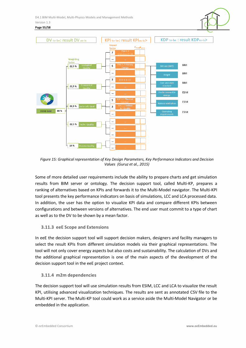
D4.1 BIM Multi-Model, Multi-Physics Models and Management Methods
Version 1.3
Page 55/58
© eeEmbedded Consortium www.eeEmbedded.eu
Figure 15: Graphical representation of Key Design Parameters, Key Performance Indicators and Decision Values (Guruz et al., 2015)
Some of more detailed user requirements include the ability to prepare charts and get simulation
results from BIM server or ontology. The decision support tool, called Multi-KP, prepares a
ranking of alternatives based on KPIs and forwards it to the Multi-Model navigator. The Multi-KPI
tool presents the key performance indicators on basis of simulations, LCC and LCA processed data.
In addition, the user has the option to visualize KPI data and compare different KPIs between
configurations and between versions of alternatives. The end user must commit to a type of chart
as well as to the DV to be shown by a mean factor.
3.11.3 eeE Scope and Extensions
In eeE the decision support tool will support decision makers, designers and facility managers to
select the result KPIs from different simulation models via their graphical representations. The
tool will not only cover energy aspects but also costs and sustainability. The calculation of DVs and
the additional graphical representation is one of the main aspects of the development of the
decision support tool in the eeE project context.
3.11.4 m2m dependencies
The decision support tool will use simulation results from ESIM, LCC and LCA to visualize the result
KPI, utilising advanced visualization techniques. The results are sent as annotated CSV file to the
Multi-KPI server. The Multi-KP tool could work as a service aside the Multi-Model Navigator or be
embedded in the application.

D4.1 BIM Multi-Model, Multi-Physics Models and Management Methods
Version 1.3
Page 56/58
© eeEmbedded Consortium www.eeEmbedded.eu
Outlook
In D4.2 the energy system concept will be elaborated within the urban design phase based on the
user requirements, the energy related neighbourhood and the resulted architectural draft. The
Energy System Information Model (ESIM) describes all parts of the energy system and subsystem
including parts and aspects of HVAC and BACS components. It contains also links to architectural
objects, HVAC, BACS components because those are modelled within IFC. The structure of the
ESIM follows the modularized concept of energy systems.
In D4.3 the general concept for the Link Model which was developed in the Mefisto project will be
used as baseline for interlinking the BIM domain models and eeeBIM models, like climate and
user behaviour models, BACS and ESIM. The eeBIM methodology which was developed in the
HESMOS project will be applied as a starting point. The different kinds of links will be identified
based on the information identified in this deliverable and in D4.2. The related different types of
relations and relationship objects will be developed and the requirements for the link attributes
and the transformation and mapping functions will be defined.
D4.4 is dedicated to the Multi-Model Manipulation. This deliverable will therefore give an
overview of the manipulation types and the environments they are executed in, that are for
example data models, repositories and servers. The manipulation will be realized via manipulation
services. They support the use cases presented in WP1 and will be listed and linked to the use
cases accordingly. D4.4 will also cover the according software implementation and its
documentation.
In D4.5 the filtering of Multi-Models will be covered in detail. Filtering is needed in nearly any kind
of model management and information handling, for example to prepare the BIM for the link
models. To link external non-BIM model data with BIM elements, the necessary BIM elements
have to be filtered first from the BIM. A modularized filtering approach will be used based on the
filter toolbox developed in the Mefisto project, which will be further extended and adapted for
eeE. The modules will be structured in 3 layers: meta data layer, semantic data layer and end-user
query layer. The modularisation allows re-using and adjusting the filter modules to the three
identified generic use cases. This existing filter toolbox will be extended in D4.4 by new ee-
functionalities, ee-query modules and the modules needed for the new ESIM and BACS semantic
model and the BACS data format.
D4.5 will address the Multi-Model Container, an approach for the exchange of interlinked data
from different AEC domains. The Multi-Model Container combines different domain models as so
called elementary models and link models and allows connecting construction elements from the
BIM model with other models, elements or files. Although the term container suggests it, the
elementary models and the link models are not necessarily encapsulated in such a container but
can remain in their respective model repositories, bound together by respective meta data
(tentatively planned to be implemented in RDF format). In this context, container is a rather
abstract term describing its enveloping functionality. Another possibility is a combination of both
approaches where for example some models are contained while others are stored on a server. In
D4.5 the definite architecture and software implementation of the Multi-Model Container in the
eeE context will be presented.

D4.1 BIM Multi-Model, Multi-Physics Models and Management Methods
Version 1.3
Page 57/58
© eeEmbedded Consortium www.eeEmbedded.eu
References
Bazjanac V., Maile T., O'Donnell J., Rose C., Marzovic N. (2011); Data Environments and processing in semi-automated simulation with EnergyPlus, Proceedings of the CIB W78-W102 2011: International Conference –Sophia Antipolis, France, (2011) 26-28 October.
Calleja-Rodriguez G. & Guruz R. (2014); eeEmbedded Deliverable D1.3: Interoperability and collaboration requirements © eeEmbedded Consortium, Brussels.
Crawley D. B. (1998); Which Weather Data Should You Use for Energy Simulations of Commercial Buildings?, ASHRAE Transactions, Vol. 104, Pt. 2, pp. 498?515.
DIN EN 15232 - Energy performance of buildings – Impact of Building Automation, Controls and Building Management. German version FprEN 15232:2011.
DIN EN ISO 16484 - Building automation and control systems (BACS) -- Part 3: Functions.
East B., Carrasquillo-Mangual M.(2012); The COBie Guide: a commentary to the NBIMS-US COBie standard, Available from http://projects.buildingsmartalliance.org/files/?artifact_id=4994.
eeEmbedded 2013-17, EU FP7 Project No. 609349. eeEmbedded [online], http://www.eeEmbedded.eu.
eeEmbedded: Description of Work, EU Project eeEmbedded, Grant No. 609349, Version 2013-06-13, Brussels.
eu.bac – Certifying Energy Efficiency of Building Automation and Control Systems, a first delivery and during the lifetime – Part 4: Specification of Key Performance Indicators.
Forejt L., Hensen J. L. M., Drkal F. & Barankova P. (2006); Weather data around the world for the design of field hospital HVAC, Proc. 17th Int. Air Conditioning and Ventilation Conference, Prague, CZ.
Frost & Sullivan (2010); European Building Automation Systems Market -Paving the Way for Smart and Energy Efficient Buildings.
FSGIM (2015); Facility Smart Grid Information Model [online], https://osr.ashrae.org/Public%20Review%20Draft%20Standards%20Lib/ASHRAE%20201%20APR%20Draft.pdf
Fuchs S. & Nityantoro E. (2013); BIM-Management von Multimodellen, Dresden: Technische Universität Dresden, Institut für Bauinformatik
gbXML (2014). Open Green Building XML. Available from: <www.gbxml.org>.
gbXML (2015). Open Green Building XML Schema: a Building Information Modeling Solution for Our Green World [online], http://gbxml.org
Geißler M.-C., Guruz R., van Woudenberg W. (2014); eeEmbedded Deliverable D1.1: Vision and requirements for a KPI-based holistic multi-disciplinary design, © eeEmbedded Consortium, Brussels.
Geißler M. C., Guruz R., van Woudenberg, W. (2014); eeEmbedded Deliverable D1.2: Use case scenarios and requirements specification, © eeEmbedded Consortium, Brussels.
Gudnason G., Katranuschkov P., Scherer R.J. & Balaras C.A., (2015); Framework for sharing and re-use of domain data in whole building energy simulation, ECPPM 2014, eWork and eBusiness in Architecture, Engineering and Construction – Martens, Mahdavi & Scherer (Eds), pp.495-202

D4.1 BIM Multi-Model, Multi-Physics Models and Management Methods
Version 1.3
Page 58/58
© eeEmbedded Consortium www.eeEmbedded.eu
Guruz R., Calleja G. & Geißler M.-C. (2015); eeEmbedded D2.1: Holistic multi-disciplinary KPI-based design framework, © eeEmbedded Consortium, Brussels.
Guruz R., Calleja G. & Geißler M.-C. (2015); eeEmbedded Deliverable D2.3: Holistic KPI based design methodology © eeEmbedded Consortium, Brussels.
IDD/IDF (2015); Energy Plus – Input-Output Reference [online], http://apps1.eere.energy.gov/buildings/energyplus/pdfs/inputoutputreference.pdf
ISO 10628: Diagrams for the chemical and petrochemical industry.
ISO 14617: Graphical symbols for diagrams.
Kadolsky M., Katranuschkov P., Dolenc M., Baumgärtel K., Klinc R. & Gudnason G. (2014); ISES Deliverable D3.1: Ontology specification, © ISES Consortium, Brussels.
Liebich T., Stuhlmacher K., Katranuschkov P., Guruz R.,Nisbet, N., Kaiser J., Hensel B., Zellner R., Laine T., Geißler M.-C. (2011); HESMOS Deliverable D2.1: “BIM Enhancement Specification2, © HESMOS Consortium, Brussels.
Modelica (2015); Introduction of OPENMODELICA [online], https://www.openmodelica.org/
O’Donnell J., See R., Rose C., Maile T., Bazjanac V. and Haves P. (2011); SimModel: A Domain Data Model for Whole Building Energy Simulation. In Proceedings of the 12th Conference of International Building Performance Simulation Association, Sydney, Australia, 14–16 November.
Scherer R. J. & Schapke S.-E. (eds.)(2014); Informationssysteme im Bauwesen – Modelle, Methoden und Prozesse (information Systems in Building Construction – Models, Methods and Processes), Springer Vieweg, DOI 10.1007/978-3-642-40883-0, 609 p.
See R., Haves P., Sreekanthan P., O’Donnell J., Basarkar M. and Settlemyre K. (2011); Development of a User Interface for the ENERGYPLUS™ Whole Building Energy Simulation Program. In Proceedings of the 12th Conference of International Building Performance Simulation Association, Sydney, Australia, 14–16 November.
Siemens AG (2012); Siemens entwickelt europäisches Architekturmodell für Smart Grids [online], http://www.siemens.com/press/de/pressemitteilungen/?press=/de/pressemitteilungen/2012/infrastructure-cities/smart-grid/icsg201205018.htm
Smith N., Merna T. & Jobling P. (2006); Managing risk in construction projects. Blackwell Publishing.
Solvik K., Kaiser J., Geißler M.-C., Stenzel P., (2014); eeEmbedded D1.4: Requirements for knowledge-based design support and templates, © eeEmbedded Consortium, Brussels.
SysML (2015); SysML Open Source Specification Project [online], http://sysml.org
VDI 3813 – Part 2 2011. Building automation and control systems (BACS) - Room control functions (RA functions). VDI, Beuth Verlag, Berlin.
VDI 6020 – Blatt 1 2001-05. Requirements on methods of calculation to thermal and energy
simulation of buildings and plants - Buildings. VDI, Beuth Verlag, Berlin.
Zellner R., Kaiser J. (2015); eeEmbedded Deliverable D2.2: Templates for fast semi-automatic detailing, © eeEmbedded Consortium, Brussels.
Zellner R., Guruz R., Mosch M., Katranuschkov P., Tøn A. & Kaiser J. (2015); eeEmbedded Deliverable D1.5: System Architecture of the virtual holistic design lab and office © eeEmbedded Consortium, Brussels.