Embed Size (px)
Citation preview

EE!ElMZL-C-24733(NAVY)
.31 August 1989
MILITARY SPECIFICATION
CONTROLLER INTERFACE UNIT, FIBER OPTIC (METRIC),GENERAL SPECIFICATION FOR
This specification is approved for use by the Department of the Navy,and is available for use by all Departments and Agencies of the
.Department of Defense.&
1. SCOPE
1.1 scoDe. This specification covers the requirements for a fiber opticcontroller interface (see 6.5.5) for use in Naval shipboard applications. Thecontroller interface, hereinafter referred to as the unit, shall provide fiberoptic transmission of command, interlock, safety, and indication siwals(see 6.5.9) between existing remote control panels and existing controllers.
1.2 Classification. Units covered by this specification are classified asspecified in 1.2.1 through 1.2,4 (see 3.1).
1.2.1 Fiber stvle. The fiber style designation defines the optical fiberused in the unit.
SK - Single-modeMM - Multimode
1.2.2 Fiber auantity. The fiber quantity defines the number of independentfiber channels (see 6.S.2).
.
Beneficial comments (recommendations, additions, deletions) and any pertinentdata which may be of use in improving this document should be addressed to:Commander, Naval Sea Systems Command, SEA 5523, Department of the Navy,Washington, DC 20362-5101 by using the self-addressed StandardizationDocument Improvement Proposal (DD Form 1426) appearing at the end of thisdocument or by letter.
AMSC N/A FSC 6030DISTRIBUTION STATEMENT A. Approved for public release; distribution is unlimited.
Downloaded from http://www.everyspec.com
MIL-C-24733(NAVY)
1.2.3 btical wavelength class. The optical wavelength class designationdefines the nominal center wavelength of operation of the fiber optic transmis-sion.
Class A - 1.31 micrometers (pm)Class B - 1.55 Nm
1.2.4 Electrical si~nal tvme. The electrical signal type designationdefines the type of electrical signal.
Type 1 - Analog (see 6.5.1)Type 2 - Digital (see 6.5.4)
42. APPLICABLE DOCUMENTS&
2.1 Government documents.
2.1.1 Specifications, standards. and handbooks. The following specifica-tions, s“t-andards,and handbooks form a part of this document to the extentspecified herein. Unless otherwise specified, the issues of these documents arethose listed in the issue of the Department of Defense Index of Specifications andStandards (DODISS) and supplement thereto, cited in the solicitation (see 6.2).
~PECIFICATIO.NS
FEDERALTT-I-735
MILITARYMIL-I-631
MIL-S-901
MIL-H-5606
MIL-T-5624
MIL-P-11268
MIL-P-15024
.
.
Q MIL-P-15024/5 -MIL-E-16400 -
MIL-F-16884 -MIL-L-17331 -
MIL-E-17555 -
Isopropyl Alcohol.
Insulation, Electrical, Synthetic-Resin Composi-tion, Nonrigid.
Shock Tests, H.I. (High-Impact) ShipboardMachinery, Equipment, and Systems, Requirementsfor.
Hydraulic Fluid, Petroleum Base; Aircraft, Missile,and Ordnance.
Turbine Fuel, Aviation, Grades JP-4, JP-5 andJP-5/JP-8 ST.Parts, Materials, and Processes Used in ElectronicEquipment.
Plates, Tags and Bands for Identification of Equip-ment.Plates, Identification.Electronic, Interior CommunicationEquipment, Naval Ship and Shore:cation for.
Fuel, Naval Distillate.Lubricating Oil, Steam Turbine andService.
and NavigationGeneral Specifi-
Gear, Moderate
Electronic and Electrical Equipment, Accessories,and Provisioned Items (Repair Parts): Packagingof’.
2
Downloaded from http://www.everyspec.com
1i
MIL-C-24733(NAVY)
MILITARY (Continued)MIL-E-21981 -
MIL-I-23053 -
MIL-L-23699 -
MIL-C-24621 -
fMIL-R-24720 -
MIL-T-24721 -4&
MIL-C-24733/l -
1MIL-C-28754 -
-.MIL-C-28859 -
MIL-T-55164 -
MIL-C-85045 -
MIL-C-85045/14 -
Electronics ~quipment, Nomenclature, SerialNumbers and Identification Plates: Requirements
for.Insulation Sleeving, Electrical, Heat Shrinkable,General Specification for.
Lubricating Oil, Aircraft Turbine Engine,Synthetic Base.
Couplers, Passive, Fiber Optic, General Specifi-cation for.
Receivers, Digital, Fiber Optic, Shipboard,General Specification for.
Transmitters, Digital, Fiber Optic, Shipboard,General Specification for.
Controller Interface Unit, Fiber Optic, 2 Fiber
Channels, Multimode Fiber (Metric).Connectors, Electrical, Modular, and ComponentParts General Specification for.
Connector Component Parts, Electrical Backplane,Printed Wiring, General Specification for.
Terminal Boards, Molded, Barrier Screw and StudTypes, and Associated Accessories, GeneralSpecification for.
Cable, Fiber Optic, Shipboard (Metric) General
Specification for. .Cable, Fiber Optic, Fiber Optic Cable Configura-tion Type.B (Pigtail), Optical Fiber Type MM(Graded Index, Glass Core and Glass Cladding,Multimode) (Metric).
STANDARDS
MILITARYMIL-STD-104 - Limits for Electrical Insulation Color.MIL-STD-129 - Marking for Shipment and Storage.MIL-STD-167-1 - Mechanical Vibrations of Shipboard Equipment (Type
MIL-STD-202
MIL-STD-454
MXL-STD-461
MIL-STD-462
MIL-STD-690MIL-STD-790
M1L-STD-81O
MIL-STD-965
I - Environmental and Type II - InternallyExcited).
Test Methods for Electronic and ElectricalComponent Parts.Standard General Requirements for ElectronicEquipment.
Electromagnetic Emission and SusceptibilityRequirements for ehe Control of ElectromagneticInterference.
Electromagnetic Interference Characteristics,Measurement of.Failure Rate Sampling Plans and Procedures.Reliability Assurance Program for Electronic PartsSpecifications.
. Environmental Test Methods and Engineering Guide-lines.
- Parts Control Program.
I
3
Downloaded from http://www.everyspec.com

MIL-C-24733(NA~)
MILITARY ’(Continued)MIL-STD-1344 -MIL-STD-1378 -
MIL-STD-1399, -Section 300
MIL-STD-1399, -Section 070Part 1
DOD-STD-2167 -
HANDBOOKS
.MILITARY&
MIL-HDBK-217 -MIL-HDBK-472 -
Test Methods for Electrical Connectors.Requirements for Employing Standard ElectronicModules.Interface Standard for Shipboard SystemsElectric Power, Alternating Current. (Metric)Interface Standard for Shipboard Systems,D.C. Magnetic Field Environment (Metric).
Defense System Software Development.
Reliability Prediction of Electronic Equipment.Maintainability Prediction.
(Unless otherwise indicated, copies of federal and military specifications,standards, and handbooks are available from the Naval Publications and FormsCenter, (ATTN: NPODS), 5801 Tabor Avenue, Philadelphia, PA 19120-5099.)
2.2 Non-Government Publications. The following document(s) form a part ofthis document to the extent specified herein. Unless otherwise specified, theissues of the documents which are DOD adopted are those listed in the issue of theDODISS cited in the solicitation. Unless otherwise specified, the issues ofdocuments not listed in the DODISS are the issues of the documents cited in thesolicitation (see 6.2].
AMERICAN SOCIETY FOR TESTING AND MATERIALS (ASTM)F 1166 - Standard Practice for Human Engineering Designs for Marine
Systems, Equipment and Facilities.
(Application for copies should be addressed to the American Society forTesting and Materials, 1916 Race Street, Philadelphia, PA 19103.)
ELECTRONIC INDUSTRIES ASSOCIATION (EIA)455-6 - Cable Retention Test Procedure for Fiber Optic Cable
Interconnecting Devices. (DoD adopted)455-36 - Twist Test for Fiber Optic Connecting Devices.
(DoD adopted)
“(Application for copies should be addressed to the Electronic Industries?Lssociation, 2001 Eye Street, NW, Washington, DC 20006.)
(Non-Govertient standards and other publications are normally available fromthe organizations that prepare or distribute the documents. These documents alsomay be available in or through libraries or other informational services.)
2.3 Order of precedence. In the event of a conflict between the text ofthis document and the references cited herein (except for related specificationsheets) , the text of this document takes precedence. Nothing in this document,however, supersedes applicable laws and regulations unless a specific exemptionhas been obtained.
4
Downloaded from http://www.everyspec.com

!MIL-C-24733(NAVY)
3. REQUIREMENTS
.3.1 SDecificatiort sheets. The individual item requirements shall be as
specified herein and in accordance with the applicable specification sheet. Inthe event of any conflict between the requirements of this specification and thespecification sheet, the latter shall govern.
3.2 First article. When specified (see 6.2), a samplefirst article inspection (see 6.3) in accordance with 4.4.
3.3 Reliability. Reliability of items furnished under
shall be subjected to
this specificationshall be established and maintained in accordance with the procedures and require-ments specified in MIL-sTD-790 and MIL-STD-690.
.&
3.3.1 Reliabil.icv requirement. The quantitative reliability requirementsexpressed in mean time between failures (MTBF) (see 6.5.7), mean-cycle-between-failures (MCBF), or others, shall be as specified (see 3.1).
3.3:2 Reliability prediction. A qualitative reliability prediction in theform of an MTBF calculation shall be performed in accordance with MIL-HDBK-217.Failure rates shall be derived based on an application environment assuming “Navalsheltered” usage and an ambient thermal environment range as specified herein(see 3.9).
~.4 Ma5erials. The units shall be constructed of materials that will notproduce toxic, corrosive, or explosive by-products. Materials shall not haveadverse effects upon operational or maintenance personnel under all operationaland environmental conditions, nor cause degradation of equipment performance.
3.4.1 Recovered materials. Unless otherwise specified herein, all materialincorporated in the products covered by this specification shall be new. Productsmay be fabricated using raw materials produced from recovered bulk materials tothe extent practicable if the intended use of the product is not jeopardized. Theterm “recovered materials” means materials which have been collected or recoveredfrom solid waste and reprocessed to become part of a source of raw materials, asopposed to virgin raw materials. None of the above shall be inte~-reted to meanthat the use of partially processed, assembled, used or rebuilt products areallowed under this specification.
- 3.4.2 Fibrous material. or~anic. Organic fibrous material shall be inaccordance with MIL-STD-454, requirement 44.
● 3.4.3 Flammable materials. Flammable materials shall be in accordance withMIL-STD-454, requirement 3.
3.4.4 Fragile or brittle materials. Cast iron, ebonite (hard vulcanizedrubber), asbestos, porcelain, and other similar materials shall not be used.
3.4.5 Fungus resistance (see 4.6.5.11. The unit shall be in accordance withMIL-STD-454, requirement 4, for fungus-inert materials. Units that are not inaccordance with MIL-STD-454, requirement 4, shall meet grade 1 classification ofMIL-STD-81O, method 508.
5
Downloaded from http://www.everyspec.com

MIL-C-24733(NAVY)
3.4.6 Hazardous material marking. When a unit is produced with hazardousmaterials, only as required (see 3.1), it shall be marked in-accordance with therequirements of public laws and regulations. The marking shall include asapplicable: name of product; quantity; warning symbol; signal word designatingdegree of hazard; affirmative statement of hazards; precautionary measurescovering actions to be followed or avoided; instructions in case of contact orexposure; antidotes and notes to physicians;’ instructions in case of fir@, spill,or leak; instructions for handling and storage; and disposal instructions.Marking of hazardous materials shall be in conformance with Federal HazardousSubstance Labeling Act.
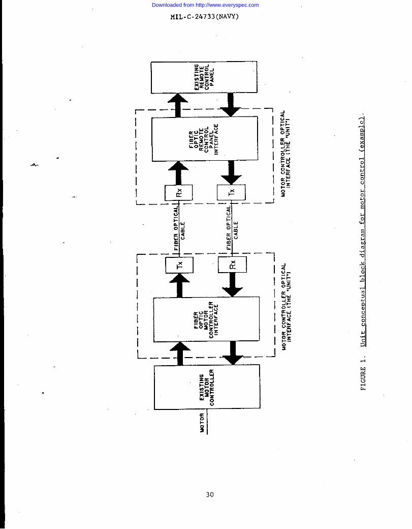
3.5 Desire. The unit shall provide fiber optic transmission of command,interlock, safety, and indication signals between existing remote control panelsand ~isting controllers via optical fiber transmission medium (cable). The unit
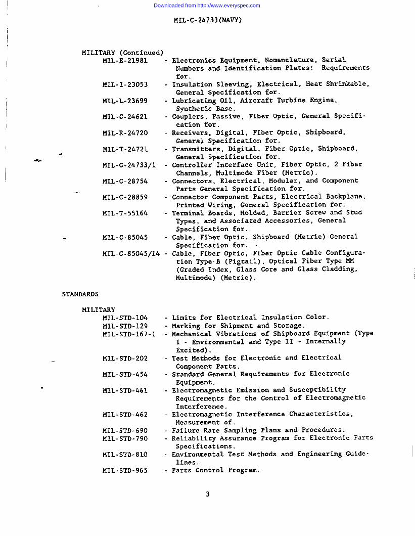
‘shall consist of two basic parts: fiber optic remote control panel interface andfiber optic controller interface (see figure 1). The unit circuits shall bedesigned such that a failure does not cause a change in state.
3.5;1 Fiber optic remote control panel interface. The fiber optic remotecontrol panel interface shall accept various types and numbers of input electricalsignals from the existing remote control panel and provide a composite time-division or frequency-division multiplexed electrical signal output compatiblewith the specified fiber optic transmitter. The fiber optic remote control panelinterfice shall also accept a time-division or frequency-division multiplexedelectrical signal from the specified fiber optic receiver and provide varioustypes and numbers of electrical signals compatible with the existing remotecontrol panel. Where applicable, the functions of this part of the unit may beincorporated into control consoles on special purpose electronic cards. Theseboards shall meet the performance requirements of this specification.
3.5.2 Fiber optic local controller interface. The fiber optic controller
interface shall accept a time-division or frequency-division multiplexed electri-cal signal from the specified fiber optic receiver and provide the electricalcommand signals compatible with the existing controller. The fiber optic con-troller interface shall also accept types and numbers of electrical indication
signals from the existing controller and provide a time-division or frequency-division multiplexed signal compatible with the specified fiber optic transmitter.
3.5.3 Firmware. If the design of the unit includes firmware, then thefifiware specifications shall conform to the requirements of DoD-STD-2167. NOsoftware shall be included in the unit design and operation.
● 3.6 Construction. The unit shall be of the construction and physicaldimensions as specified herein. Unless otherwise specified (see 3.1), all unitsshall use modular construction. The equipment modular construction shall conformto the standard hardware program module requirements specified in MIL-STD-1378.The selection of specific assembly design and packaging techniques shall reflectthe reliability and maintainability requirements of the individual unit specifica-tion sheet.
3.6.1 De~ree of enclosure. The type of enclosure shall be drip-proof orwatertight as specified (see 3.1).
6
Downloaded from http://www.everyspec.com

MIL-C-24733(NAVY)
3.6.2 Fiber optic ~i~tail. Units shall be supplied with fiber or cablepigtails as specified (see 3.1). One end of the pigtail shall be permanentlymounted in the unit housing, and the mounting construction shall provide strainrelief for the pigtail. The pigtail length shall be not less than 1 meter. Metalcomponents shall not be used within the pigtail, except for mounting to the unithousing or termination connector.
3.6.3 Terminals. The electrical connections and terminals, and the opticalconnections shall be in accordance with MIL-STD-454, requirement 19, and asspecified herein.
3.6.3.1 Terminal strength (see 4.6.2.11. The electrical terminals and theoptical interconnections shall show no evidence of breakage, loosening, or
-rela%ive motion between the electrical terminals or connectors and the body of theunit.
3.6.3.2 Solderabilitv [see 4.6.2.21. Terminal solderability shall be inaccordance with MIL-STD-454, requirement 5.
3.6.4 System modularization and accessibility. The modular construction ofthe items shall provide for replacement at the organizational level. Modularconstruction of che units shall be used to facilitate the removal and replacementof components and assemblies while minimizing the removal of ocher system com-ponents or assemblies. The unit shall be in accordance with MIL-STD-454, require-ment 36.
3.6.5 Standardization and interchan~eability. The units shall be con-structed to minimize the quantity of special tools required for all levels ofmaintenance. Special tools are defined as those tools not listed in the FederalSupply Catalog. Copies of this catalog may be consulted in the office of cheDefense Contract Administration Services Management Area (DCASMA). Standardizedpiece parts shall be used wherever possible. Circuit card assemblies shall beconstructed to be interchangeable between the appropriate units. The constructionof the units shall enable the units to be functionally and physically interchange-ablewith
(sge
*(see
between different units of the same part number ~nd shall be in-accordanceMIL-STD-454, requirement 7.
3.6.6 Dimensions {see 4.6.11. The unit dimensions shall be as specified3.1).
3.6.7 Weiszht (see 4,6,1j-. Height shall be within the limits specified3.1).
3.6.8 Interconnect wire color (see 4.6.l.).. Interconnect wire color shall bein accordance with MIL-STD-104, or as specified (see 3.1).
3.6.9 Finish (see 4.6.1~. The unit housing finish shall noc affect thelegibility of the unit part number and required markings over the life of theunit. The finish on all units shall be in accordance with MIL-E-16400.
3.6.10 Hardware. Unit hardware and unit mounting hardware shall conform toMIL-E-16400 and shall be selected to support unit requirements for electromagneticinterference (EMI) and electromagnetic compatibility (l?.MC)and durability.
7
Downloaded from http://www.everyspec.com

MIL-C-24733(NAVY)
3.6,10’.1 Printed-wiring and printed-wirimz assemblies. Printed wiring andprinted wiring assemblies used in the construction of the unit shall be inaccordance with MIL-STD-454, requirement 17.
3.6.10.2 Circuit card edge connectors. Circuit card edge connectors shallbe in accordance with MIL-C-28754 or MIL-c-28859.
3.6.10.3 Encapsulation and embedment. Unless otherwise specified (see 3.1),the unit shall be in.accordance with MIL-STD-454, requirement 47.
3.6.10.4 Internal wirinz Dractices. Internal wiring practices shall be inaccordance with MIL-STD-454, requirement 20.
‘3.6.1O.5 Microcircuit devices. Integrated circuits and hybrid devices used+ in the unit shall be in accordance with MIL-STD-454, requirement 64.
3.6.10.6 Semiconductor devices. Semiconductor devices used in the unitshall be in accordance with MIL-STD-454, requirement 30.
.“.
3.6.10.7 Fiber optic transmitters. Fiber optic transmitters used in theunit shall be as specified (see 3.1).
3.6.10.8 Fiber optic receivers. Fiber optic receivers used in the unitshall-be as specified (see 3.1).
3.6.10.9 Fiber optic couplers. Fiber optic couplers used in the unit shallbe in accordance withMIL-C-24621.
3.6.10.10 Fiber optic connectors. Fiber optic connectors used in the unitshall be as specified (see 3.1).
3.6.10.11 Fiber optic splices. Fiber optic splices used in the unit shallbe as specified (see 3.1).
3.6.10.12 Multi~lexers and demultiplexers. Multiplexer and demultiplexersused in the unit shall be as specified (see 3.1).
3.6.10.13 Switches and indication lights. Switches and indication lightsshall be as specified (see 3.1).
3.6.11 Electrical grounding. Exposed metal or other conducting parts shallbe at ground (ship’s hull) potential at all times.
●
3.6.12 Bonds and zrounds for inte~ral EMI sumression. Units shall beconstructed with adequate provisions for bonding the unit to a subsystem groundplane. Bonding shall not be accomplished through screws connecting the equipmentto mounting racks: Shock mounted units or those employing vibration isolatorsshall utilize bonding straps to bypass the shock mount or isolator to achieve alow impedance bond, 2.5 milliohms or less, between the equipment and subsystemground plane. Bonding jumpers shall be of the solid metal type and be as short aspossible. However, in no case shall the length to width ratio of the jumper be inexcess of 5 to 1. Bonding techniques employed shall not impede maintainabilitynor adversely affect interchangeability. Surfaces being bonded together shall beprepared by removing all anodic film, grease, paint, lacquer, dirt, or other
8
Downloaded from http://www.everyspec.com

MIL-C-24733(NAVY)
foreign and high resistance materials or agents from the immediate area to ensurenegligible radio frequency (RF) impedance between the adjac-t metal parts. Uponcompletion of the bonding assembly and ascertainment of the specified 2.5 milliohmor less bonding impedance, the completed assembly shall be refinished in accor-dance with the finish removed.
3.6.13 Conductor identification. Conductor identification shall be inaccordance with MIL-STD-454, requirement 20. Noninsulated wire leads in excess of10 centimeters (cm) in length shall be color coded by means of colored lacquerlocated near terminals, except when the leads terminate at marked terminals orwhen the terminal designations and the placement of the leads provide easy leadidentification.
“3.6.14 Terminal end identification. The ends of all conductors that‘terminate in lugs shall be clearly and permanently marked with the conductor
identification. Markings shall be made on white synthetic resin tubing conformingto MIL-I-631, type F, grade A, from U, class I, or polyvinyl chloride pressure-sensitive adhesive marking tape. Wire markings shall be clearly visible in cheassemble-d units. The tape markers shall be tightly wrapped with at least twoturns around the wire.
3.6.15 Human factors en~ineering. The units shall be designed and con-structed in accordance with ASTM F 1166, sections 33 through 40.
3.6.16 Selection of alternative materials. constructions. and Darts. All ofthe materials, processes, or parts required for the fabrication of the units shallbe selected in accordance with MIL-P-11268. Any item not in accordance withMIL-P-11268 shall be defined as a nonstandard part and shall be tested in accord-ance with nonstandard parts requirements as specified in MIL-STD-965. Proceduresfor obtaining approval for use of nonstandard items shall be in accordance withMIL-STD-454, requirement 22.
3.7 Performance. The following defines the prime power, interface charac-teristics, and optical performance parameters for the unit.
3.7.1 Prime power (see 4.6.3.11. The unit shall operate from prime powersources as specified (see 3.1).
3.7.1.1 Prime Dower variation - alternatin~ current (at) (see 4.6.3,11. Theunit shall operate within specified parameters defined in MIL-STD-1399, section300.
. 3.7.1.2 Prime Dower variation - direct current (de) (see 4.6.3. ~. The dcprime power variation requirements shall be as specified (see 3.1).
3.7.1.3 Current load (see 4.6,3.11. The unit shall not exceed worst-casecurrent load requirements as defined in the applicable specification sheet(see 3.1).
3.7.1.4 Reverse Polaritv Drotection. The unit shall provide reversepolarity protection for dc power inputs.
9
Downloaded from http://www.everyspec.com

MIL-C-24733(NAVY)
3.7.2 ~.
I 3.7.2.1 Remote control Danel interface.
1( 3.7.2.1.1 Analoz channels (from existiruz remote control Danellsee 4,6.3.2J. Analog channels interface parameters such as impedance, signal
levels, and equalization shall be as specified (see 3.1).
I3.7.2.1.2 Digital channels (from existin~ remote control Danel)
(see 4.6.3.2>. Digital signal interface parameters such as signal format, signalvoltage levels, rise and fall times, short circuit protection, and data rate(see 6.5.3) shall be as specified (see 3.1).
1- ‘3.7.2.1.3 Transmitter and receiver simals (see 4,6.3.2). The transmitterand receiver signals interface parameters shall interface directly with the fiberoptic receiver or the fiber optic transmitter specified (see 3.6.10.8 and3.6.10.7).
I 3.7~-2,2 Local control interface.
3.7.2.2.1 Analoz channels (to existing controller) (see 4.6.3.2).. Analogchannels interface parameters such as impedance, signal levels, and equalizationshall be as specified (see 3.1).
..
3.7.2.2.2 DiRital channels (to existiruz controller) (see 4.6.3.2J. Digitalsignal interface parameters such as signal format, signal voltage levels, rise andfall times, short circuit protection, and ‘data rate shall be as specified(see 3.1).
3.7.2.2.3 Transmitter and receiver simals {see 4.6.3.2). The transmitterand receiver signal interface parameters shall enable them to directly interfacewith the fiber optic receiver or the fiber optic transmitter specified(see 3.6.10.8 and 3.6.10.7).
3.7.3 Optical Performance Parameters.
3.7.3.1 Power margin (see 4.6.3.3.1)-. The power margin shall be asspecified (see 3.1).
3.7,3.2 Dvnamic ranve (see 4.6.3.3.21. The unit shall exhibit sufficientdynamic range to support operation under worst-case conditions established for~oth minimum and maximum path length configurations, including connectors andrepair splices, as specified (see 3.1). The unit shall function without degrada-tion in performance and without operator interference.
3.7.3.3 Data rate (see 4.6.3.3.3). The maximum data rate shall be asspecified (see 3.1).
3.8 Electrical breakdown Prevention.
3.8.1 Dielectric withstanding volta~e and insulation resistance (see 4.6.4,1
and 4.6.4.2). The remote and local units shall pass the specified insulationresistance and dielectric voltage withstanding tests. The insulation resistance
of the circuits shall be not less than 10 megohms when measured with the units at
10
Downloaded from http://www.everyspec.com

MIL-C-24733(NAVY)
&
.
ambient temperature of 25 degrees Celsius (“C). This requirement shall be netwithout resorting to either disassembly or disconnection of circuits, the shortingtogether of terminals, or the short-circuiting, by-passing, or grounding of partsor circuit elements during the test to prevent the test voltage from being appliedto parts. Such measures, however, may be used when specifically authorized in theaccepted test procedure for convenience and effectiveness in testing the units,provided such measures do not prevent the t~st from being effective on portions ofthe units. The remote and local units shall enable the required insulationresistance and dielectric withstanding voltage tests on the insulation system tobe performed without causing either incipient or catastrophic damage or signifi-cant (within acceptable product variability tolerance) degradation of any materialpart, including the electrical insulation. Furthermore, a defect in the insula-tion system shall not cause performance of either of the tests, when properlycon~ucted, to result in damage or degradation to any other material or pare exceptthat which may possibly be inflicted to the immediately adjacent parts separatedby the defective insulation.
3.13:2 Electrical creeDave and clearance distances (see 4.6.4.1 and 4.6.4.21.Clearances between any two electrical circuits or between any electrical circuitand ground (metal enclosures or chassis) shall meet the specified test conditionsfor insulation resistance and dielectric withstanding voltage. The minimumcreepage and clearance distances between electric circuits or between any electriccircuit and ground specified in MIL-STD-454, requirement 69, shall be met. Thevaluea shown in MIL-sTD-454, requirement 69, represent the desired minimumacceptable limits for nonarcing rigid construction in that they take intoconsideration only the average degree of enclosure and senice exposure. Toensure equipment reliability, minimum creepage and clearance distance shall beincreased as necessary, consistent with the minimum space and weight requirementsfor any of the following: where noninsulated parts are arc-rupturing; when anitem is not rigidly mounted; when an item is connected to higher voltage equip-ment; and when an item is subjected to exceptionally severe exposure.
3.8.3 Self-motection from inwt volta~e s~ikes (see 4.6.4.31. The unitshall continue proper operation with no degradation in performance.
3.9 Environmental requirements. The unit shall meet all requirementsspecified herein, during the specified operating environments and after thespecified storage environment. The operating temperature range and storagete.gperature
3.9.1performanceevidence of
range shall be as specified (see 3.1), as shon in table I.
TABLE 1. Temperature ramzes {ambient).
Range Operating (“C) Storage (“C)
1 -54 to +65 -62 to +71
2 -28 to +65 -62 to +71
3 -o to +50 -62 to +71
Temperature-humiditv cvclin~ (see 4,6,5.21. The unit shall meet therequirements over the operating temperature range. There shall be nophysical damage.
11
Downloaded from http://www.everyspec.com

MIL-C-24733(NAVY)
3.9.2 Salt fo~ (smav) (see 4.6.5.3). The units shall withstand the effectsof salt fog without sustaining any damage or degradation in performance. Inaddition, after completion of the tests and cleaning, the base metal of the unitshall not be visible through the finish or coating, nor shall there be anyevidence of blistering, softening, separation from the base metal, corrosionproducts, or other coating failure.
I3.9.3 Fluid irimersion (see 4.6.5.4). The unit shall reveal no swelling or
softening of materials and no loss of sealing capability or other effects detri-mental to the operation of the unit.
I 3.9.4 Shock (see 4.6.5.5). The units shall withstand the effects of shockwithout sustaining any damage or degradation in performance.
*
I&
3.9.5 Vibration (see 4.6.5.61. The units shall withstand the effects ofvibration without sustaining any damage or degradation in performance.
I 3.94-6 Inclination (see 4.6.5.7).. The units shall withstand the effects ofthe inclination test without sustaining any damage or degradation in performance.
3.9.7 Mametic field environment (see 4.6.5.8). The units shall be com-patible with the magnetic field environment interface constraints ofMIL-STD-1399, section 070, Part 1.
..
3.9.8 ExDlosive atmosphere (see 4.6.5,9). The unit shall safely operate inflammable atmospheres without causing an explosion.
3.9.9 Water drip (for clrip-moof enclosures onlv) (see 4.6.5.10). The unit .shall not reveal any water penetration into the sealed region of the unit.
3.9.10 Water pressure (for waterti~ht enclosures onlv) (see 4.6,5.11). Theunit shall reveal no penetration of indicator dye into the sealed region of theunit.
3.9.11 Nuclear radiation resistance (see 4.6.5.121. The units, includingelectronics and interconnecting wires and optical pigtails, shall withstand theeffects of nuclear radiation without sustaining any damage or degradation inperformance.
3.10 Mechanical requirements.
3.10.1 Compression resistance (see 4.6.6.11. The unit shall not deform more%han 1 percent from its largest cross-sectional dimension.
3.10.2 Imvact resistance (see 4.6.6.2)-. The unit shall not reveal anyphysical damage.
3.10.3 Cable seal flexing (see 4.6.6.3). Each strain relief mechanism shallprevent loss of environmental sealing or other damage that may impair the unitoperation.
Downloaded from http://www.everyspec.com
MIL-C-24733(NAVY)
3.10.4 Cable Dull-out force (see 4.6.6.4). The minimum cable pull-outstrength shall be 50 percent of the specified tensile strength of the attachedcable or 100 newtons, whichever is less. There shall be no evidence of cablejacket damage, cable clamp failure, seal damage, distortion or bending of metallicparts, or cable disengagement from the clamp.
3.10.5 Cable twist (see 4,6.6,51. The cable assembly shall reveal no damageor loss of environmental sealing.
3.11 Electroma metic interference SUPD xession.
3.11.1 Electromametic (see L.6,7~. The units shall meet the emission andsusceptibility requirements specified in MIL-STD-461, part 5 as specified
-(see+3.1). Above deck or below deck application shall be as specified (see 3.1).
3.11.2 Li~htnin~ (see 4.6.71. Input suppression and transient suppressionshall be incorporated into the unit to provide protection against lightningstrikes and current and voltage spikes.e.
3.11.2.1 ?nwts - ac (see 4.6,7). The units shall sustain no damage ordegradation in performance when subjected to voltage variations.
3.11.2.2 Power leads - dc (see 4.6.7>. The units shall sustain no damage ordegradation in performance when subjected to voltage variations.
3.12 Maintainability (see 6.5.61. Maintainability shall be in accordancewith MIL-STD-454, requirement 54 and as specified herein.
3.12.1 Quantitative maintainability requirements. The maintainabilityrequirement, expressed as the mean-time-to-repair (MTTR) (see 6.5.8), shall be asspecified (see 3.1).
3.12.1.1 MTTR The MTTR time figure includes localization (croubleshoocingto modular leve~~solacion, disassembly, modular replacement, reassembly, andcheckout of all corrective maintenance for restoration of system operation.
3.12.2 Maintainabilitv Prediction. Unless otherwise specified (see 3.1), amaintainability prediction shall be performed in accordance with MIL-HDBK-472,pr~cedure II, part A.
3.12.3 Maintainability desire criteria. Unless otherwise specified(see 3.1), maintainability design criceria shall be as follows:9
(a) Minimize the number and frequency of required preventive main-tenance actions.
(b) Provide adequate access to all components and minimize the require-ments for special tools and test equipment. Ensure that eachshipboard replaceable unit (SRU) shall be easily removable fromits chassis or cabinet without the use of special tools.
(c) Ensure that it shall be possible to perform ❑aintenance diagnosticswith power applied, equipment open and operating for intenals notexceeding 15 minutes at ambient temperatures.
I
13
Downloaded from http://www.everyspec.com

I
MIL-C-24733(NAVY)
(d) Ensure that preventive maintenance at the organizational level belimited to visual equipment inspections, lubricating mechanicalparts, cleaning surfaces and interiors, changing or cleaningfilters, and similar tasks necessary to ensure that the equipmentdoes not deteriorate with age and use. Preventive maintenance,involving removal and replacement of components (except filters),shall not be required at any level.
(e) Ensure that no intermediate level maintenance is required.(f) Incorporate Built-In-Tests.
3.13 Maintenance.
3.13.1 Maintenance levels. Three levels of maintenance exist for theequipment described in this specification: organizational, intermediate, and
- depot.
3.13.1.1 Organizational level. The units shall be designed to minimize thepreventive and corrective maintenance workload at the organizational level. Allrequired--maintenance actions shall be compatible with the Third Class InteriorCommunications Technician (IC3) skill level or as specified (see 3.1):
I 3.13.1.1.1 Corrective maintenance. Corrective maintenance actions shallconsist of SRU replacement at this level (see 3.12.1.1).
3.13.1.1.2 Preventive maintenance. Preventive maintenance at theorganizational level shall be limited to visual equipment inspections, lubricatingmechanical parts, cleaning surfaces and interiors, changing filters and similartasks necessary to ensure minimum equipment deterioration with age and use.Preventive maintenance shall not require the removal and replacement of components(except filters). Preventive maintenance requirements shall be grouped intoperiodic maintenance packages with the schedule interval maximized; the minimumallowable interval shall be greater than 90 days. Preventive maintenance shall beperformed by one person. Whenever preventive maintenance is in progress, it shallbe possible to restore the equipment to operational condition within 5 minutes.Requirements for preventive maintenance shall be such that a l-month delay inperforming the task will not adversely affect the operational performance of, orcause irreparable damage to, the unit.
3.13.1.2 DeDot level. The repair procedures, processes, materials, tools,and”special purpose electronic test equipment, required for corrective maintenanceof’the unit at the depot level, shall be determined by the Logistic SupportAnalysis (LSA). The units shall be designed to preclude the need for preventivemaintenance at the depot level.
3.14 Safety. The handling, installation, and operation of the items shallnot endanger personnel by direct contact or by long-term effects due to deteriora-tion of any component within the unit construction. The unit design and operationrequirements for safety shall implement and conform to the safety standards issuedby the Occupational’ Safety and Health Administration (OSHA) under the Secretary ofLabor.
14
Downloaded from http://www.everyspec.com

MIL-C-24733(NAVY)
3.16.1 Safetv eruzineering. Safety design criteria shall be in accordancewith MIL-STD-454, requirement 1, and MIL-STD-129 for labeling of safety hazards.
3.14.2 Terminals. Wire connections (bare terminals) shall use red polyo-Iefin sleeving in accordance with the requirements specified in MIL-I-23053 withnominal voltage and current type imprinted on sleeving.
3.14.3 Terminal striw. Terminal strips shall be covered by red,transparent, nonconductive barriers in accordance with MIL-T-55164 with nominalvoltage and current type identified. Small openings shall be provided (whereneeded) for maintenance.
3.14.4 Laser safetv. When laser transmitters are used (see 3.6.10.7), lasersaf@ty requirements shall be as specified (see 3.1).
3.14.5 Connector alimm ent. All electrical comeccors shall be providedwith aligning pins or equivalent devices to aid in alignment, to precludeinserting in other than the desired position, and to preclude electrical shock.-.
3.15 ~. When specified (see 3.1), the unit shall provide full datasecurity. The transmission security shall conform to the T~EST requirements asspecified (see 3.1).
3.16 Identification and markimt (see 4.6.1~.
3.16.1 Nomenclature (item name and tme desire ation~. Item name and typedesignation shall be established in accordance with the part numbering systemspecified in 6.8 and 6.9,
3.16.2 Serial numbers. Unless otherwise specified (see 3.1), serial numbersare required for each item level of the equipment to which an identification plateis to be applied and shall comply with the requirements of MIL-E-21981.
3.16.3 Marking. Marking of the equipment and items thereof shall be inaccordance with MIL-STD-454, requirement 67 and as specified herein. Unlessotherwise specified (see 3.1), marking shall conform to the normal se~icerequirements of MIL-P-15024 and MIL-P-15024/5.
3.16.4 Identification vlates (mouncin~ and location>. Identification platesand information plates shall be in accordance with MIL-P-15024 and MIL-P-15024/5,except that type G (adhesive backed plates) of MIL-P-15024 shall not be used.Plates shall be mounted in conspicuous space, generally on the front panel of the“item to which it applies. When space does not permit mounting on the front orfront panel, they may be mounted externally or internally in locations easilyaccessible. The Government assigned identification and serial numbers shall bepermanently marked on the units.
3.16.4.1 Material com~atibilitv. The maeerial selected for identificationp2ates and their fastening devices shall be compatible with the materials on whichthe plate is mounted.
Downloaded from http://www.everyspec.com

MIL,-C-24733(NAVY)
3.17 Workmanship (see 4.6.11. WorkmanshipMIL-STD-454, requirement 9.
4. QUALITY ASSWCE PROVISIONS
4.1 ResRonsibilitv for inspection. Unless
shall be in accordance
otherwise specified in
with
thecontract or purchase order, the contractor is responsible for the performance ofall inspecti~n requirements (examinations and tests) as specified herein. Exceptas otherwise specified in the contract or purchase order, the contractor may usehis own or any other facilities suitable for the performance of the inspectionrequirements specified herein, unless disapproved by the Government. The Govern-ment reserves the right to perform any of the inspections set forth in thisspecification where such inspections are deemed necessary to ensure supplies andserVices conform to prescribed requirements.
&
4.1.1 Responsibility for compliance. All items shall meet all requirementsof sections 3 and 5. The inspections set forth in this specification shall becomea part ~f the contractor’s overall inspection system or quality program. Theabsence of any inspection requirements in the specification shall not relieve thecontractor of the responsibility of ensuring that all products or suppliessubmitted to the Government for acceptance comply with all requirements of thecontract. Sampling inspection, as part of manufacturing operations, is anacceptable practice to ascertain conformance to requirements, however, this doesnot wthorize submission of known defective material, either indicated or actual,nor does it commit the Government to accept defective material.
4.2 Classification of inspections. The inspection requirements specifiedherein are classified as follows:
(a) First article inspection (see 4.4).(b) Quality conformance inspection (see 4.5).
4.3 Inspection conditions. Inspection conditions shall be met as specifiedin the applicable test method for each inspection parameter.
4.4 First article inspection. First article inspection shall consist of allthe tests listed in table 11. The units submitted shall be representative of theproduction process.
●
16
Downloaded from http://www.everyspec.com

4
&
●
MIL-C-24733(NAVY)
TABLE 11. Hz st article infmection.
Sample
Inspection Requirement Test method size
Group I
Dimensions 3.6.6 4.6.1 4
Weight 3.6.7 4.6.1 .l/
Finish 3.6.9 4.6.1 u
Conductor identification 3.6.13 4.6.1 u
Identification and 3.16 4.6.1 umarking
Workmanship 3.17 4.6.1 “u
Prime power 3.7.1 4.6.3.1 u
Interface 3.7.2 4.6.3.2 ucharacteristics
Power margin 3.7.3.1 4.6.3.3.1 u
Dynamic range 3,7.3.2 4.6.3.3.2 ‘u
Data rate 3.7.3.3 4.6.3.3.3 u
Group II
Terminal strength 3.6.3.1 4.6.2.1 1
Solderability 3.6.3.2 4.6.2.2 ~
Shock 3.9.4 4.6.5.5 1
Compression resistance 3.10.1 4.6.6.1 ~
Impact resistance 3.10.2 4.6.6.2 Y
See footnotes at end of table.
17
Downloaded from http://www.everyspec.com
&
*
MIL-C-24733(NAVY)
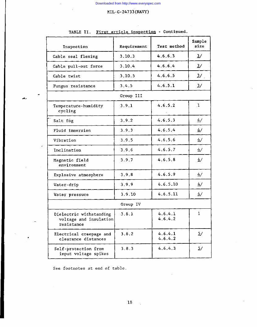
TABLE II. First article inspection - Continued.
SampleInspection Requirement Test method size
Cable seal flexing 3.10.3 4.6.6.3 ~
Cable pull-out force 3.10.4 4.6.6.4 ~
Cable twist 3.10.5 4.6.6.5 ~
Fungus resistance 3.4.5 4.6.5.1 ~
Group III
Temperature-humidity 3.9.1 4.6.5.2 1
cyc1ing
Salt fog 3.9.2 4.6.5.3 4/
Fluid immersion 3.9.3 4.6.5.4 w
Vibration 3.9.5 4.6.5.6 ~
Inclination 3.9.6 4.6.5.7 4/
Magnetic field 3.9.7 4.6.5.8 ~
environment
Explosive atmosphere 3.9.8 4.6.5.9 g
Water-drip 3.9.9 4.6.5.10 g
Water pressure 3.9.10 4.6.5.11 4/
Group IV
Dielectric withstanding 3.8.1 4.6.4.1 1
voltage and insulation 4.6.4.2
resistance
Electrical creepage and 3.8.2 4.6.4.1 wclearance distances 4.6.4.2
Self-protection from 3.8.3 4.6.4.3 Yinput voltage spikes
See footnotes at end of table.
Downloaded from http://www.everyspec.com

MIL-C-24733(NAVY)
TABLE II. First article inspection - Continued
I IInspection Requirement Test method
Electromagnetic 3.11 4.6.7interferencesuppression
Nuclear radiation 3.9.11 4.6.5.12
resistance
Samplesize
2/
& ~ All samples shall be submitted to group~ The same sample shall be used as in the
inspection.~ The same sample shall be used as in the
-.~ The same sample shall be used es in theinspection.
~ The same sample shall be used as in thevoltage inspection.
4.4.1 Samvle. A unit sample shall be submitted
I inspection.terminal strength
shock inspection.temperature-humidity
dielectric withstanding
for each unit constructionfor which first article approval is desired. The sample submitted shall be fourunits of the same part number.
4.4.2 Inspection routine. The sample shall be subjected to the inspectionsspecified in table 11 in the order shown. All sample units shall be subjected tothe inspection of group 1. The sample shall then be divided for testing in theremaining three groups. The sample units shall then be subjected to the inspec-tion for their particular group. After completion of sample testing, all unitsshall be restijected to group I testing. Any unit failing any inspection shallnot be subjected to further inspection.
4.4.3 Failures. One or more failures shall be sufficient cause for refusalto grant first article approval. When first article test units are taken from alarger lot, and the first article is disapproved, none of the units from that lotshall be delivered.
4.5 Oualitv conformance inspection. Quality conformance inspection shallconsist of the inspections and tests specified for group A inspection (table III),group B inspection (table IV), and group C inspection (table V), as specified*(see 6.4).
4..5.1 (koup A inspection. Group A inspections shall follow the order shownin table 111.
19
Downloaded from http://www.everyspec.com

MIL-C-24733(NAVY)
4
4..
TABLE III. GrouD A inspection.
Inspection Requirement Test method
Dimensions 3.6.6 4.6.1
Weight 3:6.7 4.6.1
Finish 3.6.9 4.6.1
Conductor identification 3.6.13 4.6.1
Identification and 3.16 4.6.1marking
Workmanship 3.17 4.6.1
Prime ,power 3.7.1 4.6.3.1.-
Interface 3.7.2 4.6.3.2characteristics
Power margin 3.7.3.1 4.6.3.3.1
.-Dynamic range 3.7.3.2 4.6.3.3.2
Data rate 3.7.3.3 4.6.3.3.3
4.5.2 Group B inspection. Group B inspection shall consist of the inspec-tions specified in table IV. Group B inspections shall be made on units that havepassed the group A inspection.
TABLE IV. Group B inspection.
.
Inspection Requirement Test method
Terminal strength 3.6.3.1 4.6.2.1
Solderability 3.6.3.2 4.6.2.2
Shock 3.9.4 4.6.5.5
Compression resistance 3.10.1 4.6.6.1
Impact resistance 3.10.2 4.6.6.2
Cable seal flexing 3.10.3 4.6.6.3
Cable pull-out force 3.10.4 4.6.6.4
Cable twist 3.10.5 4.6.6.5
20
Downloaded from http://www.everyspec.com

MIL-C-24733(NAVY)
4.5.3 Group C inspections. Group C inspections shall consist of theinspections in table V. Group C samples shall have satisfactorily completed a12group A and group B inspections. After completion of group C inspections, the&unples shal~ be-re-sub~ected to group A i~pection.
TABLE V. Groun C in Snection.
Requirement I TestInspection
3.4.5 I 4.6.5.1Fungus resistance
Temperature-humiditycycling
3.9.1 I 4.6.5.2
.
3.9.2 I 4.6.5.3Salt fog
Fluid immersion 3.9.3 I4.6.5.4
.
=-i-+=
Vibration
Inclination
Magnetic fieldenvironment
3.9.7 I 4.6.5.8
3.9.8 “ 4.6.5.9Explosive atmosphere
3.9.9 I 4.6.5.10Water-drip
3.9.10 I 4.6.5.11Water pressure
Nuclear’radiationresistance
3.9.11
I
4.6.5.12
3.8.1 4.6.4.14.6.4.2
Dielectric withstandingvoltage and insulationresistance
Electrical creepage andclearance distances
3.8.2 I 4.6.4.14.6.4.2
Self-protection frominput voltage spikes
3.8.3
I
4.6.4.3.
3.11 4.6.7Electromagneticinterferencesuppression
4.5.3.1 Disposition of samDle units. Sample units chat have failed shall
not be delivered,
21
Downloaded from http://www.everyspec.com

MIL-C-24733(NAVY)
4.6 Methods of inspection.
4.6.1 Visual and mechanical. Units shall be examined to verify that thematerial, dimensions, weight, color, finish, markings, and workmanship are inaccordance with the applicable requirements. Examinations shall be limited tothose that may be performed without disassembling the unit in such a manner thatits performance, durability, or appearance will be affected.
4.6.2 Desizn and construction.
4.6.2.1 Terminal strenzth (see 3.6.3.1). The terminals shall be tested inaccordance with MIL-STD-202-, method 211. Test condition A shall be used fortension, test condition D shall be used for twist, and test condition E shall beused7for torque. The load for test condition A shall be 4.5 kilograms (kg).
4.6.2.2 Solderabilitv (see 3.6.3.21. The terminals shall be tested inaccordance with MIL-STD-202, method 208.
4.6-;3 Performance.
4.6.3.1 Prime Rower. The unit shall be supplied with prime power and testedfor proper operation with prime power sources as specified (see 3.7.1). The acpower variation shall be in accordance with MIL-STD-1399, section 300.
4.6.3.2 Interface characteristics (see 3.7.2). The interface parameters
such as signal levels and rise and fall times shall be measured for the fiberoptic remote control panel interface and the fiber optic control interface. The
parameters measured and the test setup shall be as specified (see 3.1).
4.6.3.3 Optical Performance Parameters.
4.6.3.3.1 Power mar~in (see 3.7.3.11. The power margin shall be tested byinserting an attenuator equal to the required power margin into the fiber optictransmission path during the maximum path configuration of the system range test.
4.6.3.3.2 Dvnamic range (see 3.7.3.2). The dynamic range shall be verifiedby proper operation at the specified maximum and minimum optical path configura-tions.
4.6.3.3.3 Data rate (see 3.7.3.3). The maximum data rate shall be verifiedby proper operation at the specified maximum data rate.
● 4.6.4 Electrical breakdown prevention.
4.6.4.1 Insulation resistance (see 3.8.1 and 3.8.21. The insulationresistance of each electrically isolated circuit (see (b) (l), (2) below) withinthe unit shall be measured in accordance with MIL-STD-202, method 302. Thefollowing test conditions shall apply: ~
22
Downloaded from http://www.everyspec.com

MIL-C-24733(NAVY)
(a) Test potential: test condition B (high internal impedance).<b) Points of measurement: Between each electrically isolated circuit
(see (1) and (2) below) and another electrically isolated circuit,and between each electrically isolated circuit and ground.
(1) Electrically isolated circuits are those which have a mutualconnection only by means of electromagnetic coupling.
(2) Circuits whose only mutual connection is by means of a capaci-tor shall not be considered electrically isolated. Suchcircuits may be temporarily interconnected with a jumper wireonly when circuits are tested internally within the equip-ment.
. (c) Electrification time: Not less than 60 seconds.4P-
(d) The unit shouldbe operating during the test.
4.6.4.2 Dielectric withstanding voltage (see 3.8.1 and 3.8.2). Dielectricwithstanding voltages shall be measured in accordance with MIL-STD-202, method301. T%-ese measurements shall be made after all other tests have been completed.The following test conditions shall apply:
(a) Magnitude of test voltage.
(1) For circuits rated 60 volts or less, the root mean square(rms) test voltage shall be 900 volts.
(2) For circuits rated more than 60 volts but not greater than 600volts , the rms test voltage shall be twice rated circuitvoltage plus 1000 volts.
(3) For circuits rated above 600 volts, the rms test voltage shallbe 2% times rated circuit voltage plus 2000 volts.
(4) For circuits containing parts that are applied within theirspecified ratings and are in accordance with part specifica-tions that specify a lower dielectric test voltage thanspecified in (l), (2), or (3), the dielectric test voltagefor the circuit shall correspond to that spec$fied for thepart having the lowest specified dielectric test voltage, butin no case less than:
a. 900 volts for circuits connected to the power supplyterminals.
b. 500 volts for circuits electrically isolated from the powersupply terminals.
(b) Nature of test voltage: The test voltage shall approximate a truesine wave of a frequency not less than the rated frequency of thecircuit under test.
(c) Points of measurement: Between each electrically isolated circuitof the remote and local units (see 4.6.4.1, (b) (1), (2)), andbetween each such electrically isolated circuit and ground.
[d) Duration of test voltage application: Either of the following:
23
Downloaded from http://www.everyspec.com

MIL-C-24733(NAVY)
(1) Not less than 60 seconds. The test voltage shall not beabruptly applied to.or removed from any circuit. The applied
voltage shall be raised from O volts to the test voltage in asufficiently gradual manner to ensure the absence of voltagespikes and ovenoltages. Following test voltage application,the applied voltage shall be reduced to O volts in the samegradual manner.
(2) Not less than 1 second (as by means of a probe). Th}sduration shall be used only if it is determined that thesurges resulting from sudden application and removal of thetest voltage will not damage circuit components, and onlyunder the condition that the test voltage used is 20 percentgreater than that specified in (a) above.
.& (e) Definition of failure. Any evidence of arcing, corona (visible,
audible, or odorous), flashover, or punctured insulation shall beinterpreted as a failure of the test.
(f) Dielectric withstanding voltage tests shall be conducted after all-.other tests have been completed.
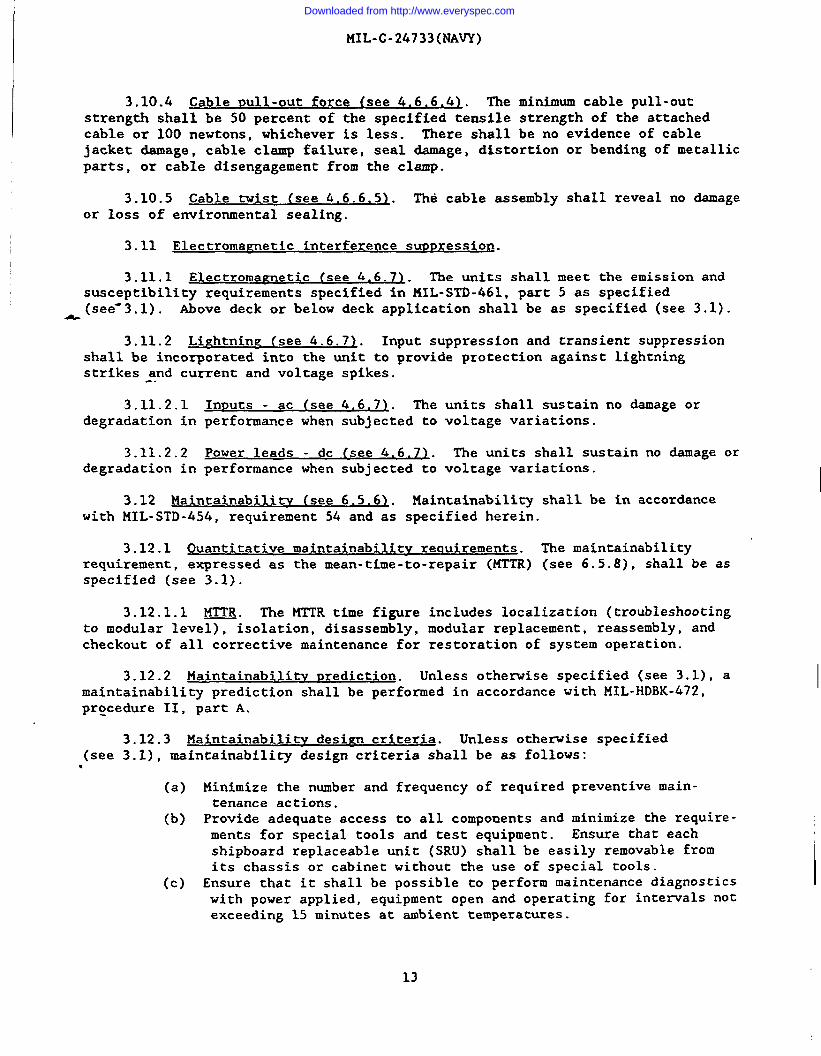
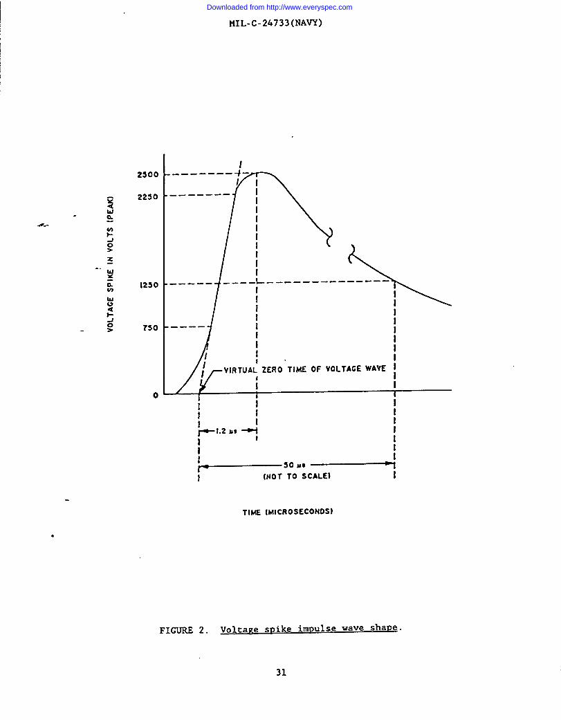
4.6,4.3 Self-protection from inDut voltage spikes (see 3.8.31. It shall beassumed that input voltage spikes up to 2500 volts are superimposed on the supplyvoltage (line-to-line or line-to-ground or both) having a basic impulse level(BIL).wave shape.as shown on figure 2. The unit shall be subjected to the inputvoltage spike as shown on figure 2. After the test, the unit performance shall beverified.
4.6.5 Environmental tests.
4.6.5.1 Funzus resistance (see 3.4.5). Units that do not meet the require-
ments of fungus-inert materials in accordance with MIL-STD-454, requirement 4,shall be tested by exposure to fungus in accordance with MIL-STD-81O, method 508.
4.6.5.2 Temperature-humidity cvclin~ (see 3.9.11. The unit shall be testedin accordance with MIL-STD-81O, procedure III, method 507. The temperature rangeshall be the specified operating range, andpercent.
4.6.5.3 Salt fog (smravl (see 3.9.2).daiicewith MIL-STD-81O, procedure I, method
4.6.5.4 Fluid immersion (see 3.9.31.
the relative humidity shall be 95
The unit shall be tested in accor-509, for 96 hours.
The unit shall be tested in accordancewith MIL-STD-202, method 215, except that the immersion fluids specified in tableVI shall be used for a period of 24 hours. Each unit shall be immersed in eachfluid and shall be completely dried before further testing.
24
Downloaded from http://www.everyspec.com

MIL-C-24733(NAVY)
.&
TABLE VI. @mersion test fluids .t
Test temperatureFluids Specification (“C)
Fuel oil MIL-F-16884 33 - 37
Turbine fuel (JP-5) MIL-T-S624 20 - 25
Isopropyl alcohol TT-I-735 20 - 25
Hydraulic fluids MIL-H-5606 48 - 50
Lubricating oils MIL-L-17331 73 - 77MIL-L-23699
Coolant ~ 20 - 25
-.Seawater 20 - 25
~ Monsanto Coolanol 25 or equivalent.
.4.6.5.5 Shock (see 3.9.4\. The unit shall be tested in accordance withMIL-S-901, grade A, type A, class I.
4.6.5.6 Vibration (see 3,9,51. The.unit shall be tested in accordance withtype I vibration test of MIL-STD-167-l.
4.6.5.7 Inclination (see 3.9.61. The unit shall be tested for verificationof inclination requirements by demonstration of operation under various inclina-tion angles up to and including a 60-degree angle.
4.6,5.8 Mametic field environment (see 3.9.7~ . The unit shall be tested inaccor&nce with the applicable test procedures in MIL-STD-462.
4.6.5.9 Exvlosive atmosphere (see 3.9.8~. The unit shall be tested inaccordance with MIL-STD-202, method 109, under conditions as specified (see 3.1).
4.6.5.10 Water-drip (see 3.9.91. The unit shall be placed beneath a drippan and subjected to continuously dripping water for 30 minutes. The drip panshall extend beyond all exposed sides of the unit and contain uniformly
“distributed spouts which produce both splashing and dripping. Each 129 squarecentimeters of the pan surface shall contain one spout. Each spout shall have adrip rate of 20 drops per minute.
4.6.5,11 Water nressure (see 3.9.101. The unit shall be immersed in anaqueous dye penetrant solution at an applied pressure of 0.1 megapascal (equiva-lent to a depth of 10.4 meters). The units shall be maintained at a temperatureof 10 co 35°C for 1 hour.
25
Downloaded from http://www.everyspec.com

MIL-C-24733(NAVY)
4.6.5.12 Nuclear radiation resistance (see 3.9.11)..shall be verified as specified (see 3.1). The dose ratesbe as specified (see 6.2).
4.6.6 Mechanical requirements inspection.
The unit performanceand exposure times shall
4.6.6.1 Compression resistance (see 3’.1O.I). The unit shall be tested asfollows. A force of 890 newtons shall be applied uniformly over each of its sidesand shall be maintained for 10 minutes. The test shall be performed at themaximum and minimum operating temperatures.
4.6.6.2 ImDact resistance (see 3.10.2>. The unit shall be fully operatingduring and after an impact test of 13.6 newton-meters at the specified maximum andminimum operating temperatures. The impact mass shall have a maximum radius of 10
*cm at the impact point.
4.6.6.3 Cable seal flexinz (see 3.10.3). The unit shall be tested inaccordance with MIL-sTD-1344, method 2017, with the exception that the test sampleshall be--a unit or unit component.
4.6.6.4 Cable Dull-out force (see 3.10.41. The unit shall be tested inaccordance with EIA 455-6. The axial tensile load shall be applied and maintainedfor 10 minutes.
~.6.6.5 Cable twist (see 3.10.5)-. The unit shall be tested in accordance
with EIA 455-36, with the exception that the test sample shall be a properlypigtailed unit. The tensile load shall be 5 newtons and the number of loads to beapplied shall be one.
4.6.7 Electromametic interference sumression (see 3.11). The unit shall
be tested for effects of electromagnetic emissions in accordance with MIL-STD-462
as specified (see 3.1).
4,8 Inspection of packa~in~ (see 5.1)-. Sample packages and packs, and theinspection of the presentation, packing, and marking for shipment shall be inaccordance with the requirements of section 5 and the documents specified therein.
5. PACKAGING
- (The packaging requirements specified herein apply only for direct Governmentacquisition. For the extent of applicability of the packaging requirements ofreferenced documents listed in section 2, see 6.7.)●
5.1 SDecific requirements. The requirements for preservation, packing, andmarking shall be in accordance with MIL-E-17555 or as specified (see 6.2).
5.1.1 Marking.
5.1.1.1 Standard marking. In addition to any special or other identifica-tion marking required (see 6.2), each unit supplementary, intermediate! andexterior container shall be marked in accordance with MIL-STD-129. The complete
26
Downloaded from http://www.everyspec.com

MIL-C-24733(NAVY)
military or contractor’s type or part number, as applicable (including the CAGE),shall be marked on all units, supplementary and intermediate packs in accordancewith the identification marking provisions specified in MIL-STD-129.
5.1.1.2 Special marking. All units, supplementary, intermediate andexterior containers, shall be marked as specified for sensitive electronic devicesin MIL-STD-129.
6. NOTES
(This section contains information of a general or explanatory nature chatmay be helpful, but is not mandatory.)
-6.1 Intended use. The unit is intended for use as a retrofit on existing‘equipment or as part of original design in new control applications. The unit is
intended to be used to provide communication over optical fibers between a remotecontrol panel and a local controller.
6.%- Acciuisition requirements. Acquisition documents must specify thefollowing:
(a)(b)
(c)
(d)(e)
(f)(g)(h)(i)
Title, number, and date of the specification.Issue of DODISS to be cited in the solicitation, and if required,the specific issue of individual documents referenced (see 2.1.1and 2.2).
Applicable specification sheet number, title, and date.When first article is required (see 3.2).Nuclear radiation dose rate and exposure times, when test isrequired (see 4.6.5.12).
Level of presentation and packing required (see 5.1).Special marking if required (see 5.1.1.1).Applicable part number (see 6.8).Quantity of units required.
6.3 First article. When first article inspection is required, che itemsshould be a first article sample. The first article should consist of 4 units.The contracting officer should also include specific instructions in acquisitiondocuments regarding arrangements for examinations, approval of first article testresults, and disposition of first articles. Invitations for bids should providethat the Government resemes the right to waive the requirement for samples forfirst article inspection to those bidders offering a product which has beenpreviously acquired or tested by the Government, and that bidders offering suchqxoducts, who wish to rely on such production or test, must furnish evidence withthe bid that prior Government approval is presently appropriate for the pendingcontract. Bidders should not submit alternate bids unless specifically requestedto do so in the solicitation.
6.3.1 LOC size. The lot size may be specified contractually, if desired.
27
Downloaded from http://www.everyspec.com

MIL-C-24733(NAVY)
6.4 Qualitv conformance inspections. Quality conformance inspectionsrequire contractual definition of the overall test program, including sampleand lot sizes, if appropriate (see 4.5).
6.5 Definitions.
sizes
6.5.1varies in a
6.5.2
6.5.3
Analo~ simal. An analog signal is a nominally continuous signal thatdirect correlation to the instantaneous value of a physical variable.
Channel. A channel is a path along which signals can be sent.
Data rate. Data rate is the aggregate signaling rate in the transmis-sion path of a data transmission system, usually expressed in bits per second.
4& 6.5.4 Digital simal. A digital signal is a nominally discontinuous elec-
trical signal that changes from one state to another in discrete steps.
6.5.5 Interface. Interface is a concept involving the interconnectionbetween-two devices or systems.
6.5.6 Maintainability. Maintainability is a characteristic of design andinstallation of an item expressed as the probability that an item will be retainedin or restored to a specific condition within a given period of time, when themaintenance is pqrformed in accordance with prescribed procedures and resources.
6.5.7 Mean-time-between-failures (MTBF1. MTBF, for a particular measurementinterval, is the total functioning life of a population of an item divided by thetotal number of failures within the population during the measurement interval.
6.5.8 Mean-time-to-repair (MTTR). MTTR is the total corrective maintenancetime, that is, the total time devoted to maintenance, divided by the total numberof corrective maintenance actions during a given period of time.
6.5.9 Sirnal. A signal is the code or pulse that represents intelligence,message, or control function conveyed over a communication system.
6.6 Provisioning. Provisioning Technical Documentation (PTD), spare parts,and repair parts should be furnished as specified in the contract,
- 6.6.1 When ordering spare parts or repair parts for the equipment covered bythis specification, the contract should state that such spare parts should meetthe same requirements and quality assurance provisions as the parts used in themanufacture of the equipment. Packaging for such parts should also be specified.
6.7 Subcontracted material and ~arts. The packaging requirements of refer-enced documents listed in section 2 do not apply when material and parts areacquired by the contractor for incorporation into the equipment and lose theirseparate identity when the equipment is shipped.
28
Downloaded from http://www.everyspec.com

MIL-C-24733(NAVY)
6.8 Part or Identifvinz Number (PINI . Units should contain only the
following:
D24733/ XX
Measurement system H Iunitbasic specification
Unitspecification sheet
Jidentification ~
Serial number
Examples:
‘“ D24733/01-001D24733/01-002
6.9 Part desimator. A part designator, if specified (see 3.1), should
include classifications (see 1.2) as follows:
(a) Fiber style (see 1.2.1).(b) Fiber quantity (see 1.2.2).(c) Optical wavelength class (see 1.2.3).(d) Electrical signal type (see 1.2.4).
Example: sMlA2 .
6.10 Specification use. Where MIL-C-24621 and MIL-C-85045 are referenced,the Navy versions, MIL-C-0024621 and MIL-C-0085045, should be used until canceled.
6.11 Subiect term (kev word) listing.
Fiber optic cableFiber optic communicationsFiber optic componentFiber optic receiverFiber optic transmitterPower marginRemote control panel
Review activities:Navy - EC, YD
Preparing activity:Navy - SH(Project 6030-NO05)
29
Downloaded from http://www.everyspec.com
.
w o
r.————
——1
I I 9 I I I t I
FIB
ER
oP
TIC
MO
TO
RC
ON
TR
OL
LE
RIN
TE
RF
AC
E
L.—
——
I
.——
——
——
.1
9I
IR
xk
F’B
yAB
yET
’c*L
tTx
—I
l—I
——
—-1
MO
TO
RC
ON
TR
OL
LE
RO
PT
ICA
LIN
TE
RF
AC
E[T
HE
●UN
IT”)
I 4I Ii I I f- 1L
——
.—
——
—J
MO
TO
RC
ON
TR
OL
LE
RO
PT
ICA
LIN
TE
RF
AC
E(T
HE
“UN
IT”)
FIGURE
1.
Unit
conceptual
block
dia~ram
formotor
control
(examPlel.
Downloaded from http://www.everyspec.com
MIL-C-24733(NAVY)
.
2s00
2250
0
----- --
—--- —--
-—---
\
—--- -— -- ---- —-
!1II————111i
VIRTUAL’ ZERO TIME OF VOLTAGE WAVE ~[1
I I 1I [
I I
! Ip-1.z at --l I
II I
II
so U8 +~ To ~cALE}i
TIME (MIcROSECONDS)
FIGURE 2. Voltage snike impulse wave sha~e.
31
Downloaded from http://www.everyspec.com

II
I
I
I
I
I!
II
STANDARDIZATION DOCUMENT IMPROVEMENT PROPOSAL(See lnsrrucrions - Rcvcrsc Side)
. DOCUMENT NUMBER 2.00 CUMENTTITLE CONTROLLER INTERFACE UNIT, FIBER OPTIC (METRIC),
MIL-C-24733(NAVY) GENEIblL SPECIFICATION FORkNAMEOFSU8MlTTlNG ORGANIZATION 4.7Y?EOF ORGAN12ATION fMuhwJ
u). ADORE”~(S&w~ CiIV,8t4&. ZtPCod8)
c1
VENOO13
El USE R
MANUFACTURER
❑ OTHER fb’prclfi): -
s
i. PROS1.EM AREAS
a Pw~@t Number ●nd Wordin~:
.
b. R.cemrn.ndd Wording:
C. R.uodR@ado fot Ruommonddon:
L REMARKS
fn. NAME OF SUBMITTER (ht. Fimt, Ml) - Optlond b. WORK TE LE?HONE NUMBER (lnehdt AweCodr) - Optlol-d
. MAILING ADDRESS (StuOk Clfv. Ststc. ZIP Codr) - ODtJWMI S. DATE OF SUBMISSION WYMMDD)
iID;“%.1426 ●REvIOU3 EDITION IS 0&30LET~
v
Downloaded from http://www.everyspec.com

..
.,.INSTRUCTIONS: In 8 continuing effort to make our standard-tion documents better, the DoD provides tbia form forusein
submitting comments and suggestions for improvements. All users of military standardization documents are invited to provide
suggestions. Thii form may be detached, folded along the lines indicated, taped along the loose edge (DO NOT STAPLE), and
mailed. In block 5, be as specific es possible about particular problem areas such as wording which required interpretation, was
tQO rigid, restrictive, loose, ambiguous, or was incompatible, and give proposed wording changes which would alleviate the
problems. Enter in block 6 any remarks not related to a specific paragraph of the document. If bhxk 7 is filled out, an
acknowledgement willbemailedtoyou within30 daystoletyouknow thatyourcommentswerereceivedandarebeingconsidered.
NOTE: This form may not be used to request copies of documents; nor to request waivers, deviations, or clarification of
specification requirements on current contracts. Comments submitted on this form do not constitute or imply authorization
to waive any portion of the referenced document($) or toamend contractual requirements.
(Fold along thb line)
.-
(Fold along this line)
DEPARTMENT OF THE NAVY
COMMANDER
NAVAL SEA SYSTEMS COMMAND ( SEA 5523)
DEPARTMENT OF THE NAVY 111111WASHINGTON , DC 20362-5101
OFFICIAL BUSINESSPENALTY FOR PRIVAIE USE S300 BUSINESS REPLY MAIL
FIRST CLASS PERMIT NO. 12503 WASHINGTON O C
POSTAGE WILL BE PAIO BY THE DEPARTMENT OF THE”NAVY
COMMANDER
NAVAL SEA SYSTEMS COMMAND ( SEA 55Z3 )
DEPARTMENT OF THE NAVY
WASHINGTON , DC 20362-5101
NO POSTAGENECESSARYIF MAILEO
IN THEUNITEO STATES
Downloaded from http://www.everyspec.com