Embed Size (px)
DESCRIPTION
EE/Econ 458 PF Equations. J. McCalley. NODE or BUS (substation). BRANCHES (lines or transformers). Power system representation. NETWORK (but unloaded and unsupplied). GENERATOR: Injects MW into the node. LOAD: Extracts MW out of the node (injects negative MW into the node). - PowerPoint PPT Presentation
Citation preview

EE/Econ 458PF Equations
J. McCalley
1

Power system representation
NODE or BUS(substation) BRANCHES
(lines or transformers)
NETWORK(but unloaded and unsupplied)
2
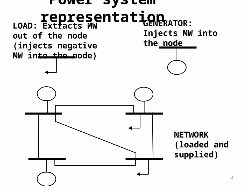
Power system representationLOAD: Extracts MW out of the node (injects negative MW into the node)
GENERATOR: Injects MW into the node
NETWORK(loaded and supplied)
3
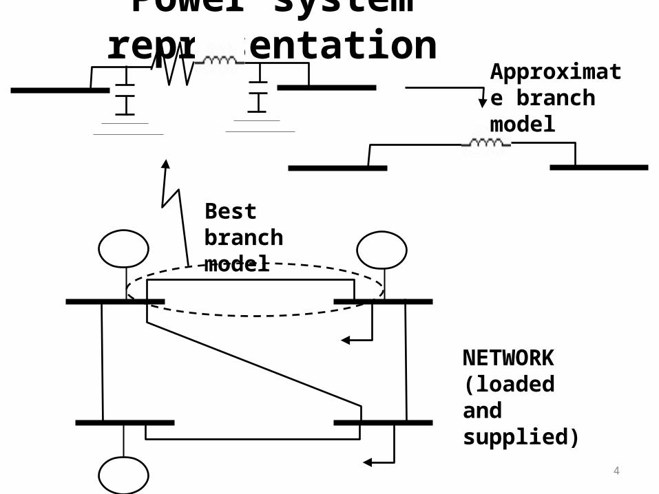
Power system representation
NETWORK(loaded and supplied)
Best branch model
Approximate branch model
4

Power system representation
Approximate branch model
Branch resistance Branch inductive reactance
Branch capacitive susceptance
Ignore resistance, OK because it is much less than reactance.Ignore susceptance, OK because its affect on MW flows very small.Only model reactance, OK for getting branch flows.
5

Power system representation
NETWORK(loaded and supplied)
Here is what we will model as a network (reactance only)
6
Power system representation
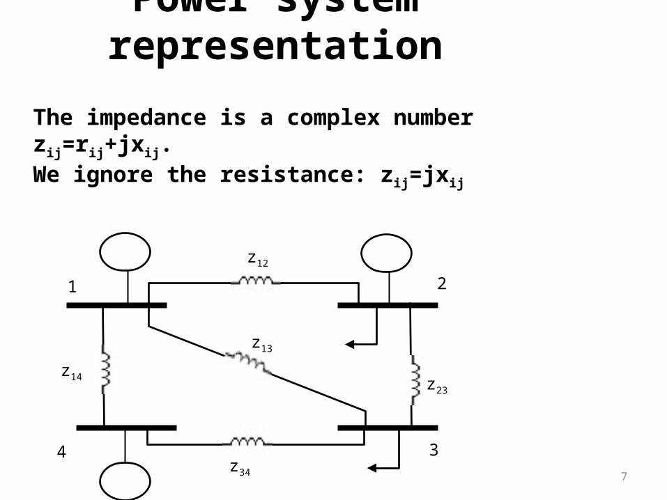
The impedance is a complex number zij=rij+jxij.We ignore the resistance: zij=jxij
7
1 2
34
z12
z14
z34
z23
z13

Power system representation
Impedance relates voltage drop and current via Ohm’s law:
)(1
jiij
ij VVz
I
i j
zij
Vi Vj
Iij
Voltage drop (volts)Current(amps)
8

Power system representation
Admittance, yij, is the inverse of impedance, zij:
)(1
jiij
ij VVz
I
i j
yij
Vi Vj
Iij
)( jiijij VVyI
9
Power system representation
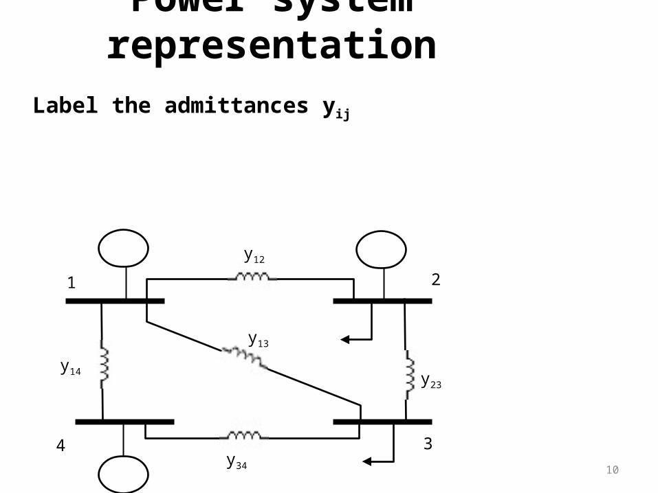
Label the admittances yij
10
y12
y14
y34
y23
y13
1 2
34

Power system representation
I1
Current injections: Ii flowing into bus i from generator or load.Positive if generator; negative if load.
11
y12
y14
y34
y23
y13
1 2
34
I2
I4
I3
I1, I4 will be positive.I3 will be negative.I2 will be positive if gen exceeds load, otherwise negative.

Power system representation
I1
Voltages: Vi is voltage at bus i.
12
y12
y14
y34
y23
y13
1 2
34
I2
I4
I3
V1V2
V3V4

Power system representation
I1
Kirchoff’s current law: sum of the currents at any node must be zero.
13
y12
y14
y34
y23
y13
1 2
34
I2
I4
I3
V1V2
V3V4
1413121 IIII
I14
I13
I12
Note:We assume there are no bus shunts in this system. Bus shunts are capacitive or inductive connections between the bus and the ground. Although most systems have them, they inject only reactive power (no MW) and therefore affect MW flows in the network only very little.

Power system representation
I1
Now express each current using Ohm’s law:
14
y12
y14
y34
y23
y13
1 2
34
I2
I4
I3
V1V2
V3V4
1413121 IIII
I14
I13
I12
)( jiijij VVyI
)()()( 4114311321121 VVyVVyVVyI

Power system representation
I1
Now collect like terms in the voltages:
15
y12
y14
y34
y23
y13
1 2
34
I2
I4
I3
V1V2
V3V4
I14
I13
I12
)()()( 4114311321121 VVyVVyVVyI )()()()( 14413312214131211 yVyVyVyyyVI

Power system representation
I1
Repeat for the other four buses:
16
y12
y14
y34
y23
y13
1 2
34
I2
I4
I3
V1V2
V3V4
I14
I13
I12
)()()()( 14413312214131211 yVyVyVyyyVI )()()()( 24423324232122112 yVyVyyyVyVI )()()()( 34434323133223113 yVyyyVyVyVI )()()()( 43443424134224114 yVyyyVyVyVI

Power system representationRepeat for the other four buses:
17
)()()()( 14413312214131211 yVyVyVyyyVI )()()()( 24423324232122112 yVyVyyyVyVI )()()()( 34434323133223113 yVyyyVyVyVI )()()()( 43443424134224114 yVyyyVyVyVI
Notes:1. yij=yji
2. If branch ij does not exist, then yij=0.
I1 y12
y14
y34
y23
y13
1 2
34
I2
I4
I3
V1V2
V3V4
I14
I13
I12
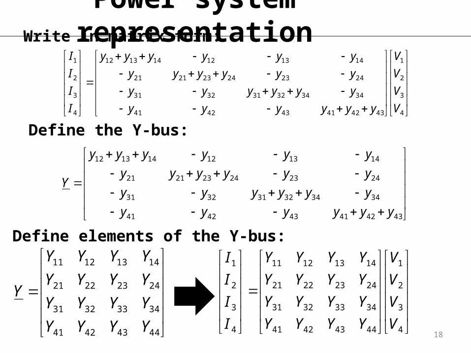
Power system representationWrite in matrix form:
18
Define the Y-bus:
4
3
2
1
434241434241
343432313231
242324232121
141312141312
4
3
2
1
V
V
V
V
yyyyyy
yyyyyy
yyyyyy
yyyyyy
I
I
I
I
434241434241
343432313231
242324232121
141312141312
yyyyyy
yyyyyy
yyyyyy
yyyyyy
Y
Define elements of the Y-bus:
44434241
34333231
24232221
14131211
YYYY
YYYY
YYYY
YYYY
Y
4
3
2
1
44434241
34333231
24232221
14131211
4
3
2
1
V
V
V
V
YYYY
YYYY
YYYY
YYYY
I
I
I
I
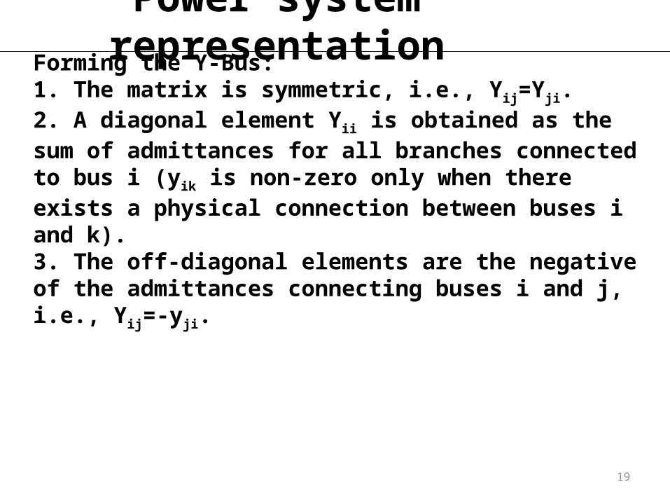
Power system representationForming the Y-Bus:1. The matrix is symmetric, i.e., Yij=Yji.2. A diagonal element Yii is obtained as the sum of admittances for all branches connected to bus i (yik is non-zero only when there exists a physical connection between buses i and k).3. The off-diagonal elements are the negative of the admittances connecting buses i and j, i.e., Yij=-yji.
19

Power system representationFrom the previous work, you can derive the power flow equations. These are equations expressing the real and reactive power injections at each bus. If we had modeled branch resistance, we would obtain:
20
N
jjkkjjkkjjkk
N
jjkkjjkkjjkk
BGVVQ
BGVVP
1
1
)cos()sin(
)sin()cos(
This requires too much EE, so forget about them. Let’s make some assumptions instead. But first, what is θk and θj?
where Yij=Gij+jBij.

Power system representation
21
N
jjkkjjkkjjkk
N
jjkkjjkkjjkk
BGVVQ
BGVVP
1
1
)cos()sin(
)sin()cos(
θk and θj are the angles of the voltage phasors at each bus.
The angle captures the time difference when voltage phasors cross the zero-voltage axis.In the time domain simulation, the red curve crosses before the blue one by an amount of time Δtand so has an angle of θ=ωΔt where ω=2πf and f is frequency of oscillation, 60 Hz for power systems.

Power system representationSimplifying assumptions:1.No resistance: Yij=jBij
2.Angle differences across branches, are small: θi-θj:• Sin(θi-θj)= θi-θj
• Cos(θi-θj)=1.03.All voltage magnitudes are 1.0 in the pu system.
22
This is the basis for the “DC power flow.”
N
kjj
jkkjk BP,1
)( Per-unit system:A system where all quantities are normalized to a consistent set of bases. It will result in powers being expressed as a particular number of “100 MVA” quantities. Admittance is also per-unitized.

Example
23
N
kjj
jkkjk BP,1
)(
y13 =-j10 y14 =-j10
y34 =-j10
y23 =-j10
y12 =-j10
Pg1=2pu
Pd3=4pu
Pd2=1pu
1 2
3 4
Pg2=2pu
Pg4=1pu
414114313113212112
4114311321121 )()()(
BBBBBB
BBBP
41431321211413121 BBBBBBP
Collect terms in the same variables
Repeat procedure for buses 2, 3, 4: 42432322423211212 BBBBBBP
43433432312321313 BBBBBBP
44342413432421414 BBBBBBP

Example
24
N
kjj
jkkjk BP,1
)(
y13 =-j10 y14 =-j10
y34 =-j10
y23 =-j10
y12 =-j10
Pg1=2pu
Pd3=4pu
Pd2=1pu
1 2
3 4
Pg2=2pu
Pg4=1pu
Now write in matrix form:
4
3
2
1
434241434241
343432313231
242324232121
141312141312
4
3
2
1
BBBBBB
BBBBBB
BBBBBB
BBBBBB
P
P
P
P

Example
25
Compare:
4
3
2
1
434241434241
343432313231
242324232121
141312141312
4
3
2
1
BBBBBB
BBBBBB
BBBBBB
BBBBBB
P
P
P
P
44434241
34333231
24232221
14131211
BBBB
BBBB
BBBB
BBBB
jY
434241434241
343432313231
242324232121
141312141312
bbbbbb
bbbbbb
bbbbbb
bbbbbb
j
2010010
10301010
0102010
10101030
jY
4
3
2
1
2010010
10301010
0102010
10101030
1
4
1
2

Example
26
4
3
2
1
2010010
10301010
0102010
10101030
1
4
1
2
1
4
1
2
2010010
10301010
0102010
101010301
4
3
2
1
But matlab indicates above matrix is singular which means it does not have an inverse.There is a dependency among the four equations, i.e., we can add the bottom three rows and multiply by -1 to get the top row. This dependency occurs because all four angles are not independent; we have to choose one of them as a reference with a fixed value of 0 degrees.
Example
27
1
4
1
2
2010010
10301010
0102010
101010301
4
3
2
1
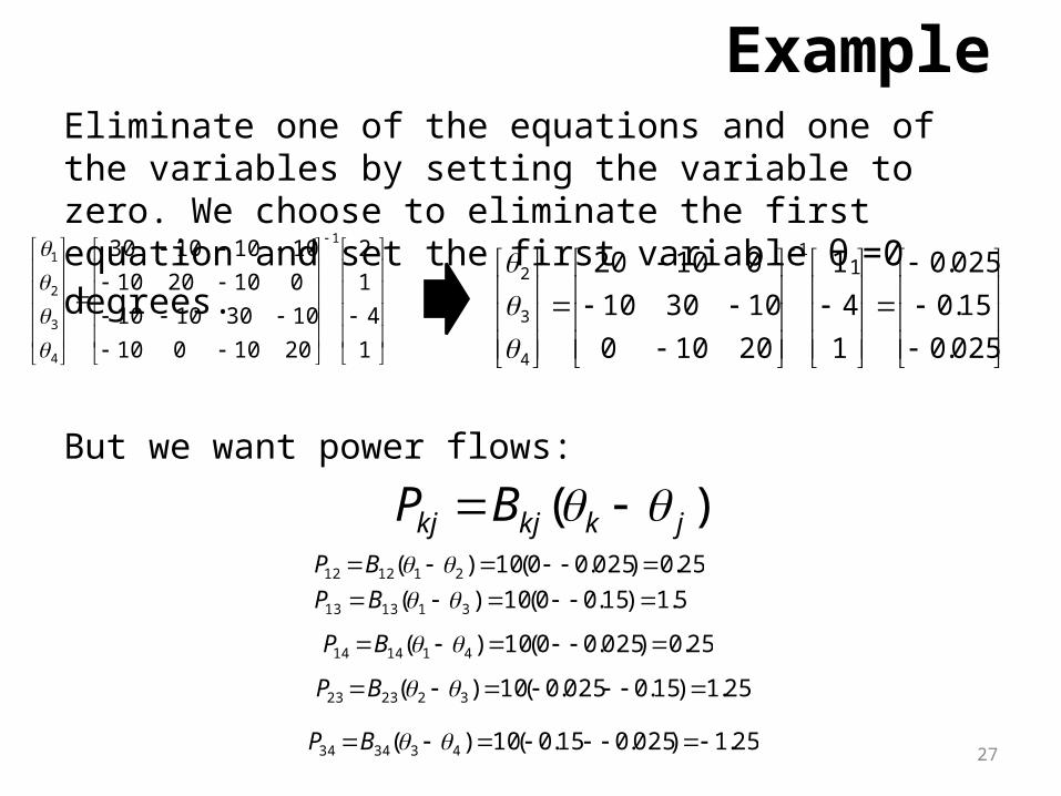
Eliminate one of the equations and one of the variables by setting the variable to zero. We choose to eliminate the first equation and set the first variable θ1=0 degrees.
025.0
15.0
025.0
1
4
1
20100
103010
010201
4
3
2
But we want power flows:
)( jkkjkj BP 25.0)025.00(10)( 211212 BP
5.1)15.00(10)( 311313 BP
25.0)025.00(10)( 411414 BP
25.1)15.0025.0(10)( 322323 BP
25.1)025.015.0(10)( 433434 BP

Example
28
Resulting solution:
P13=1.5 P14 =0.25
P43 =1.25
P23 =1.25
P12=0.25
Pg1=2pu
Pd3=4pu
Pd2=1pu
1 2
3 4
Pg2=2pu
Pg4=1pu

Example
29
Resulting solution:
P13=1.5 P14 =0.25
P43 =1.25
P23 =1.25
P12=0.25
Pg1=2pu
Pd3=4pu
Pd2=1pu
1 2
3 4
Pg2=2pu
Pg4=1pu

How to solve power flow problems
30
Develop B’ matrix:
4
3
2
1
434241434241
343432313231
242324232121
141312141312
4
3
2
1
BBBBBB
BBBBBB
BBBBBB
BBBBBB
P
P
P
P
44434241
34333231
24232221
14131211
BBBB
BBBB
BBBB
BBBB
jY
434241434241
343432313231
242324232121
141312141312
bbbbbb
bbbbbb
bbbbbb
bbbbbb
j
1. Get the Y-bus2. Remove the “j” from the Y-bus.3. Multiply Y-bus by -1.4. Remove row 1 and column 1.
2010010
10301010
0102010
10101030
jY
20100
103010
01020
'B

How to solve power flow problems
31
Develop equations to compute branch flows:
)( ADPB
where:•PB is the vector of branch flows. It has dimension of M x 1. Branches are ordered arbitrarily, but whatever order is chosen must also be used in D and A.•θ is (as before) the vector of nodal phase angles for buses 2,…N•D is an M x M matrix having non-diagonal elements of zeros; the diagonal element in position row k, column k contains the negative of the susceptance of the kth branch.•A is the M x N-1 node-arc incidence matrix. It is also called the adjacency matrix, or the connection matrix. Its development requires a few comments.

How to solve power flow problems
32
How to develop node-arc incidence matrix:
)( ADPB
• number of rows equal to the number of branches (arcs) and a number of columns equal to the number of nodes.
• Element (k,j) of A is 1 if the kth branch begins at node j, -1 if the kth branch terminates at node j, and 0 otherwise.
• A branch is said to “begin” at node j if the power flowing across branch k is defined positive for a direction from node j to the other node.
• A branch is said to “terminate” at node j if the power flowing across branch k is defined positive for a direction to node j from the other node.
• Note that matrix A is of dimension M x N-1, i.e., it has only N-1 columns. This is because we do not form a column with the reference bus, in order to conform to the vector θ, which is of dimension (N-1) x 1. This works because the angle being excluded, θ1, is zero.

How to solve power flow problems
33
5 1
4
3
2
Pg1=2pu
Pd3=4pu
Pd2=1pu
1 2
3 4
Pg2=2pu
Pg4=1pu
number branch
5
4
3
2
1
01-0
11-0
01-1
001-
1-00
A
4 3 2
number node
100000
010000
001000
000100
000010
D
4
3
2
100000
010000
001000
000100
000010
01-0
11-0
01-1
001-
1-00
)( ADPB

How to solve power flow problems
34
3
43
32
2
4
3
43
32
2
4
5
4
3
2
1
10
)(10
)(10
10
10
100000
010000
001000
000100
000010
B
B
B
B
B
P
P
P
P
P
025.0
15.0
025.0
4
3
2
5.1
25.1
25.1
25.0
25.0
5
4
3
2
1
B
B
B
B
B
P
P
P
P
P
P13=1.5 P14 =0.25
P43 =1.25
P23 =1.25
P12=0.25
Pg1=2pu
Pd3=4pu
Pd2=1pu
1 2
3 4
Pg2=2pu
Pg4=1pu


![Chapter 458-61A Chapter 458-61A WAC REAL …lawfilesext.leg.wa.gov/law/WACArchive/2013/WAC-458-61A...458-61A-101 Real Estate Excise Tax [Ch. 458-61A WAC—p. 2] (8/3/11) Legislation](https://img.pdfslide.us/doc/110x75/5fb4b3e18aff3f19c748349f/chapter-458-61a-chapter-458-61a-wac-real-458-61a-101-real-estate-excise-tax.jpg)


![INDEX [korea.kyocera.com] · CM03 (0201) Rated Voltage(Vdc) Capacitance 16 25 50 1R0 1.0 pF 1R5 1.5 pF 2R0 2.0 pF 3R0 3.0 pF 4R0 4.0 pF 5R0 5.0 pF 6R0 6.0 pF 7R0 7.0 pF 8R0](https://img.pdfslide.us/doc/110x75/5f468f04b73716507c2277fc/index-korea-cm03-i0201i-rated-voltageivdci-capacitance-16-25-50-1r0.jpg)