Embed Size (px)
Citation preview
EEE Parts Engineering:What Project Managers and Systems Engineers Should Know
Harry ShawNASA Goddard Space Flight Center
Greenbelt, MD
Jeannette PlanteDynamic Range Corporation
Seabrook, MD
Seminar Outline:Introduction: Why do Parts Engineering?
Center Policy Documents & Historical Perspective
Key terms and phrases
Risk Management
Current Technology Issues and Challenges
Radiation
Q&A/Wrap up
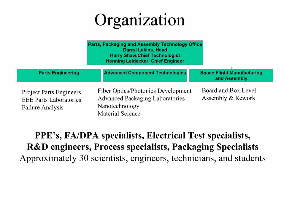
Organization
Parts Engineering Advanced Component Technologies Space Flight Manufacturingand Assembly
Parts, Packaging and Assembly Technology OfficeDarryl Lakins, Head
Harry Shaw,Chief TechnologistHenning Leidecker, Chief Engineer
Project Parts EngineersEEE Parts LaboratoriesFailure Analysis
Fiber Optics/Photonics DevelopmentAdvanced Packaging LaboratoriesNanotechnologyMaterial Science
PPE’s, FA/DPA specialists, Electrical Test specialists,R&D engineers, Process specialists, Packaging Specialists
Approximately 30 scientists, engineers, technicians, and students
Board and Box Level Assembly & Rework
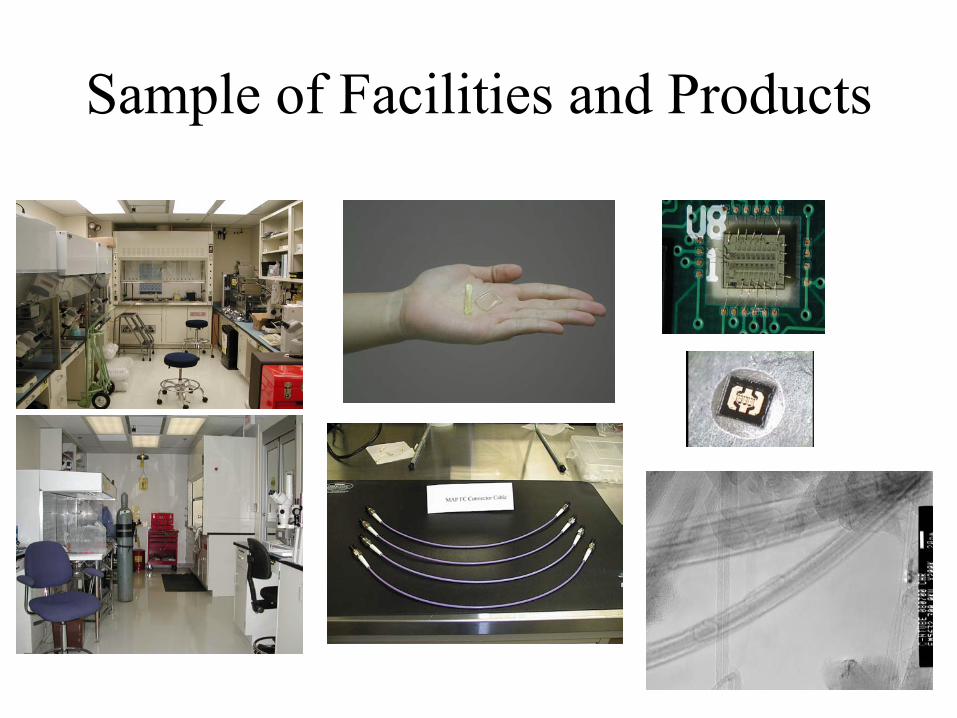
Sample of Facilities and Products
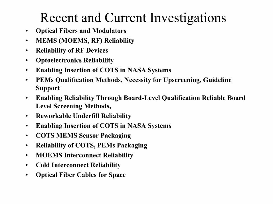
Recent and Current Investigations• Optical Fibers and Modulators • MEMS (MOEMS, RF) Reliability• Reliability of RF Devices• Optoelectronics Reliability• Enabling Insertion of COTS in NASA Systems• PEMs Qualification Methods, Necessity for Upscreening, Guideline
Support• Enabling Reliability Through Board-Level Qualification Reliable Board
Level Screening Methods, • Reworkable Underfill Reliability• Enabling Insertion of COTS in NASA Systems• COTS MEMS Sensor Packaging• Reliability of COTS, PEMs Packaging• MOEMS Interconnect Reliability• Cold Interconnect Reliability• Optical Fiber Cables for Space
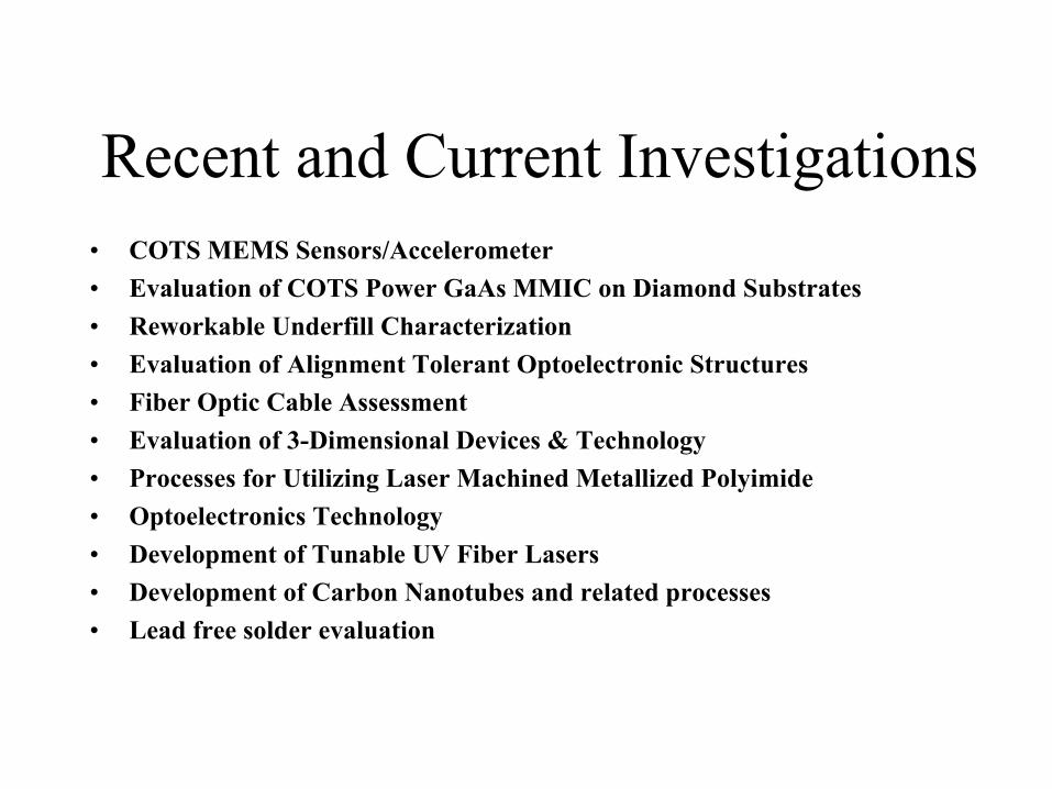
• COTS MEMS Sensors/Accelerometer • Evaluation of COTS Power GaAs MMIC on Diamond Substrates• Reworkable Underfill Characterization• Evaluation of Alignment Tolerant Optoelectronic Structures• Fiber Optic Cable Assessment• Evaluation of 3-Dimensional Devices & Technology• Processes for Utilizing Laser Machined Metallized Polyimide• Optoelectronics Technology• Development of Tunable UV Fiber Lasers• Development of Carbon Nanotubes and related processes• Lead free solder evaluation
Recent and Current Investigations
※
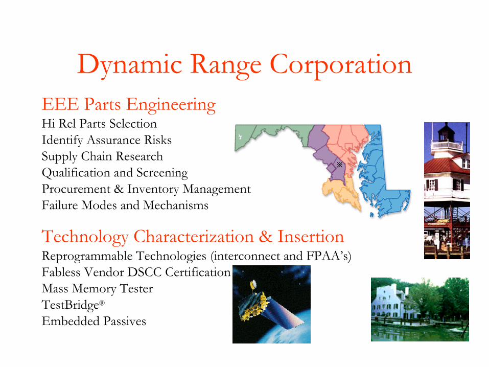
Dynamic Range CorporationEEE Parts EngineeringHi Rel Parts SelectionIdentify Assurance RisksSupply Chain ResearchQualification and ScreeningProcurement & Inventory ManagementFailure Modes and Mechanisms
Technology Characterization & InsertionReprogrammable Technologies (interconnect and FPAA’s)Fabless Vendor DSCC CertificationMass Memory TesterTestBridge®
Embedded Passives
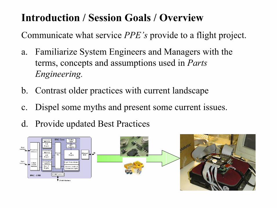
Introduction / Session Goals / OverviewCommunicate what service PPE’s provide to a flight project.
a. Familiarize System Engineers and Managers with the terms, concepts and assumptions used in Parts Engineering.
b. Contrast older practices with current landscape
c. Dispel some myths and present some current issues.
d. Provide updated Best Practices
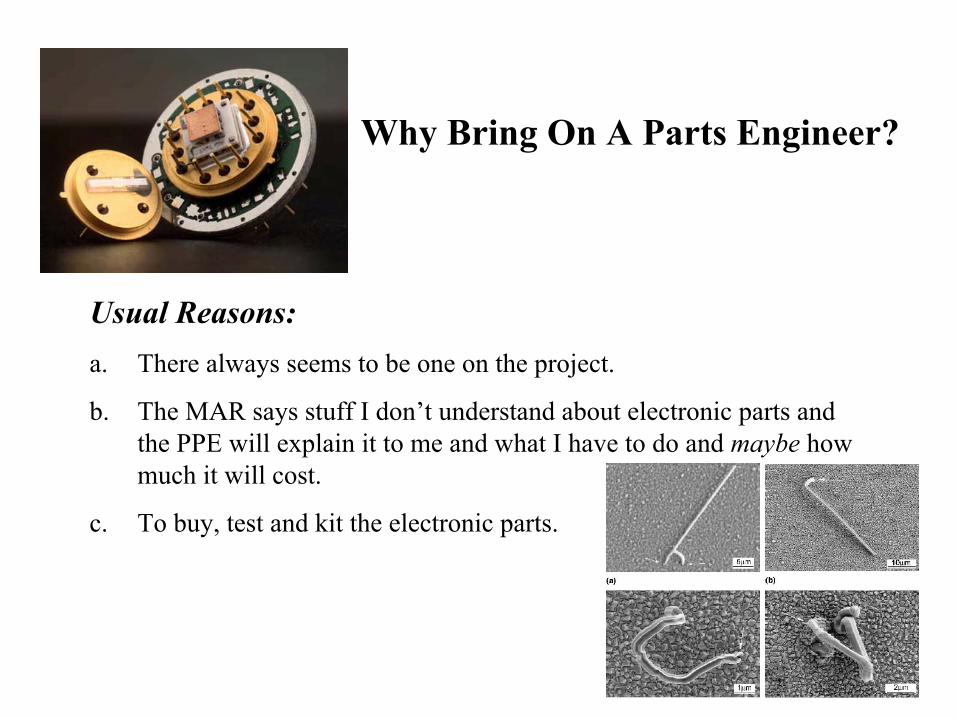
Why Bring On A Parts Engineer?
Usual Reasons:a. There always seems to be one on the project.
b. The MAR says stuff I don’t understand about electronic parts andthe PPE will explain it to me and what I have to do and maybe how much it will cost.
c. To buy, test and kit the electronic parts.
Better Reasons:a. To be pro-active about preventing part failure.
b. To avoid known and understood problems (specialized knowledge).
c. To avoid installing parts with common manufacturing defects.
d. To avoid parts whose assurance is not known (characterization)
e. To avoid the “sweet part” dilemma
f. To help the QE understand the quality and reliability of the parts being used. To define a parts control plan for the MAR.
g. To support Configuration Management
h. For Supply Chain Management
i. To coordinate failure investigations (electronic part related).
Why Bring On A Parts Engineer?
a. During Upgrading Testing (pre-installation): ($15,000 - $50,000 in parts and labor)
b. During System I &T:
($25,000 - $100,000 in parts and labor)
a. On the Launch Pad:(>$500,000 in parts, labor, investigators, launch support)
a. During the Mission:
(>50,000,000 lost science, reduced competitiveness)
What is the Value of Avoiding EEE Part Failure?
Priceless!!!
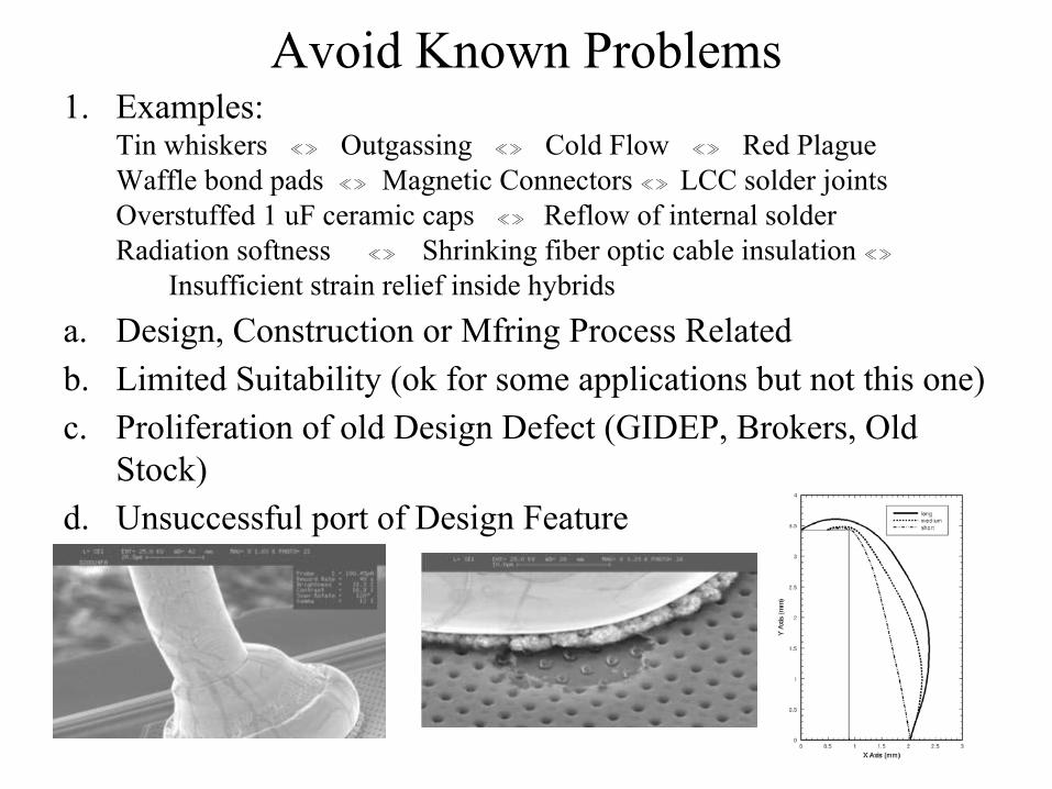
Avoid Known Problems1. Examples:
Tin whiskers ≪≫ Outgassing ≪≫ Cold Flow ≪≫ Red Plague Waffle bond pads ≪≫ Magnetic Connectors ≪≫ LCC solder jointsOverstuffed 1 uF ceramic caps ≪≫ Reflow of internal solder Radiation softness ≪≫ Shrinking fiber optic cable insulation ≪≫
Insufficient strain relief inside hybrids a. Design, Construction or Mfring Process Relatedb. Limited Suitability (ok for some applications but not this one)c. Proliferation of old Design Defect (GIDEP, Brokers, Old
Stock)d. Unsuccessful port of Design Feature
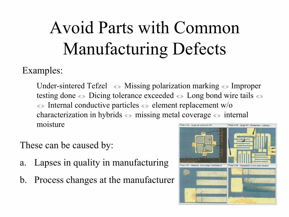
Avoid Parts with Common Manufacturing Defects
These can be caused by:
a. Lapses in quality in manufacturing
b. Process changes at the manufacturer
Examples:Under-sintered Tefzel ≪≫ Missing polarization marking ≪≫ Improper testing done ≪≫ Dicing tolerance exceeded ≪≫ Long bond wire tails ≪≫≪≫ Internal conductive particles ≪≫ element replacement w/o characterization in hybrids ≪≫ missing metal coverage ≪≫ internal moisture
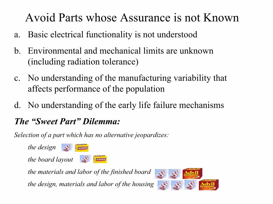
Avoid Parts whose Assurance is not Knowna. Basic electrical functionality is not understood
b. Environmental and mechanical limits are unknown (including radiation tolerance)
c. No understanding of the manufacturing variability that affects performance of the population
d. No understanding of the early life failure mechanisms
The “Sweet Part” Dilemma:Selection of a part which has no alternative jeopardizes:
the design
the board layout
the materials and labor of the finished board
the design, materials and labor of the housing
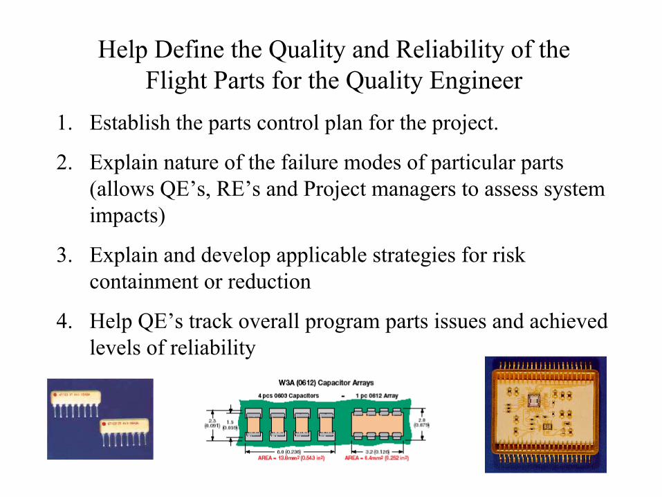
Help Define the Quality and Reliability of the Flight Parts for the Quality Engineer
1. Establish the parts control plan for the project.
2. Explain nature of the failure modes of particular parts (allows QE’s, RE’s and Project managers to assess system impacts)
3. Explain and develop applicable strategies for risk containment or reduction
4. Help QE’s track overall program parts issues and achieved levels of reliability
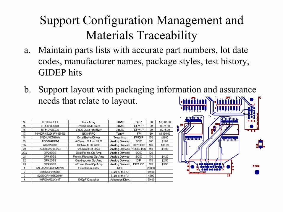
Support Configuration Management and Materials Traceability
a. Maintain parts lists with accurate part numbers, lot date codes, manufacturer names, package styles, test history, GIDEP hits
b. Support layout with packaging information and assurance needs that relate to layout.
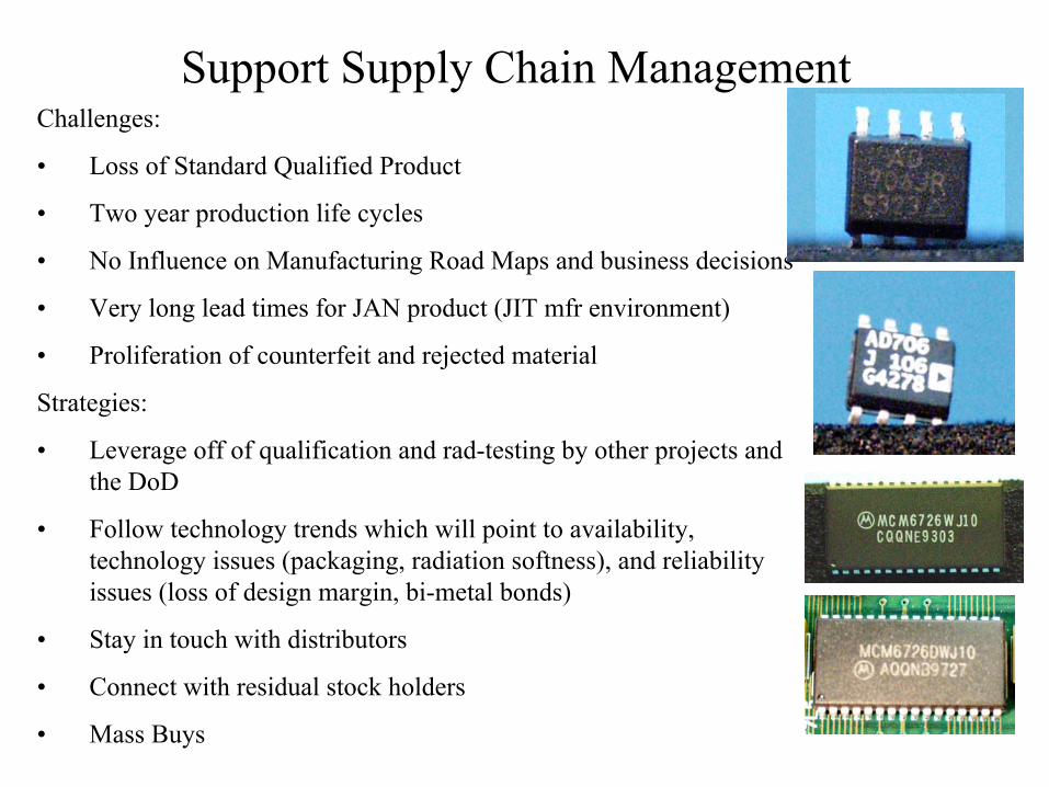
Support Supply Chain ManagementChallenges:
• Loss of Standard Qualified Product
• Two year production life cycles
• No Influence on Manufacturing Road Maps and business decisions
• Very long lead times for JAN product (JIT mfr environment)
• Proliferation of counterfeit and rejected material
Strategies:
• Leverage off of qualification and rad-testing by other projects and the DoD
• Follow technology trends which will point to availability, technology issues (packaging, radiation softness), and reliability issues (loss of design margin, bi-metal bonds)
• Stay in touch with distributors
• Connect with residual stock holders
• Mass Buys
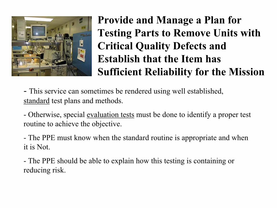
Provide and Manage a Plan for Testing Parts to Remove Units with Critical Quality Defects and Establish that the Item has Sufficient Reliability for the Mission
- This service can sometimes be rendered using well established, standard test plans and methods.
- Otherwise, special evaluation tests must be done to identify a proper test routine to achieve the objective.
- The PPE must know when the standard routine is appropriate and when it is Not.
- The PPE should be able to explain how this testing is containing or reducing risk.
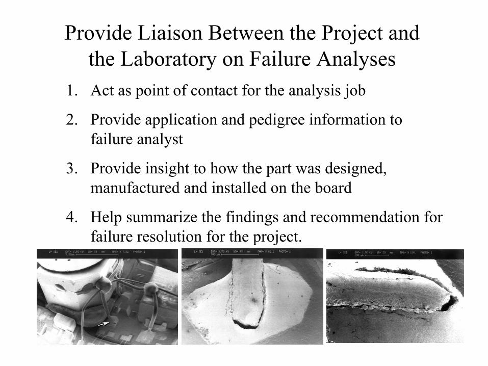
Provide Liaison Between the Project and the Laboratory on Failure Analyses
1. Act as point of contact for the analysis job
2. Provide application and pedigree information to failure analyst
3. Provide insight to how the part was designed, manufactured and installed on the board
4. Help summarize the findings and recommendation for failure resolution for the project.
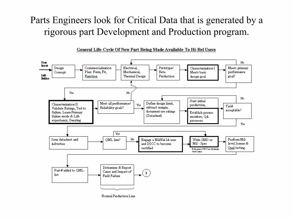
Parts Engineers look for Critical Data that is generated by a rigorous part Development and Production program.
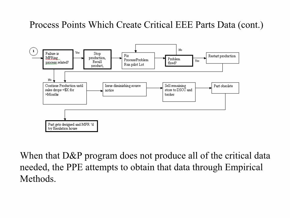
Process Points Which Create Critical EEE Parts Data (cont.)
When that D&P program does not produce all of the critical data needed, the PPE attempts to obtain that data through Empirical Methods.
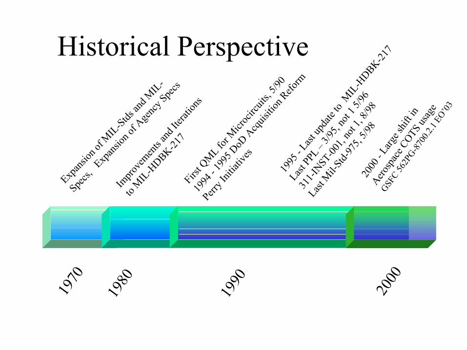
First Q
ML for M
icroc
ircuit
s, 5/90
1994
- 1995
DoD
Acq
uisitio
n Refo
rm
Perry I
nitiat
ives
1995
- Last up
date
to M
IL-H
DBK-217
Last PP
L –3/9
5, no
t 1 5/
96
311-I
NST-00
1, no
t 1, 8
/98
Last M
il-Std
-975,
5/98
1970
1980
1990 2000
Expan
sion o
f MIL
-Stds an
d MIL
-
Specs,
Exp
ansio
n of A
genc
y Spe
cs
Impro
vemen
ts an
d Iter
ation
s
to MIL
-HDBK-21
7
Historical Perspective
2000
-La
rge s
hift in
Aerosp
ace C
OTS us
age
GSFC 56
2PG-8
700.2
.1 EO
’03
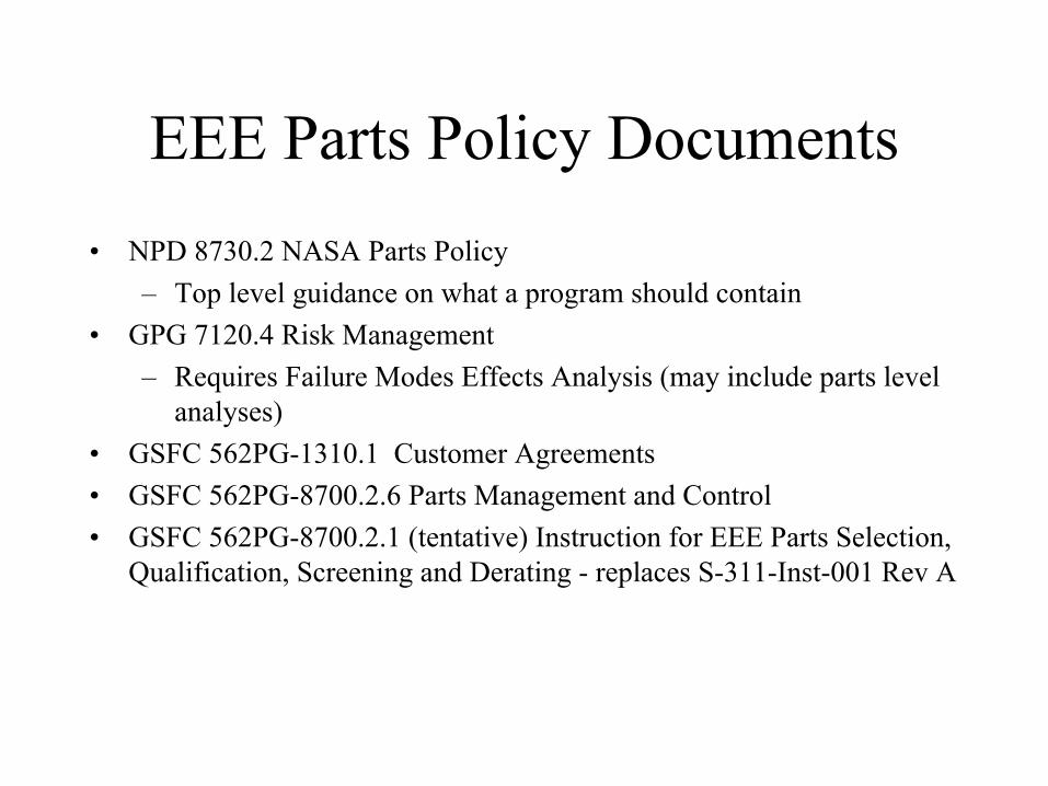
EEE Parts Policy Documents• NPD 8730.2 NASA Parts Policy
– Top level guidance on what a program should contain• GPG 7120.4 Risk Management
– Requires Failure Modes Effects Analysis (may include parts levelanalyses)
• GSFC 562PG-1310.1 Customer Agreements• GSFC 562PG-8700.2.6 Parts Management and Control• GSFC 562PG-8700.2.1 (tentative) Instruction for EEE Parts Selection,
Qualification, Screening and Derating - replaces S-311-Inst-001 Rev A
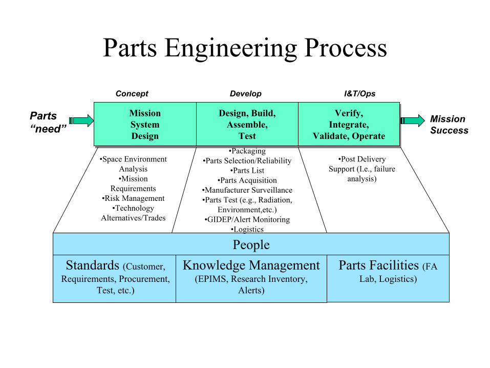
Parts Engineering Process
Mission Success
Parts “need”
MissionSystemDesign
MissionSystemDesign
Design, Build,Assemble,
Test
Design, Build,Assemble,
Test
Verify,Integrate,
Validate, Operate
Verify,Integrate,
Validate, Operate
Concept Develop I&T/Ops
Standards (Customer, Requirements, Procurement,
Test, etc.)
Knowledge Management (EPIMS, Research Inventory,
Alerts)
Parts Facilities (FA Lab, Logistics)
People
•Space Environment Analysis•Mission
Requirements•Risk Management
•Technology Alternatives/Trades
•Packaging •Parts Selection/Reliability
•Parts List•Parts Acquisition
•Manufacturer Surveillance•Parts Test (e.g., Radiation,
Environment,etc.)•GIDEP/Alert Monitoring
•Logistics
•Post Delivery Support (I.e., failure
analysis)
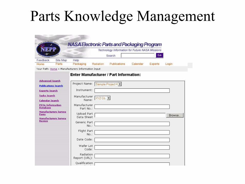
Parts Knowledge Management
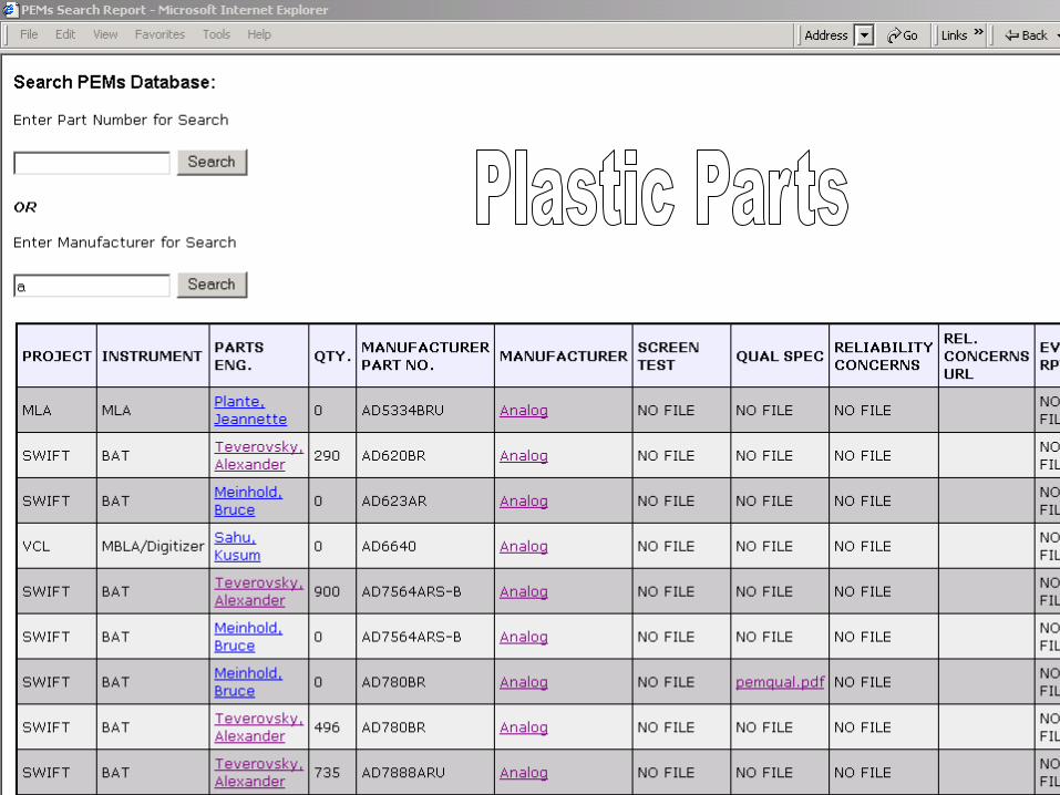
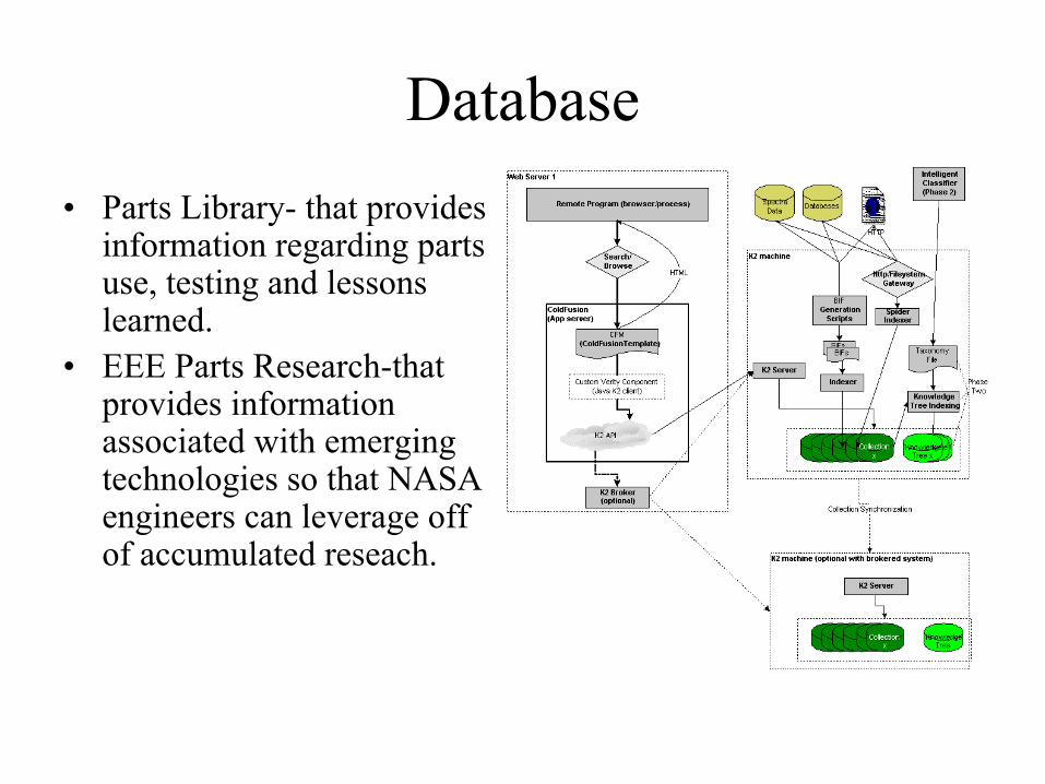
Database• Parts Library- that provides
information regarding parts use, testing and lessons learned.
• EEE Parts Research-that provides information associated with emerging technologies so that NASA engineers can leverage off of accumulated reseach.
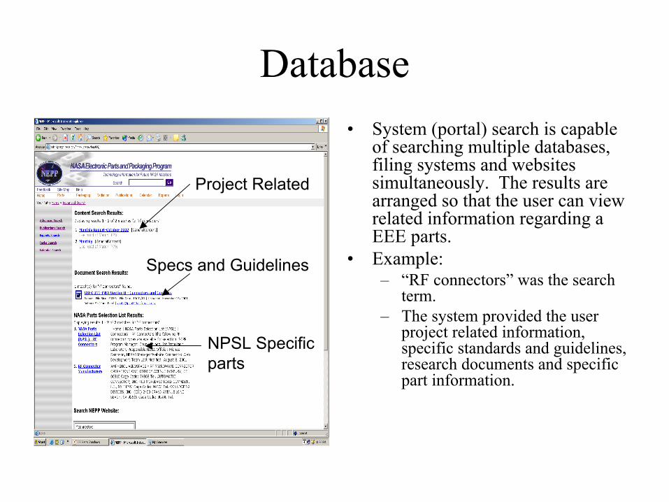
Database• System (portal) search is capable
of searching multiple databases, filing systems and websites simultaneously. The results are arranged so that the user can view related information regarding a EEE parts.
• Example:– “RF connectors” was the search
term.– The system provided the user
project related information, specific standards and guidelines, research documents and specific part information.
Project Related
Specs and Guidelines
NPSL Specific parts
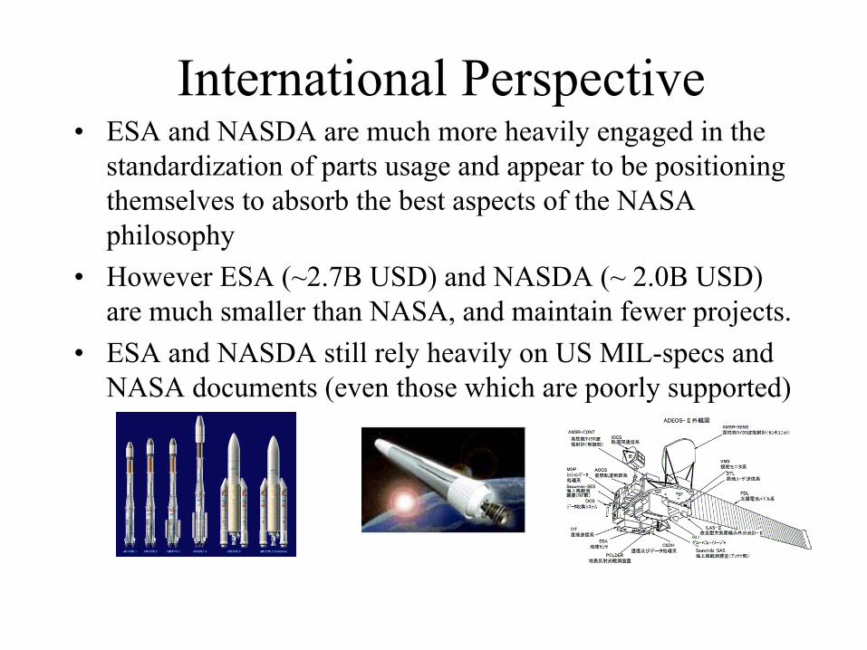
International Perspective• ESA and NASDA are much more heavily engaged in the
standardization of parts usage and appear to be positioning themselves to absorb the best aspects of the NASA philosophy
• However ESA (~2.7B USD) and NASDA (~ 2.0B USD) are much smaller than NASA, and maintain fewer projects.
• ESA and NASDA still rely heavily on US MIL-specs and NASA documents (even those which are poorly supported)
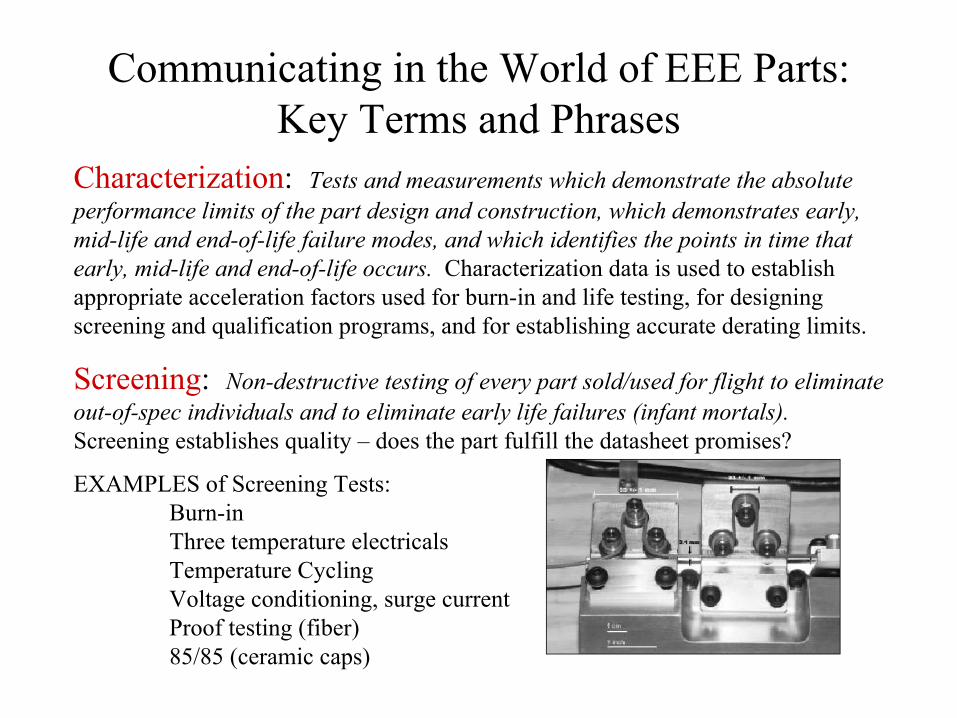
Communicating in the World of EEE Parts: Key Terms and Phrases
Characterization: Tests and measurements which demonstrate the absolute performance limits of the part design and construction, which demonstrates early, mid-life and end-of-life failure modes, and which identifies the points in time thatearly, mid-life and end-of-life occurs. Characterization data is used to establish appropriate acceleration factors used for burn-in and life testing, for designing screening and qualification programs, and for establishing accurate derating limits.
Screening: Non-destructive testing of every part sold/used for flight to eliminate out-of-spec individuals and to eliminate early life failures (infant mortals).Screening establishes quality – does the part fulfill the datasheet promises?
EXAMPLES of Screening Tests:Burn-inThree temperature electricalsTemperature CyclingVoltage conditioning, surge currentProof testing (fiber)85/85 (ceramic caps)
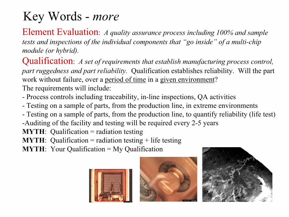
Key Words - moreElement Evaluation: A quality assurance process including 100% and sample tests and inspections of the individual components that “go inside” of a multi-chip module (or hybrid).Qualification: A set of requirements that establish manufacturing process control, part ruggedness and part reliability. Qualification establishes reliability. Will the part work without failure, over a period of time in a given environment? The requirements will include:- Process controls including traceability, in-line inspections, QA activities- Testing on a sample of parts, from the production line, in extreme environments- Testing on a sample of parts, from the production line, to quantify reliability (life test)-Auditing of the facility and testing will be required every 2-5 yearsMYTH: Qualification = radiation testingMYTH: Qualification = radiation testing + life testingMYTH: Your Qualification = My Qualification
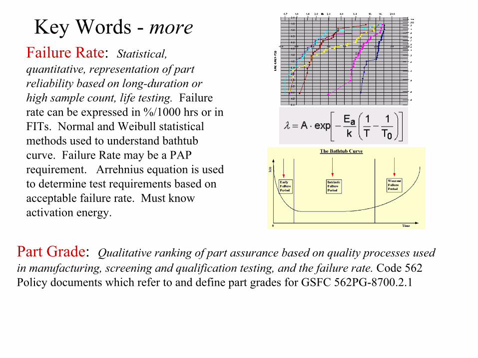
Key Words - moreFailure Rate: Statistical, quantitative, representation of part reliability based on long-duration or high sample count, life testing. Failure rate can be expressed in %/1000 hrs or in FITs. Normal and Weibull statistical methods used to understand bathtub curve. Failure Rate may be a PAP requirement. Arrehnius equation is used to determine test requirements based on acceptable failure rate. Must know activation energy.
Part Grade: Qualitative ranking of part assurance based on quality processes used in manufacturing, screening and qualification testing, and the failure rate. Code 562 Policy documents which refer to and define part grades for GSFC 562PG-8700.2.1
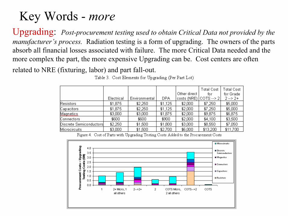
Key Words - moreUpgrading: Post-procurement testing used to obtain Critical Data not provided by the manufacturer’s process. Radiation testing is a form of upgrading. The owners of the parts absorb all financial losses associated with failure. The more Critical Data needed and the more complex the part, the more expensive Upgrading can be. Cost centers are often related to NRE (fixturing, labor) and part fall-out.
Military Parts: Class S/B, Q/V, H/K, /883, ER, QML, QPL: Parts controlled by military specifications. The specifications provide for all manner of performance and quality requirements. - Required testing is defined using standard test methods contained in documents such as MIL-STD-202 (passives), MIL-STD-883 and MIL-STD-750 (actives), MIL-STD-1344 (connectors).... - Successful compliance with the specification requirements including life testing, results in assignment of a part number that reflects a particular level of reliability (S, B, Q, V, H, K).- Different types of parts use different letters. These letters are not to be confused with the letters used to indicate failure rate level. - Special process controls and testing applies for space grade parts (“Class S”, V, K). - Specifications that require continuous life testing to establish and maintain a failure rate level are called Established Reliability (ER) specifications and are for passives.- Slash sheets are the documents used to explain the details of the performance requirements for a specific part number (and any exceptions to the requirements) including parameter values and tolerances (like a vendor’s datasheet). - QML certification is on a processing line basis, QPL is generally on a slash sheet basis.- Companies can be sued for marking their parts and knowingly not being certified to the mil-spec system or for knowingly not complying with the requirements of the specifications- The users of the parts control and maintain the specs and control manufacturer certification.- The DoD provides this system for anyone to use, free of charge. NASA augments it through participation in specification change reviews, certification audits, and engineering studies.
Key Words - more
Key Words - more
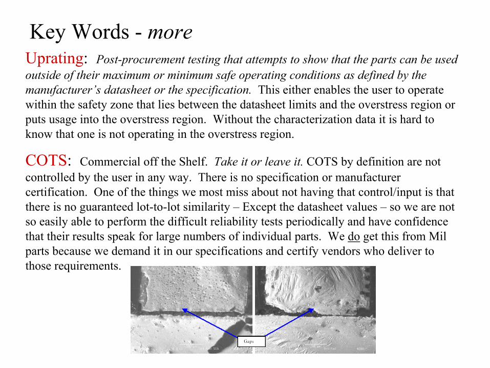
COTS: Commercial off the Shelf. Take it or leave it. COTS by definition are not controlled by the user in any way. There is no specification or manufacturer certification. One of the things we most miss about not having that control/input is that there is no guaranteed lot-to-lot similarity – Except the datasheet values – so we are not so easily able to perform the difficult reliability tests periodically and have confidence that their results speak for large numbers of individual parts. We do get this from Mil parts because we demand it in our specifications and certify vendors who deliver to those requirements.
Uprating: Post-procurement testing that attempts to show that the parts can be used outside of their maximum or minimum safe operating conditions as defined by the manufacturer’s datasheet or the specification. This either enables the user to operate within the safety zone that lies between the datasheet limits and the overstress region or puts usage into the overstress region. Without the characterization data it is hard to know that one is not operating in the overstress region.
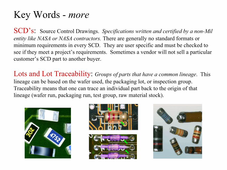
SCD’s: Source Control Drawings. Specifications written and certified by a non-Mil entity like NASA or NASA contractors. There are generally no standard formats or minimum requirements in every SCD. They are user specific and must be checked to see if they meet a project’s requirements. Sometimes a vendor will not sell a particular customer’s SCD part to another buyer.
Lots and Lot Traceability: Groups of parts that have a common lineage. This lineage can be based on the wafer used, the packaging lot, or inspection group.Traceability means that one can trace an individual part back to the origin of that lineage (wafer run, packaging run, test group, raw material stock).
Key Words - more
Key Words - moreHeritage: The engineering and use conditions experienced by a part from testing through use, which provides knowledge about how a part with the same or similar lineage will work under the same or similar conditions. The risk tolerance must be the same.Example 1: A part from a particular production process, was found to be tolerant of 10,000 thermal cycles between -55°C to +125°C. Another part from this production process (same geometries and materials) is expected to survive at least as well for 9,000 cycles in a -55°C to +85°C environment, based on heritage. A third part, from the same vendor and using a different package, cannot be assumed to be able to withstand these levels of thermal cycling based on heritage information.
Example 2: A part from a particular wafer run was packaged in 1999, thermal cycled and electrically tested at high, room and low temperatures (a.k.a. screening) to assure it would not be an early life failure in a high risk, low cost, secondary payload, flight experiment. Another part from the same wafer run, packaged three years later, for use in a primary payload, low risk, flight instrument, cannot use the first part’s heritage as a replacement for qualification testing.
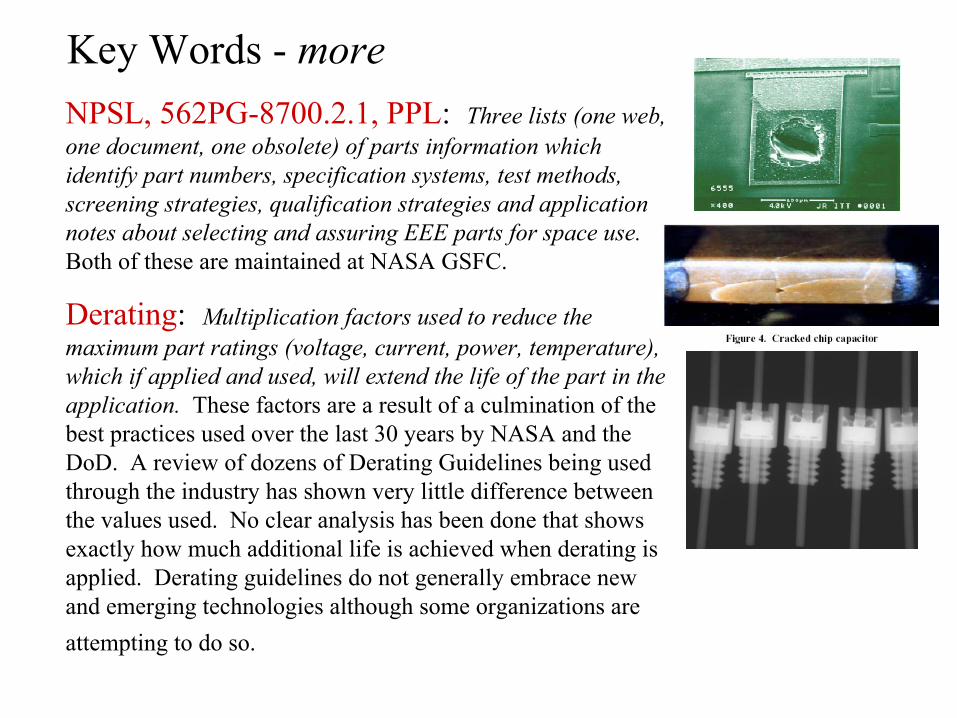
Key Words - moreNPSL, 562PG-8700.2.1, PPL: Three lists (one web, one document, one obsolete) of parts information which identify part numbers, specification systems, test methods, screening strategies, qualification strategies and application notes about selecting and assuring EEE parts for space use.Both of these are maintained at NASA GSFC.
Derating: Multiplication factors used to reduce the maximum part ratings (voltage, current, power, temperature), which if applied and used, will extend the life of the part in the application. These factors are a result of a culmination of the best practices used over the last 30 years by NASA and theDoD. A review of dozens of Derating Guidelines being used through the industry has shown very little difference between the values used. No clear analysis has been done that shows exactly how much additional life is achieved when derating is applied. Derating guidelines do not generally embrace new and emerging technologies although some organizations are attempting to do so.
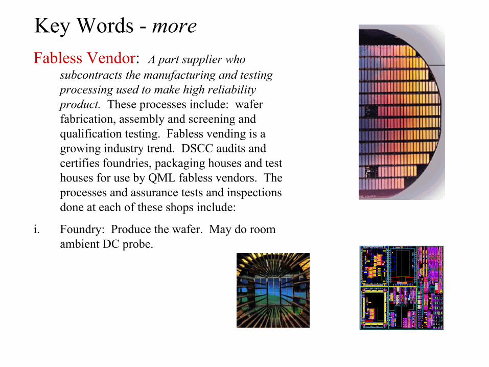
Key Words - moreFabless Vendor: A part supplier who
subcontracts the manufacturing and testing processing used to make high reliability product. These processes include: wafer fabrication, assembly and screening and qualification testing. Fabless vending is a growing industry trend. DSCC audits and certifies foundries, packaging houses and test houses for use by QML fabless vendors. The processes and assurance tests and inspections done at each of these shops include:
i. Foundry: Produce the wafer. May do room ambient DC probe.
Fabless Vendor cont.:
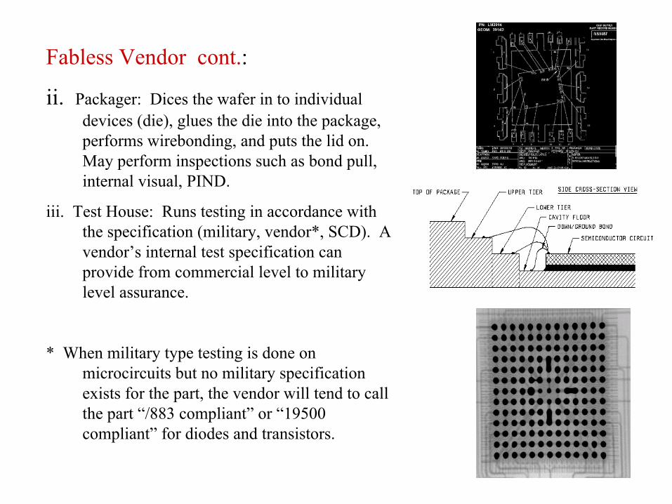
ii. Packager: Dices the wafer in to individual devices (die), glues the die into the package, performs wirebonding, and puts the lid on. May perform inspections such as bond pull, internal visual, PIND.
iii. Test House: Runs testing in accordance with the specification (military, vendor*, SCD). A vendor’s internal test specification can provide from commercial level to military level assurance.
* When military type testing is done on microcircuits but no military specification exists for the part, the vendor will tend to call the part “/883 compliant” or “19500 compliant” for diodes and transistors.
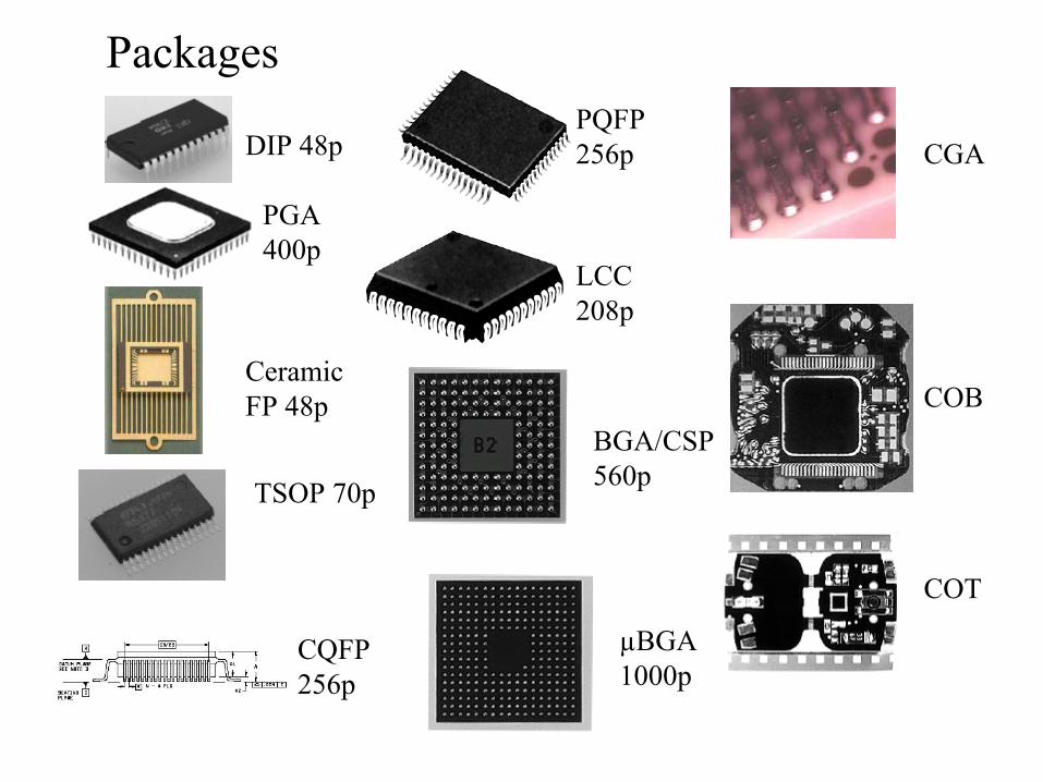
Packages
DIP 48p
PGA 400p
Ceramic FP 48p
TSOP 70p
CQFP 256p
PQFP 256p
LCC 208p
BGA/CSP 560p
µBGA 1000p
CGA
COT
COB
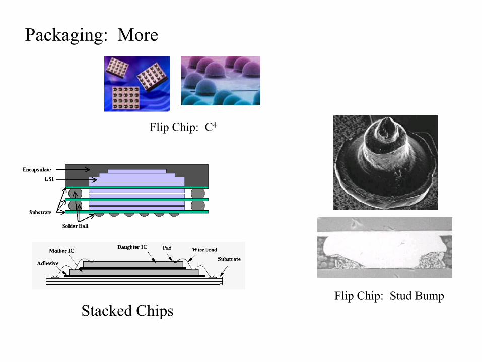
Flip Chip: Stud BumpStacked Chips
Flip Chip: C4
Packaging: More
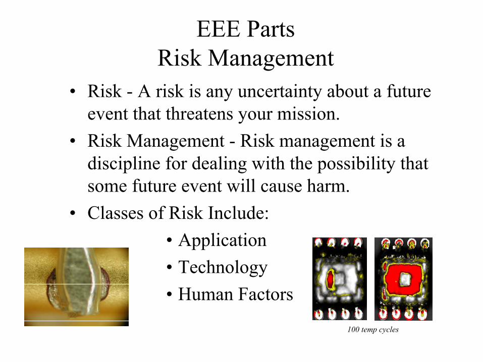
EEE Parts Risk Management
• Risk - A risk is any uncertainty about a future event that threatens your mission.
• Risk Management - Risk management is a discipline for dealing with the possibility that some future event will cause harm.
• Classes of Risk Include:• Application• Technology• Human Factors
100 temp cycles
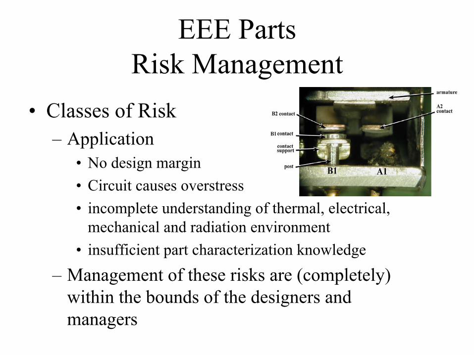
EEE Parts Risk Management
• Classes of Risk– Application
• No design margin• Circuit causes overstress• incomplete understanding of thermal, electrical,
mechanical and radiation environment• insufficient part characterization knowledge
– Management of these risks are (completely) within the bounds of the designers and managers
EEE Parts Risk Management
• Classes of Risk – Technology
• Unforeseen Obsolescence• Latent Defects • Design to cost• Proprietary barriers to information
– These risks are often start below the surface of information available to designers, managers, EEE parts engineers
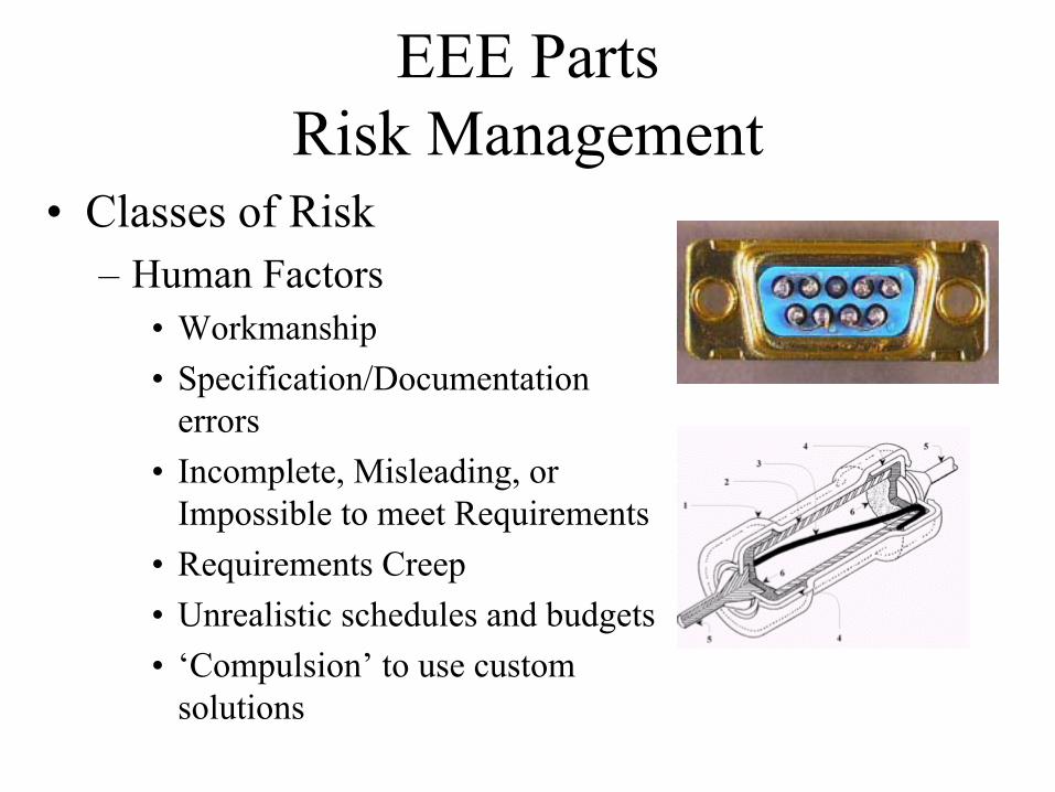
EEE Parts Risk Management
• Classes of Risk– Human Factors
• Workmanship• Specification/Documentation
errors• Incomplete, Misleading, or
Impossible to meet Requirements• Requirements Creep• Unrealistic schedules and budgets• ‘Compulsion’ to use custom
solutions
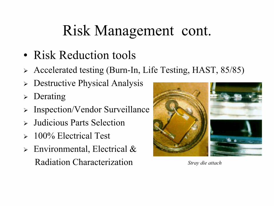
Risk Management cont.• Risk Reduction tools
Accelerated testing (Burn-In, Life Testing, HAST, 85/85)Destructive Physical AnalysisDeratingInspection/Vendor SurveillanceJudicious Parts Selection100% Electrical TestEnvironmental, Electrical & Radiation Characterization Stray die attach
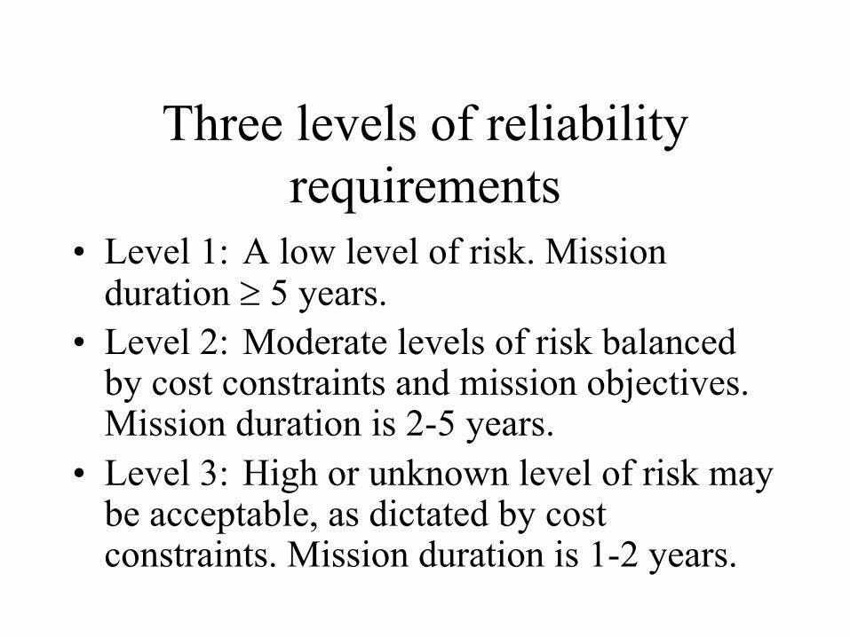
Three levels of reliability requirements
• Level 1: A low level of risk. Mission duration ≥ 5 years.
• Level 2: Moderate levels of risk balanced by cost constraints and mission objectives. Mission duration is 2-5 years.
• Level 3: High or unknown level of risk may be acceptable, as dictated by cost constraints. Mission duration is 1-2 years.
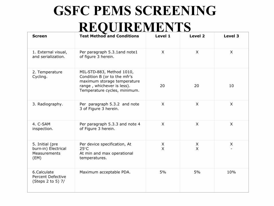
GSFC PEMS SCREENING REQUIREMENTS
Screen Test Method and Conditions Level 1 Level 2 Level 3
1. External visual, and serialization.
Per paragraph 5.3.1and note1 of figure 3 herein.
X X X
2. Temperature Cycling.
MIL-STD-883, Method 1010, Condition B (or to the mfr’s maximum storage temperature range , whichever is less). Temperature cycles, minimum.
20 20 10
3. Radiography. Per paragraph 5.3.2 and note 3 of Figure 3 herein.
X X X
4. C-SAM inspection.
Per paragraph 5.3.3 and note 4 of Figure 3 herein.
X X X
5. Initial (pre burn-in) Electrical Measurements (EM)
Per device specification, At 25°CAt min and max operational temperatures.
XX
XX
X-
6.Calculate Percent Defective (Steps 2 to 5) 7/
Maximum acceptable PDA. 5% 5% 10%
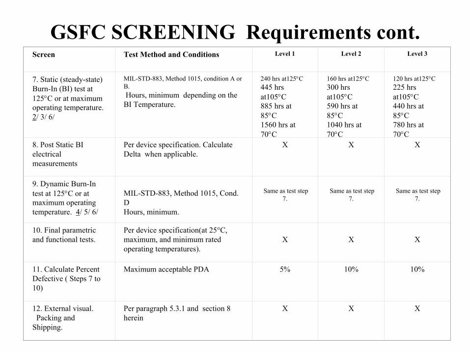
GSFC SCREENING Requirements cont.Screen Test Method and Conditions Level 1 Level 2 Level 3
7. Static (steady-state) Burn-In (BI) test at 125°C or at maximum operating temperature.2/ 3/ 6/
MIL-STD-883, Method 1015, condition A or B.Hours, minimum depending on the BI Temperature.
240 hrs at125°C 445 hrs at105°C885 hrs at 85°C1560 hrs at 70°C
160 hrs at125°C300 hrs at105°C590 hrs at 85°C1040 hrs at 70°C
120 hrs at125°C225 hrs at105°C440 hrs at 85°C780 hrs at 70°C
8. Post Static BI electrical measurements
Per device specification. Calculate Delta when applicable.
X X X
9. Dynamic Burn-In test at 125°C or at maximum operating temperature. 4/ 5/ 6/
MIL-STD-883, Method 1015, Cond. D Hours, minimum.
Same as test step 7.
Same as test step 7.
Same as test step 7.
10. Final parametric and functional tests.
Per device specification(at 25°C, maximum, and minimum rated operating temperatures).
X X X
11. Calculate Percent Defective ( Steps 7 to 10)
Maximum acceptable PDA 5% 10% 10%
12. External visual.Packing and
Shipping.
Per paragraph 5.3.1 and section 8 herein
X X X
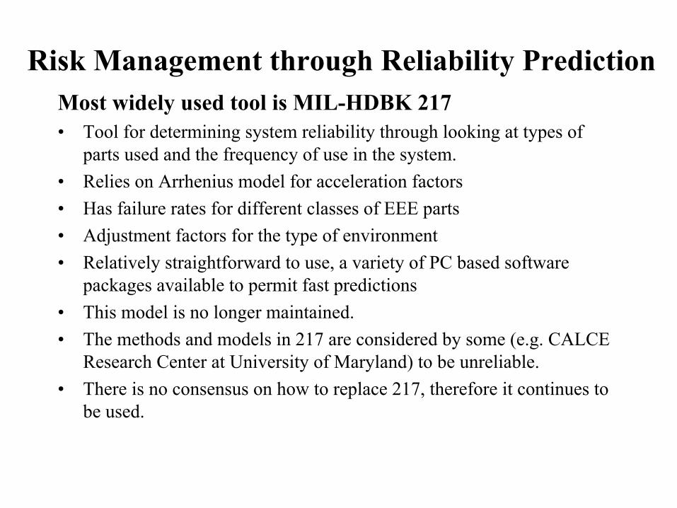
Risk Management through Reliability PredictionMost widely used tool is MIL-HDBK 217 • Tool for determining system reliability through looking at types of
parts used and the frequency of use in the system.• Relies on Arrhenius model for acceleration factors• Has failure rates for different classes of EEE parts• Adjustment factors for the type of environment• Relatively straightforward to use, a variety of PC based software
packages available to permit fast predictions• This model is no longer maintained.• The methods and models in 217 are considered by some (e.g. CALCE
Research Center at University of Maryland) to be unreliable.• There is no consensus on how to replace 217, therefore it continues to
be used.
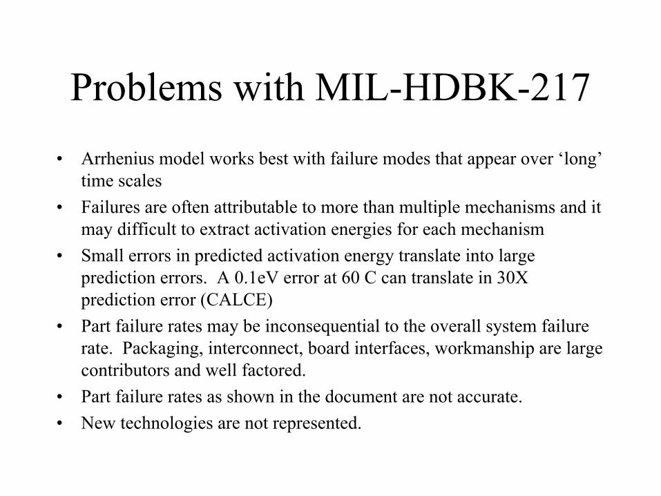
Problems with MIL-HDBK-217• Arrhenius model works best with failure modes that appear over ‘long’
time scales• Failures are often attributable to more than multiple mechanisms and it
may difficult to extract activation energies for each mechanism• Small errors in predicted activation energy translate into large
prediction errors. A 0.1eV error at 60 C can translate in 30X prediction error (CALCE)
• Part failure rates may be inconsequential to the overall system failure rate. Packaging, interconnect, board interfaces, workmanship are large contributors and well factored.
• Part failure rates as shown in the document are not accurate.• New technologies are not represented.
Alternatives to MIL-HDBK-217
• Alion Science & Technology (formerly IITRI Reliability Analysis Center in Rome, NY) has MIL-HDBK-217 replacement program called PRISM
• They claim that it overcomes the limitations of 217.• It covers EEE parts and mechanical parts and provides a
system level reliability assessment• It is backed up by a large parts reliability database.• http://rac.alionscience.com/prism/• Code 302 is the GSFC Systems Reliability Office and can
also be contacted about reliability matters.
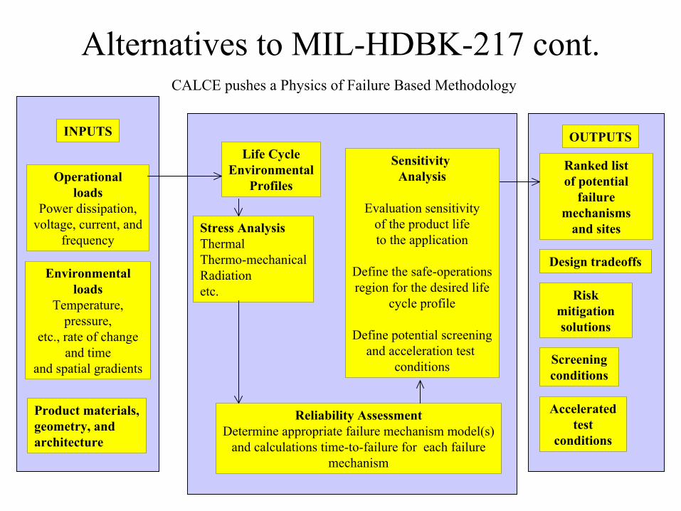
Alternatives to MIL-HDBK-217 cont.CALCE pushes a Physics of Failure Based Methodology
INPUTS
Operationalloads
Power dissipation,voltage, current, and
frequency
Environmentalloads
Temperature, pressure,
etc., rate of change and time
and spatial gradients
Product materials,geometry, and architecture
Life CycleEnvironmental
Profiles
Stress AnalysisThermalThermo-mechanicalRadiationetc.
Sensitivity Analysis
Evaluation sensitivityof the product lifeto the application
Define the safe-operationsregion for the desired life
cycle profile
Define potential screeningand acceleration test
conditions
Reliability AssessmentDetermine appropriate failure mechanism model(s)
and calculations time-to-failure for each failuremechanism
OUTPUTS
Ranked listof potential
failure mechanisms
and sites
Design tradeoffs
Risk mitigationsolutions
Screening conditions
Acceleratedtest
conditions
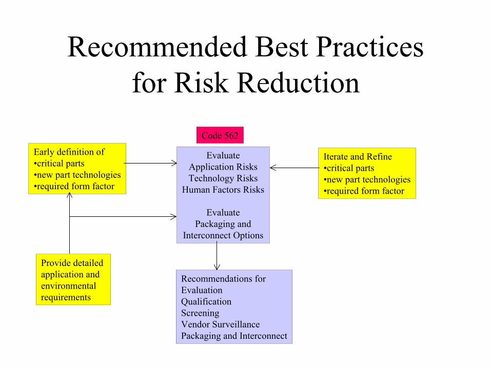
Recommended Best Practicesfor Risk Reduction
Early definition of•critical parts•new part technologies•required form factor
EvaluateApplication RisksTechnology Risks
Human Factors Risks
EvaluatePackaging and
Interconnect Options
Code 562
Provide detailed application and environmentalrequirements
Iterate and Refine•critical parts•new part technologies•required form factor
Recommendations forEvaluationQualificationScreeningVendor SurveillancePackaging and Interconnect
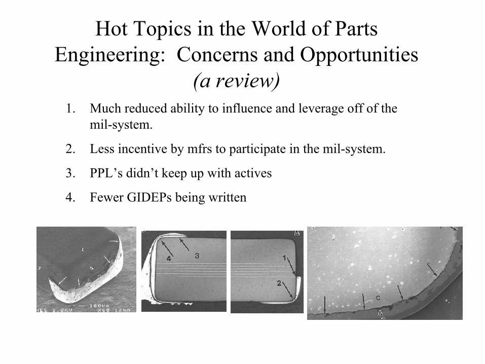
Hot Topics in the World of Parts Engineering: Concerns and Opportunities
(a review)1. Much reduced ability to influence and leverage off of the
mil-system.
2. Less incentive by mfrs to participate in the mil-system.
3. PPL’s didn’t keep up with actives
4. Fewer GIDEPs being written
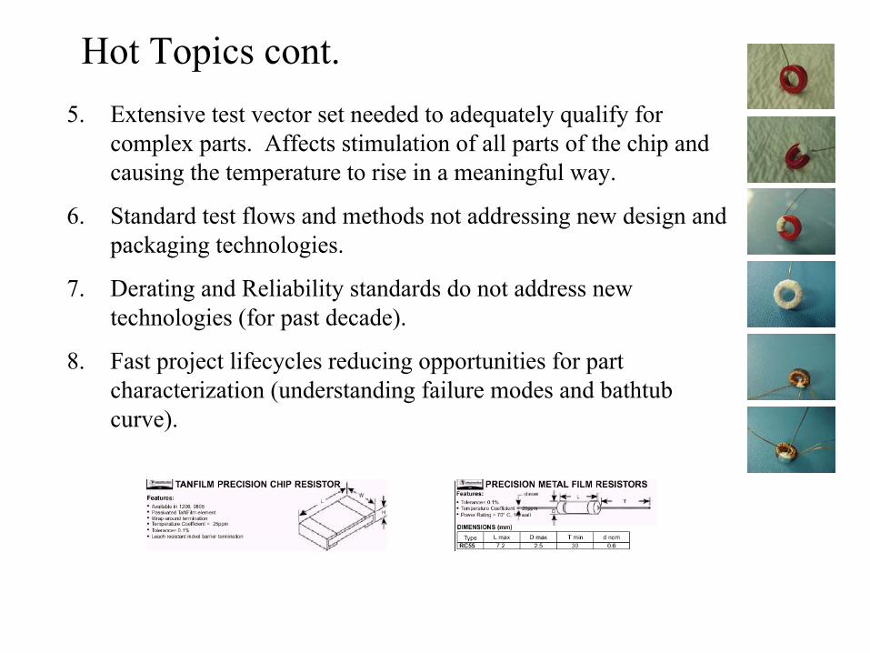
Hot Topics cont.5. Extensive test vector set needed to adequately qualify for
complex parts. Affects stimulation of all parts of the chip andcausing the temperature to rise in a meaningful way.
6. Standard test flows and methods not addressing new design and packaging technologies.
7. Derating and Reliability standards do not address new technologies (for past decade).
8. Fast project lifecycles reducing opportunities for part characterization (understanding failure modes and bathtub curve).
COTSi. New and emerging performance
ii. Not a good understand about the reliability as reported by the mfrs (variety of bases for FIT calculations and Ae).
iii. Reliability goals are 2 years. Margin between rating and overstress is going away.
iv. Cannot drive performance or assurance requirements. Essentially no warranty or liability by mfr.
v. Rapid product obsolescence
vi. Unknown lot homogeneity (w/in lot and lot-to-lot)
vii. Limited to No traceability
viii. Use of pure tin plating
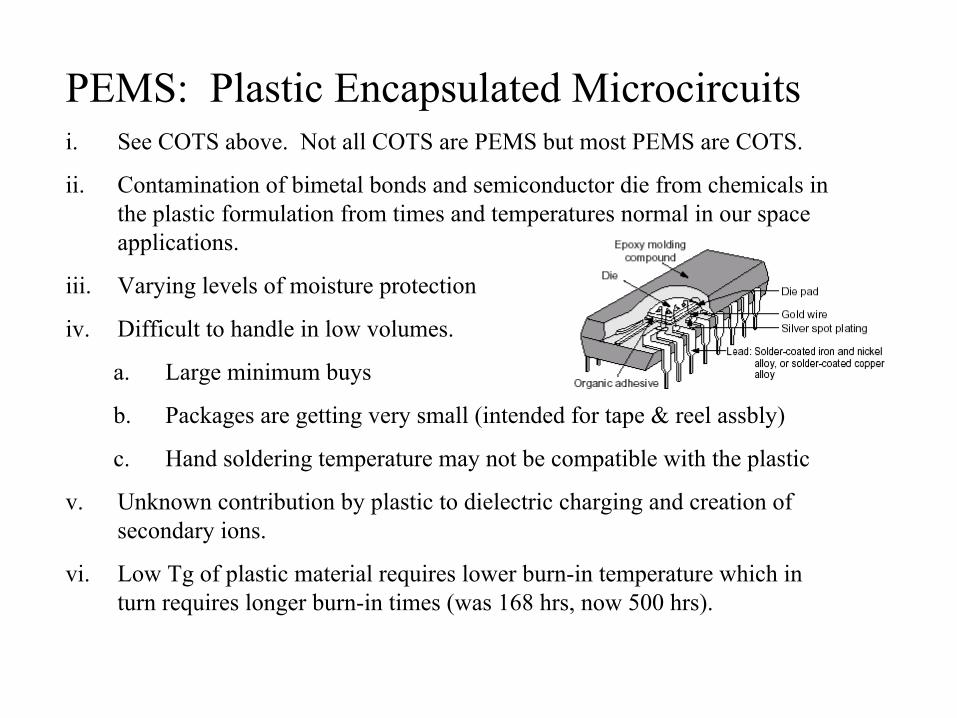
PEMS: Plastic Encapsulated Microcircuitsi. See COTS above. Not all COTS are PEMS but most PEMS are COTS.
ii. Contamination of bimetal bonds and semiconductor die from chemicals in the plastic formulation from times and temperatures normal in our space applications.
iii. Varying levels of moisture protection
iv. Difficult to handle in low volumes.
a. Large minimum buys
b. Packages are getting very small (intended for tape & reel assbly)
c. Hand soldering temperature may not be compatible with the plastic
v. Unknown contribution by plastic to dielectric charging and creation of secondary ions.
vi. Low Tg of plastic material requires lower burn-in temperature which in turn requires longer burn-in times (was 168 hrs, now 500 hrs).
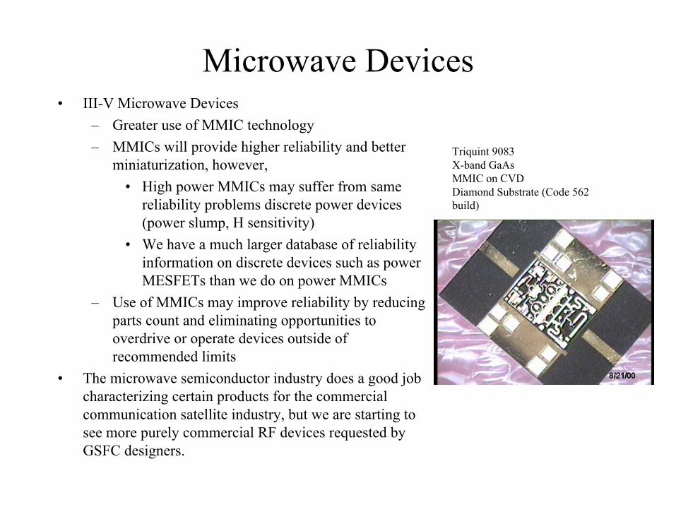
Microwave Devices• III-V Microwave Devices
– Greater use of MMIC technology– MMICs will provide higher reliability and better
miniaturization, however,• High power MMICs may suffer from same
reliability problems discrete power devices (power slump, H sensitivity)
• We have a much larger database of reliability information on discrete devices such as power MESFETs than we do on power MMICs
– Use of MMICs may improve reliability by reducing parts count and eliminating opportunities to overdrive or operate devices outside of recommended limits
• The microwave semiconductor industry does a good job characterizing certain products for the commercial communication satellite industry, but we are starting to see more purely commercial RF devices requested by GSFC designers.
Triquint 9083X-band GaAsMMIC on CVDDiamond Substrate (Code 562 build)

Microwave Devices
• Risk Management for III-V power applications– Ensure devices are well characterized for their
applications - reliability risk is greater for higher power devices
– Packaging, layout, bias conditions, gain compression, total voltage, multi-carrier operation. The reliability envelope is a multi-dimensional picture.
– RF Life Testing with margin is a very powerful risk avoidance tool.
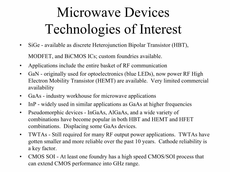
Microwave Devices Technologies of Interest
• SiGe - available as discrete Heterojunction Bipolar Transistor (HBT),
MODFET, and BiCMOS ICs; custom foundries available.• Applications include the entire basket of RF communication• GaN - originally used for optoelectronics (blue LEDs), now power RF High
Electron Mobility Transistor (HEMT) are available. Very limited commercial availability
• GaAs - industry workhouse for microwave applications• InP - widely used in similar applications as GaAs at higher frequencies• Pseudomorphic devices - InGaAs, AlGaAs, and a wide variety of
combinations have become popular in both HBT and HEMT and HFET combinations. Displacing some GaAs devices.
• TWTAs - Still required for many RF output power applications. TWTAs have gotten smaller and more reliable over the past 10 years. Cathode reliability is a key factor.
• CMOS SOI - At least one foundry has a high speed CMOS/SOI process that can extend CMOS performance into GHz range.
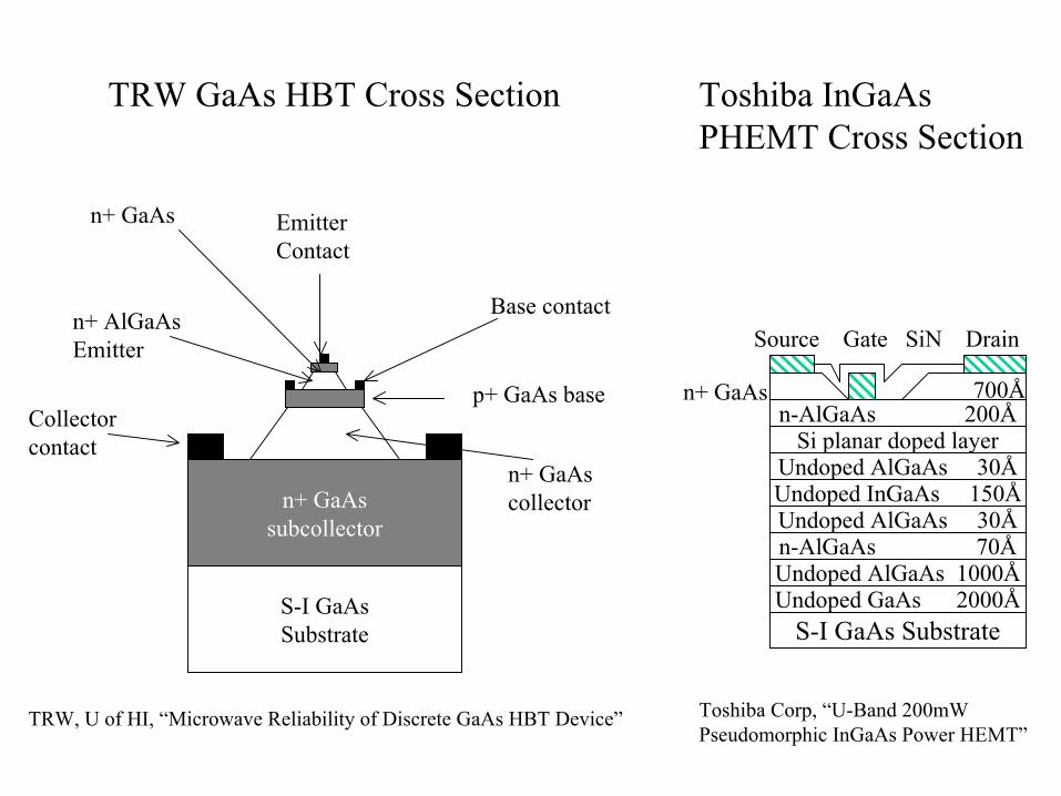
S-I GaAsSubstrate
n+ GaAssubcollector
n+ GaAscollector
Collectorcontact
p+ GaAs base
n+ AlGaAs Emitter
Base contact
n+ GaAs EmitterContact
TRW, U of HI, “Microwave Reliability of Discrete GaAs HBT Device”
TRW GaAs HBT Cross Section
S-I GaAs SubstrateUndoped GaAs 2000ÅUndoped AlGaAs 1000Ån-AlGaAs 70ÅUndoped AlGaAs 30ÅUndoped InGaAs 150ÅUndoped AlGaAs 30Å
Si planar doped layern-AlGaAs 200Å
n+ GaAs 700Å
Source Gate SiN Drain
Toshiba InGaAsPHEMT Cross Section
Toshiba Corp, “U-Band 200mWPseudomorphic InGaAs Power HEMT”
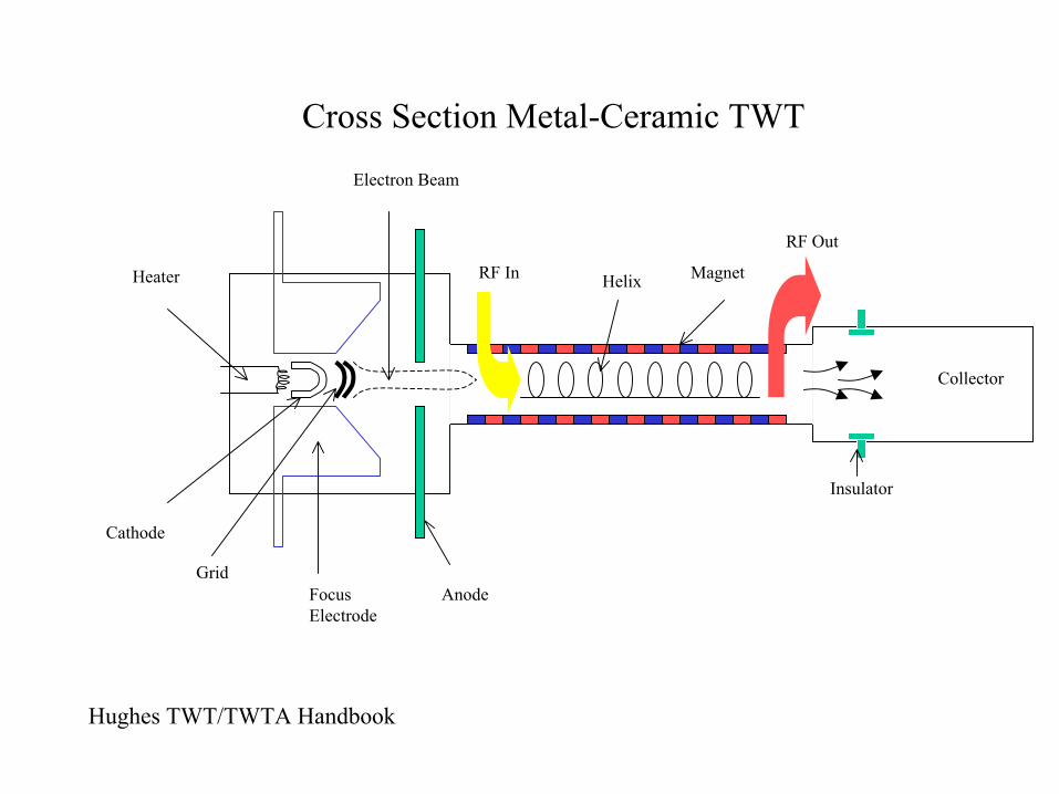
Cross Section Metal-Ceramic TWT
Heater
FocusElectrode
Cathode
Grid
Electron Beam
Anode
RF In Helix Magnet
RF Out
Collector
Insulator
Hughes TWT/TWTA Handbook
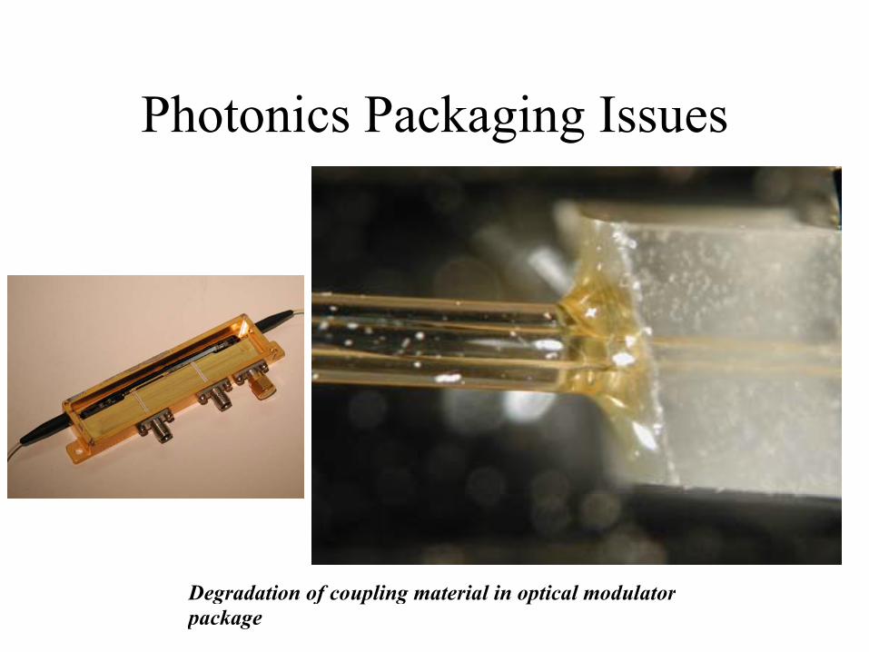
Degradation of coupling material in optical modulatorpackage
Photonics Packaging Issues
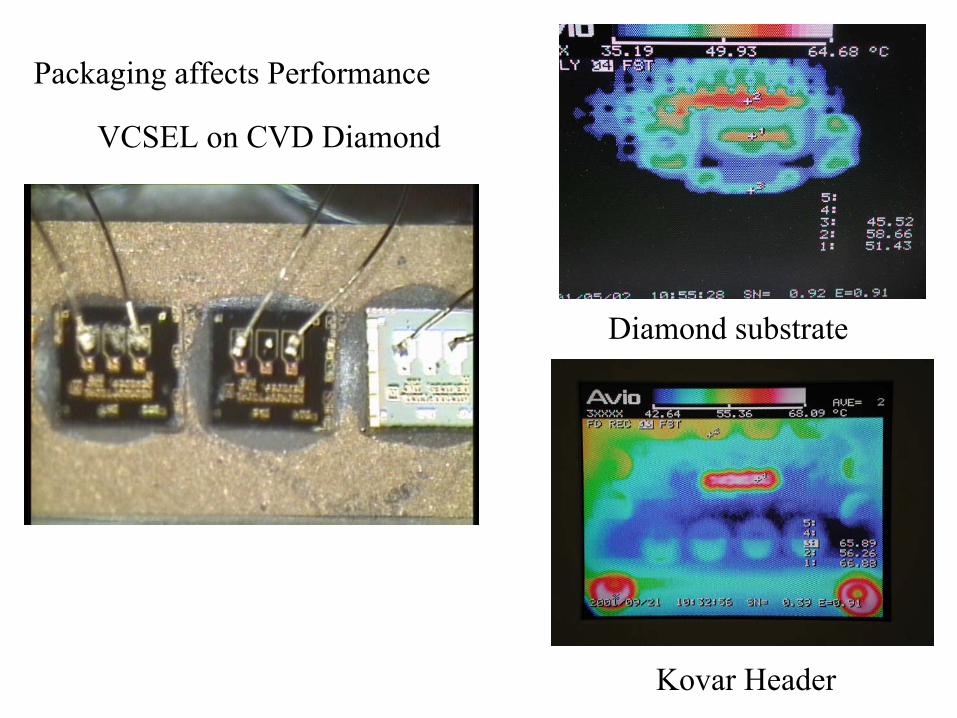
VCSEL on CVD Diamond
Diamond substrate
Kovar Header
Packaging affects Performance
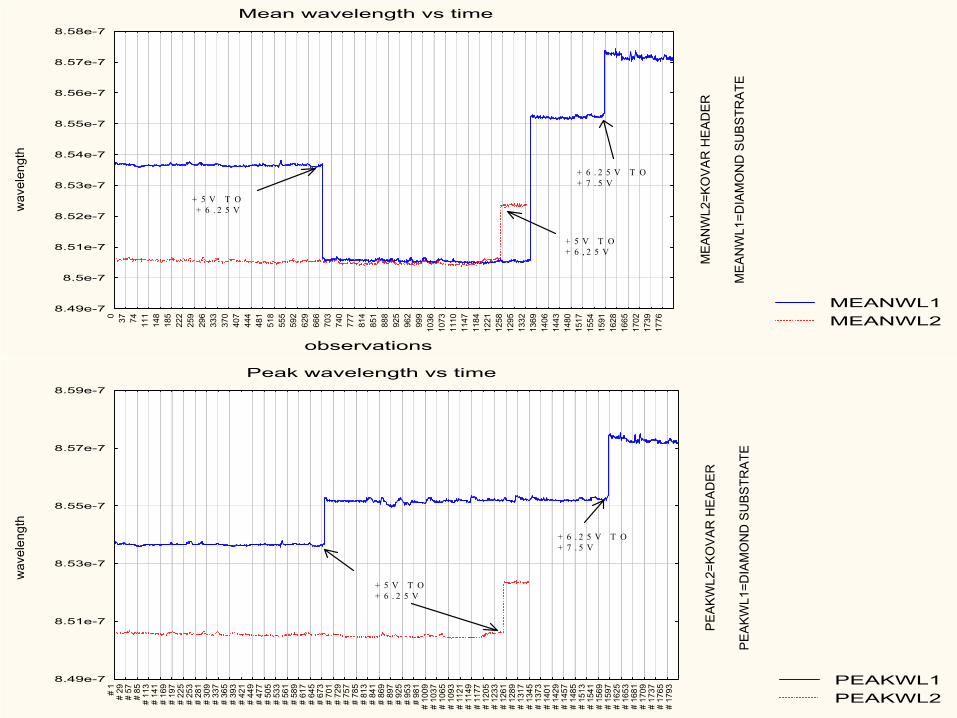
MEANWL1MEANWL2
Mean wavelength vs time
observations
wav
elen
gth
MEA
NW
L1=D
IAM
ON
D S
UBS
TRAT
E
MEA
NW
L2=K
OVA
R H
EAD
ER
8.49e-7
8.5e-7
8.51e-7
8.52e-7
8.53e-7
8.54e-7
8.55e-7
8.56e-7
8.57e-7
8.58e-7
0 37 74 111
148
185
222
259
296
333
370
407
444
481
518
555
592
629
666
703
740
777
814
851
888
925
962
999
1036
1073
1110
1147
1184
1221
1258
1295
1332
1369
1406
1443
1480
1517
1554
1591
1628
1665
1702
1739
1776
+ 5 V T O + 6 . 2 5 V
+ 6 . 2 5 V T O+ 7 . 5 V
+ 5 V T O + 6 , 2 5 V
PEAKWL1PEAKWL2
Peak wavelength vs time
wav
elen
gth
PEAK
WL1
=DIA
MO
ND
SU
BSTR
ATE
PEAK
WL2
=KO
VAR
HEA
DER
8.49e-7
8.51e-7
8.53e-7
8.55e-7
8.57e-7
8.59e-7
# 1
# 29
# 57
# 85
# 11
3#
141
# 16
9#
197
# 22
5#
253
# 28
1#
309
# 33
7#
365
# 39
3#
421
# 44
9#
477
# 50
5#
533
# 56
1#
589
# 61
7#
645
# 67
3#
701
# 72
9#
757
# 78
5#
813
# 84
1#
869
# 89
7#
925
# 95
3#
981
# 10
09#
1037
# 10
65#
1093
# 11
21#
1149
# 11
77#
1205
# 12
33#
1261
# 12
89#
1317
# 13
45#
1373
# 14
01#
1429
# 14
57#
1485
# 15
13#
1541
# 15
69#
1597
# 16
25#
1653
# 16
81#
1709
# 17
37#
1765
# 17
93
+ 5 V T O+ 6 . 2 5 V
+ 6 . 2 5 V T O+ 7 . 5 V
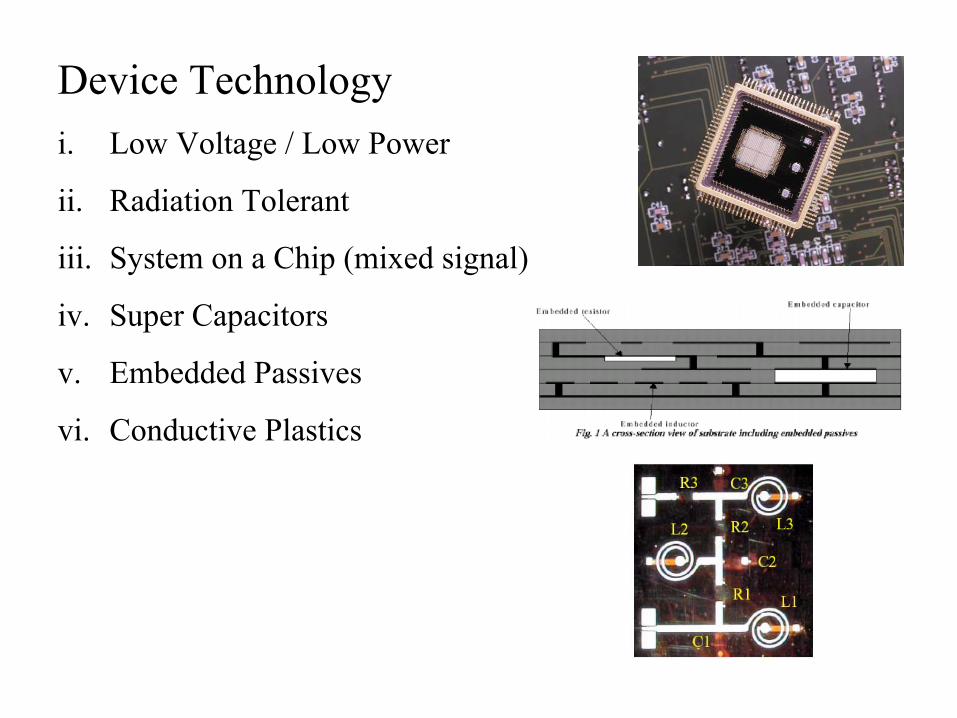
Device Technologyi. Low Voltage / Low Power
ii. Radiation Tolerant
iii. System on a Chip (mixed signal)
iv. Super Capacitors
v. Embedded Passives
vi. Conductive Plastics
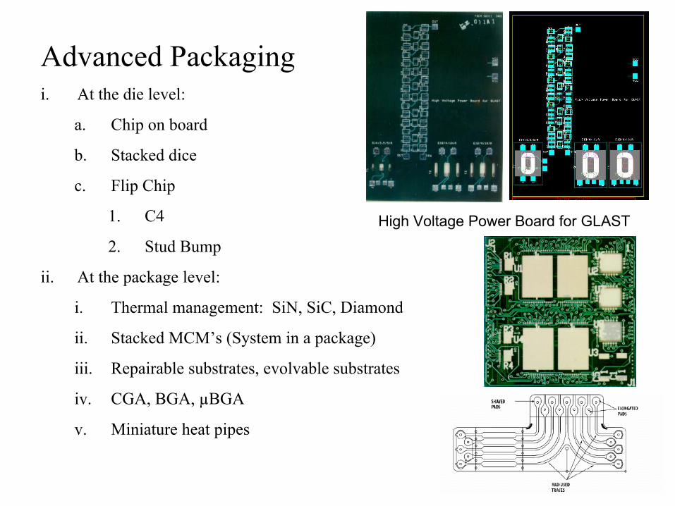
Advanced Packagingi. At the die level:
a. Chip on board
b. Stacked dice
c. Flip Chip
1. C4
2. Stud Bump
ii. At the package level:
i. Thermal management: SiN, SiC, Diamond
ii. Stacked MCM’s (System in a package)
iii. Repairable substrates, evolvable substrates
iv. CGA, BGA, µBGA
v. Miniature heat pipes
High Voltage Power Board for GLAST
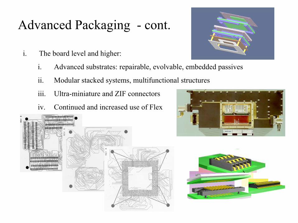
i. The board level and higher:
i. Advanced substrates: repairable, evolvable, embedded passives
ii. Modular stacked systems, multifunctional structures
iii. Ultra-miniature and ZIF connectors
iv. Continued and increased use of Flex
Advanced Packaging - cont.
Summary
Parts Engineers have special knowledge that can help projects avoid known problems and resolve newly found ones.
Parts Engineering is based on a tradition which uses characterization, screening, qualification and process control methods for reducing risk to NASA projects.
New technologies, the dominance of COTS, and ultra-fast project and product life-cycle times are reducing our ability to accomplish adequate part characterization, making it more challenging to design and implement appropriate test programs.
Electronic part and packaging production continues to exist in a period of technology expansion which will continue to put pressure on traditional parts engineering methods.
Through leveraging (testing and strategic buying), NASA projects can build the knowledge base about new technologies, making risk reduction techniques more effective.
Contact Information for Code 562Civil Servant:
Harry Shaw, 301-286-6616, [email protected] Sharma, 301 286-6165, [email protected] Sahu, 301 286-8838, [email protected] Patel, 301 286-9267, [email protected]
Contractor:
Jeannette Plante, Dynamic Range Corp.301-286-7437, [email protected], [email protected]
Patti Hart, QSS301-286-3845, [email protected]
Space Radiation Environment and Effects: Overview for
Electronics DesignersKenneth A. LaBel
NASA/[email protected]
Code 561.4 Group LeaderProject Manager, Electronics Radiation Characterization Project
Chief Technologist, Living With a Star Space Environment Testbed
Radiation and Systems Engineering: A Rational Approach for Space Systems
• Define the Environment– External to the spacecraft
• Evaluate the Environment– Internal to the spacecraft
• Define the Requirements– Define criticality factors
• Evaluate Design/Components– Existing data/Testing/Performance characteristics
• “Engineer” with Designers– Parts replacement/Mitigation schemes
• Iterate Process– Review parts list based on updated knowledge
Define the Hazard• The radiation environment external to the spacecraft
– Trapped particles• Protons• Electrons
– Galactic cosmic rays (heavy ions)– Solar particles (protons and heavy ions)
• Based on– Time of launch and mission duration– Orbital parameters, …
• Provides– Nominal and worst-case trapped particle fluxes– Peak “operate-through” fluxes (solar or trapped)– Dose-depth curve of total ionizing dose (TID)
Note: We are currently using static models for a dynamic environment
Evaluate the Hazard• Utilize mission-specific geometry to determine particle fluxes
and TID at locations inside the spacecraft– 3-D ray trace (geometric sectoring)
• Typically multiple steps– Basic geometry (empty boxes,…) or single electronics box– Detailed geometry
• Include printed circuit boards (PCBs), cables, integrated circuits (ICs), thermal louvers, etc…
• Usually an iterative process– Initial spacecraft design– As spacecraft design changes– Mitigation by changing box location
Define Requirements• Environment usually based on hazard definition with “nominal shielding” or
basic geometry– Using actual spacecraft geometry sometimes provides a “less harsh” radiation
requirement• Performance requirements for “nominal shielding” such as 70 mils of Al or
actual spacecraft configuration– TID– DDD (protons, neutrons)– SEE
• Specification is more complex• Often requires SEE criticality analysis (SEECA) method be invoked
• Must include radiation design margin (RDM)– At least a factor of 2– Often required to be higher due to device issues and environment uncertainties
System Requirements -SEE Specifications
• For TID, parts can be given A number (with margin)– SEE is much more application specific
• SEE is unlike TID– Probabilistic events, not long-term
• Equal probabilities for 1st day of mission or last day of mission
– Maybe by definition!
Radiation Design Margins (RDMs) - 1 of 2
• How much risk does the project want to take?• Uncertainties that must be considered
– Dynamics of the environment– Test data
• Applicability of test data– Does the test data reflect how the device is used in THIS design?
• Device variances– Lot-to-lot, wafer-to-wafer, device-to-device
Radiation Design Margins (RDMs) - 2 of 2
• Is factor of 2 enough?– For some issues such as ELDRs, no.
• Is factor of 5 too high?– It depends
• Risk trade– Weigh RDM vs. cost/performance vs.
probability of issue vs. system reliability etc…
Evaluate Design/Component Usage
• Screen parts list– Use existing databases
• RADATA, REDEX, Radhome, IEEE TNS, IEEE Data Workshop Records, Proceedings of RADECS, etc.
• Evaluate test data– Look for processes or products with known radiation tolerance (beware
of SEE and displacement damage!)• BAE Systems, Honeywell Solid State Electronics, UTMC, Harris, etc.
• Radiation test unknowns or non-RH guaranteed devices• Provide performance characteristics
– Usually requires application specific information: understand the designer’s sensitive parameters
• SEE rates• TID/DDD
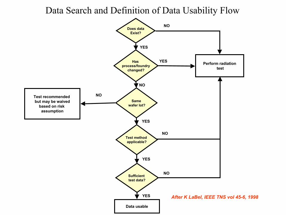
Does dataExist?
Samewafer lot?
Sufficient test data?
Test method applicable?
Has process/foundry
changed?
Perform radiationtest
NO
YES
NO
Test recommended but may be waived
based on risk assumption
NO
NO
NO
YES
YES
Data usable
YES
YES
After K LaBel, IEEE TNS vol 45-6, 1998
Data Search and Definition of Data Usability Flow
System Radiation Test Requirements
• All devices with unknown characteristics should be ground radiation tested (TID and SEE)
• All testing should be performed on flight lot, if possible
• Testing should mimic or bound the flight usage, if possible
Test Requirements - TID
• All non-RH electronic/optic devices should be lot tested– Typically utilize STANDARD test methods as outlined in
MIL 1019.5• Includes options for low dose rate testing and ELDRS
– ELDRS method does not necessarily bound the results• What do we do about mixed signal devices like BiCMOS processes?
– Test levels should exceed requirement (with RDM)• Dose rate issues and annealing issues should be minimized• Units: Dose in krads (material)
Test Requirements - SEE• All non-SEE (not just RH) hardened devices should be
lot tested– Several manufacturers market radiation-hardened FPGAs.
• Quiz: Are the devices really radiation-hard?• Hint: We use “radiation-hardened” FPGAs as particle detectors for
test trips. :-)
• Determine if heavy ion, proton, or both types of test are needed– Sample size– Particle energy– Fluence