Embed Size (px)
Citation preview
Vol.:(0123456789)
SN Applied Sciences (2019) 1:1503 | https://doi.org/10.1007/s42452-019-1550-9
Research Article
Effect of baffles shape on the flow patterns and power consumption in stirred vessels
Mohammed Foukrach1 · Houari Ameur2
Received: 19 June 2019 / Accepted: 22 October 2019 / Published online: 28 October 2019 © Springer Nature Switzerland AG 2019
AbstractEffects of the baffles shape on the fluid velocities, flow patterns and power consumption in vessels agitated by a six blade Rushton turbine are explored in this paper. The curvature of baffles, their length, position and width are the main parameters under investigation. The study is carried out by using the Computational Fluid Dynamics tool, for a range of Reynolds number in the turbulent flow regime from 104 to 105. The comparison between the straight and curved baffles revealed that the curved shape allows wider well stirred region and more powerful radial jet of fluid than the straight baffle. In addition, the increase in baffle curvature allows a reduction in power consumption. When partial baffles are inserted in the vessel, the lowest value of power number is obtained with baffles located at the upper part of vessel, fol‑lowed by those located at the center and then at the lower part. Concerning the effect of baffle length, the baffles with partial length which are located at the center position in vessel require the lowest power consumption.
Keywords Stirred system · Shape of baffles · Curved baffles · Baffle position · Turbulent flows
List of symbolsa Blade width, mb Blade height, mc Distance between agitator and tank bot‑
tom, mC1, C2, ρk, ρε Empirical constants, –D Inner diameter of the agitated vessel, md Turbine diameter, mdd Disc diameter, mdsh Shaft diameter, mGk Generation term, –h Baffle height, mhv Height of the recirculation loop generated
in the upper part of the tank, mH Liquid height in the vessel, mk Turbulence kinetic energy, JL Baffle length, mN Agitator speed, s−1
Np Power number, –P Power consumption, W
Qv Viscous dissipation function, 1/sR Radial coordinate, mr Baffle curvature radius, mRe Reynolds number, –Ui ith component of the fluid velocity, m/sV Velocity, m/sVr Radial velocity, m/sVz Axial velocity, m/sVθ Tangential velocity, m/sVtip Velocity at the impeller tip, m/sW Baffle width, mxi One of the three coordinate directions, m
Greek lettersθ Angular coordinate, degreeω Angular velocity, rad/sε Dissipation rate of turbulence, m2/s3
ρ Fluid density, kg/m3
μt Turbulent viscosity, Pa sη Viscosity, Pa s
* Houari Ameur, [email protected]; ameur@cuniv‑naama.dz | 1Faculty of Mechanical Engineering, USTO‑MB, 1505 El M’naouar, Oran, Algeria. 2Department of Technology, University Centre of Naama (Ctr Univ Naama), Po. Box 66, 45000 Naama, Algeria.
Vol:.(1234567890)
Research Article SN Applied Sciences (2019) 1:1503 | https://doi.org/10.1007/s42452-019-1550-9
1 Introduction
The agitation of liquids in cylindrical tanks is an opera‑tion at least simple to realize, but always complex to characterize, because of the nature of flows and geom‑etry of the system. Today, the majority of the operations of agitation and mixture are carried out by means of an impeller turning around a shaft, placed in a tank, gener‑ally of a cylindrical form. In stirred tanks, the hydrody‑namics induced are mainly dependent upon the impeller design and interaction of flow with tank internals [1–4]. Several works have been achieved by numerical simu‑lations on the turbulent flows induced by the Rushton turbine [5–7]. Among other papers, Montante et al. [8] conducted a simulation of the effect of varying impeller clearances from the tank bottom on the hydrodynam‑ics and power consumption for the Rushton turbine. Several studies on the characterization of flows induced by different impellers can be found in the literature [9]. However, the Rushton turbine remains used in different industrial processes, due to its manufacturing simplic‑ity and cleaning easiness. In addition, it was taken as a reference case in recent research studies to find more efficient mixing systems. Ameur et al. [10] have charac‑terized the hydrodynamics and power consumption for different radial impellers, including a six‑blade Rushton turbine, a radial turbine with six flat blades and a disc impeller. Other authors investigated the turbulent flow generated by a radial turbine: Beloudane et al. [11] for turbines with hollow blades, Foukrach et al. [12] for dif‑ferent vessel shapes, Youcefi et al. [5] for different sloths on the vessel walls.
The power consumption is a key role to determine the efficiency of stirred tanks and the choice of impellers is mainly based on this criterion [13]. The baffles called also against‑blades, these elements fixed at the level of the tank wall are used to avoid the formation of the vortex, induced by the centrifugal force due to the rotation of the agitator and essential to obtain an effective mixture in mode of turbulent flow. The main objective of baffle insert in stirred tanks is to avoid the swirling flows, to reduce the viscous dissipation by the impeller, to cre‑ate and promote the stability of power requirements and thus enhancing mixing. Some studies have been achieved on the effect of baffle design, including those of Bittins and Zehner [14], Karcz and Major [15], Ammar et al. [16] and Kamla et al. [17] for different impellers [a propeller, a pitched blade turbine (PBT) and a Rushton turbine (RT)]. The influence of some geometrical param‑eters of baffles (length, width, number and the clearance between the tank bottom and the lower edge of baffles) has been the subject of some studies [18–21].
Even many research studies have been performed regarding the effect of baffles in stirred tanks; the curva‑ture shape of baffles remains another issue that has not been studied previously, as stated in the literature review. Therefore, the main objective of the present work is to explore the effect of baffle curvature on the hydrodynam‑ics and power consumption in a cylindrical tank equipped with a Rushton turbine. We focus on the effects of the shape of baffles, their length, position and width.
2 Description of the stirred system
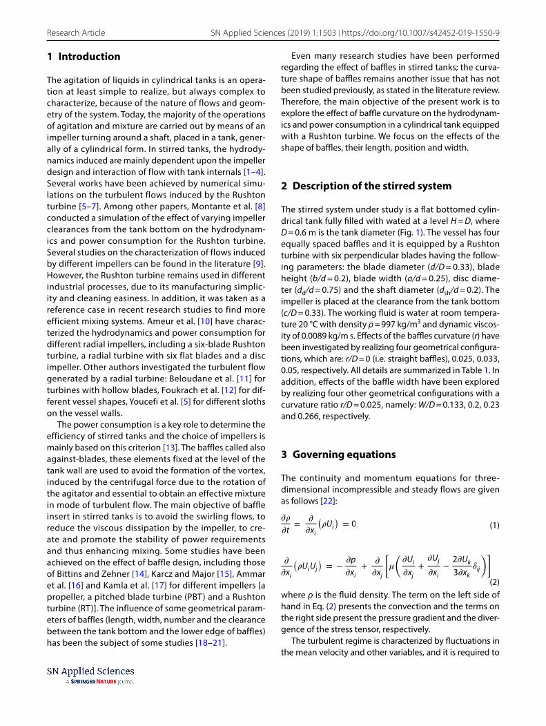
The stirred system under study is a flat bottomed cylin‑drical tank fully filled with wated at a level H = D, where D = 0.6 m is the tank diameter (Fig. 1). The vessel has four equally spaced baffles and it is equipped by a Rushton turbine with six perpendicular blades having the follow‑ing parameters: the blade diameter (d/D = 0.33), blade height (b/d = 0.2), blade width (a/d = 0.25), disc diame‑ter (dd/d = 0.75) and the shaft diameter (dsh/d = 0.2). The impeller is placed at the clearance from the tank bottom (c/D = 0.33). The working fluid is water at room tempera‑ture 20 °C with density ρ = 997 kg/m3 and dynamic viscos‑ity of 0.0089 kg/m s. Effects of the baffles curvature (r) have been investigated by realizing four geometrical configura‑tions, which are: r/D = 0 (i.e. straight baffles), 0.025, 0.033, 0.05, respectively. All details are summarized in Table 1. In addition, effects of the baffle width have been explored by realizing four other geometrical configurations with a curvature ratio r/D = 0.025, namely: W/D = 0.133, 0.2, 0.23 and 0.266, respectively.
3 Governing equations
The continuity and momentum equations for three‑dimensional incompressible and steady flows are given as follows [22]:
where ρ is the fluid density. The term on the left side of hand in Eq. (2) presents the convection and the terms on the right side present the pressure gradient and the diver‑gence of the stress tensor, respectively.
The turbulent regime is characterized by fluctuations in the mean velocity and other variables, and it is required to
(1)��
�t=
�
�xi
(
�Ui
)
= 0
(2)
�
�xi
(
�UiUj
)
= −�p
�xi+
�
�xj
[
�
(
�Ui
�xj+
�Uj
�xi−
2�Uk
3�xk�ij
)]
Vol.:(0123456789)
SN Applied Sciences (2019) 1:1503 | https://doi.org/10.1007/s42452-019-1550-9 Research Article
incorporate the effect of these parameters into the Com‑putational Fluid Dynamics (CFD) model in order to obtain accurate predictions. This is performed by using a turbulence model. Using the sum of an equilibrium and a fluctuating component, Eq. (2) becomes as follows:
The last term at the right side in Eq. (3) is called the Reyn‑olds stresses. The standard k–ε model was employed in this work to solve this term. The equations of the turbulence kinetic energy (k) and the dissipation rate of turbulence (ε) are given as follows:
(3)
�
�xi
(
�UiUj
)
= −�p
�xi+
�
�xj
[
�
(
�Ui
�xj−
2�Uk
3�xk�ij
)]
+�
�xj
(
�UiUj
)
(4)�(�k)
�t+
�
�xi
(
�Uik)
=�
�xi
(
� +�t
�k
)
�k
�xi+ Gk − ��
where C1, C2, ρk and ρε are empirical constants. Gk is the generation term and it is given by:
The solutions for k and ε are utilized to solve the tur‑bulent viscosity (µt) defined by Eq. (7). The following constants of the standard k–ε model are used: Cµ = 0.09, C1 = 1.44, C2 = 1.92, ρk = 1 and ρε = 1.314, respectively [22].
(5)
�(��)
�t+
�
�xi
(
�Ui�)
=�
�xi
(
� +�t
�k
)
��
�xi+ C1
�
kGk + C2�
�2
k
(6)Gk = �t
(
�Ui
�Uj
+�Ui
�xi
)
�Uj
�xi
(7)�t = �C�k2
�
Fig. 1 Example of the stirred systems simulated, D: vessel diameter, H: liquid level (equal to vessel height), c: clearance from the ves‑sel base, d: impeller diameter, dd: disc diameter, a: blade length, b:
blade width, dsh: shaft diameter, W: baffle width, r: baffle curvature, N: impeller rotational speed
Table 1 Geometrical parameters of the stirred system
H/D c/D W/D d/D dd/d a/d b/d dsh/d
1 0.33 0.1 0.33 0.75 0.25 0.2 0.2
Vol:.(1234567890)
Research Article SN Applied Sciences (2019) 1:1503 | https://doi.org/10.1007/s42452-019-1550-9
The Reynolds number is given by:
where N and η are the impeller rotational speed and fluid viscosity, respectively.
The cylindrical coordinates (Eq. 9) as well as fluid veloci‑ties (Eq. 10) are described in a dimensionless form as follows:
Tangential (Vθ), radial (Vr) and axial (Vz):
The power number is defined by:
P is the power consumption, defined as:
where C is the torque of the stirred tank.A second method may be used to the calculation of
power consumption by integration of the viscous dissipa‑tion energy (Qv) in the whole vessel volume:
The element dv is written as:
The viscous dissipation energy is given by:
In this paper, the second method has been employed.
4 Numerical simulation
Usually, the flow in stirred tanks is modelled by using the finite volume or finite element methods in conjunction with either sliding meshes or moving meshes [23, 24].
In this paper, a finite volume based CFD software (CFX) is employed to achieve computations by solving the Navier–Stokes equations. Geometries of the stirred tanks were created with the help of the computer tool ICEM CFD.
(8)Re =�Nd2
�
(9)R∗ = 2R∕D, Z∗ = Z∕D
(10)V∗�= V�∕Vtip , V
∗r= Vr∕Vtip , V∗
z= Vz∕Vtip
(11)Vtip = �r = 2�Nd
2= �Nd
(12)Np =P
�N3d5
(13)P = 2�NC
(14)P = � ∫
vessel volume
Qvdv
(15)dv = rdr�d�dz
(16)Qv = 2
[
(
dvr
dR
)2
+
(
dv�
d�
)2
+
(
dvz
dZ
)2]
+
[
dvr
d�+
dvr
dR
]2
+
[
dv�
dZ+
dvz
d�
]2
+
[
dvr
dZ+
dvz
dR
]2
The computational domain is discretized into smaller finite volumes (tetrahedral mesh elements) and a refined mesh has been created near the walls of vessel and impeller. Mesh tests were carried out by checking that additional grids did not give a change in the height (hv/D) of vortex generated in the upper part of vessel by more than 2.5%. The results provided in Table 2 allowed us to select the mesh M3 as optimum in terms of precision of results and reduced time of computation.
The MRF (Multiple Reference Frame) technique was used to model the rotating motion of fluid and impeller. For this technique, the computational domain is divided into two parts: an inner rotating cylindrical volume enclos‑ing the impeller, and an outer, stationary volume contain‑ing the rest of the tank [25].
The Reynolds number is varying from 104 to 105. The process is supposed isothermal and steady state. The sec‑ond order upwind scheme was used for the convective terms. Results have been considered as converged when a lower level of residual, in the order of 10−7, was reached. Almost all computations required about 3500–4000 itera‑tions and 25–30 h.
5 Results and discussion
5.1 Validation
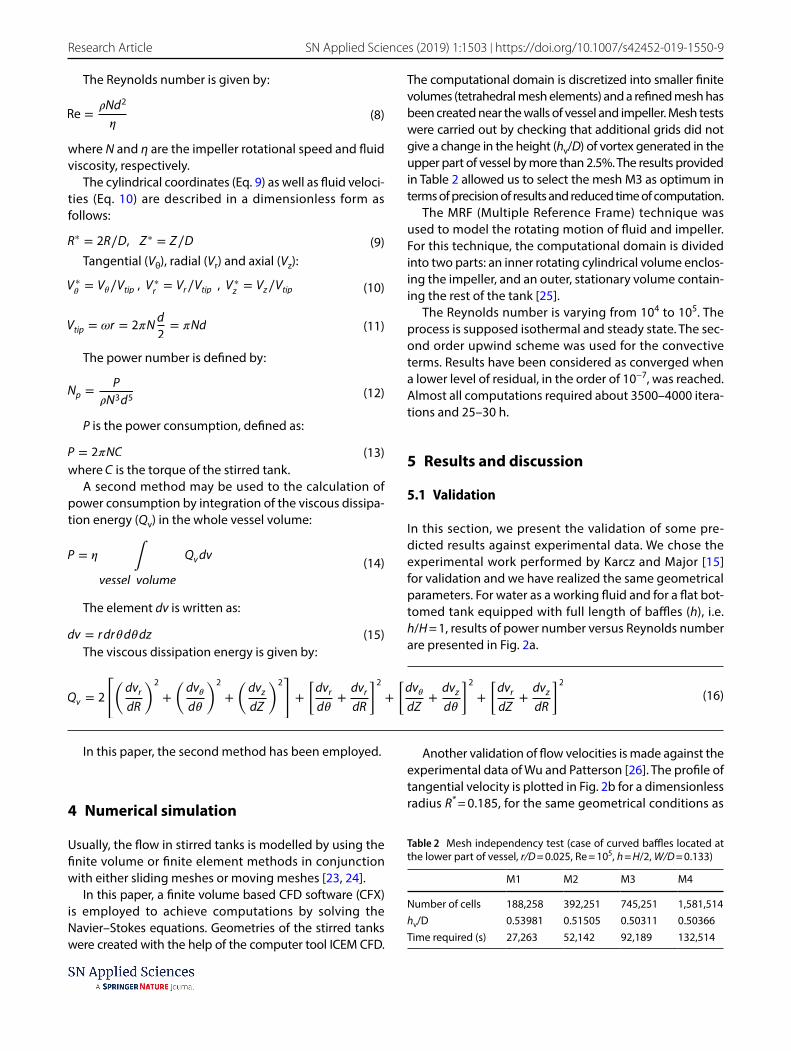
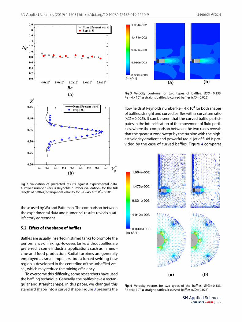
In this section, we present the validation of some pre‑dicted results against experimental data. We chose the experimental work performed by Karcz and Major [15] for validation and we have realized the same geometrical parameters. For water as a working fluid and for a flat bot‑tomed tank equipped with full length of baffles (h), i.e. h/H = 1, results of power number versus Reynolds number are presented in Fig. 2a.
Table 2 Mesh independency test (case of curved baffles located at the lower part of vessel, r/D = 0.025, Re = 105, h = H/2, W/D = 0.133)
M1 M2 M3 M4
Number of cells 188,258 392,251 745,251 1,581,514hv/D 0.53981 0.51505 0.50311 0.50366Time required (s) 27,263 52,142 92,189 132,514
Another validation of flow velocities is made against the experimental data of Wu and Patterson [26]. The profile of tangential velocity is plotted in Fig. 2b for a dimensionless radius R* = 0.185, for the same geometrical conditions as
Vol.:(0123456789)
SN Applied Sciences (2019) 1:1503 | https://doi.org/10.1007/s42452-019-1550-9 Research Article
those used by Wu and Patterson. The comparison between the experimental data and numerical results reveals a sat‑isfactory agreement.
5.2 Effect of the shape of baffles
Baffles are usually inserted in stirred tanks to promote the performance of mixing. However, tanks without baffles are preferred is some industrial applications such as in medi‑cine and food production. Radial turbines are generally employed as small impellers, but a forced swirling flow region is developed in the centerline of the unbaffled ves‑sel, which may reduce the mixing efficiency.
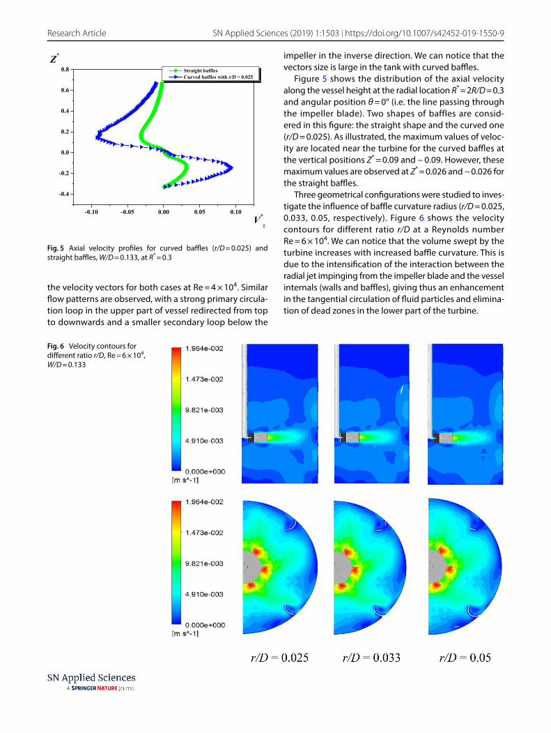
To overcome this difficulty, some researchers have used the baffling technique. Generally, the baffles have a rectan‑gular and straight shape; in this paper, we changed this standard shape into a curved shape. Figure 3 presents the
flow fields at Reynolds number Re = 4 × 10⁴ for both shapes of baffles: straight and curved baffles with a curvature ratio (r/D = 0.025). It can be seen that the curved baffle partici‑pates in the intensification of the movement of fluid parti‑cles, where the comparison between the two cases reveals that the greatest zone swept by the turbine with the high‑est velocity gradient and powerful radial jet of fluid is pro‑vided by the case of curved baffles. Figure 4 compares
4.0x10⁴ 8.0x10⁴ 1.2x10⁵ 1.6x10⁵ 2.0x1050.0
0.2
0.4
0.6
0.8
1.0
1.2
1.4
1.6
1.8
2.0 Num. [Present work] Exp. [15]
Re
Np
(a)
-0.1 0.0 0.1 0.2 0.3 0.4 0.5 0.6 0.70.20
0.25
0.30
0.35
0.40
0.45Z*
Vθ*
Num [Present work]Exp [26]
(b)
Fig. 2 Validation of predicted results against experimental data, a Power number versus Reynolds number (validation) for the full length of baffles, b tangential velocity for Re = 4 × 10⁴, R* = 0.185
Fig. 3 Velocity contours for two types of baffles, W/D = 0.133, Re = 4 × 10⁴, a straight baffles, b curved baffles (r/D = 0.025)
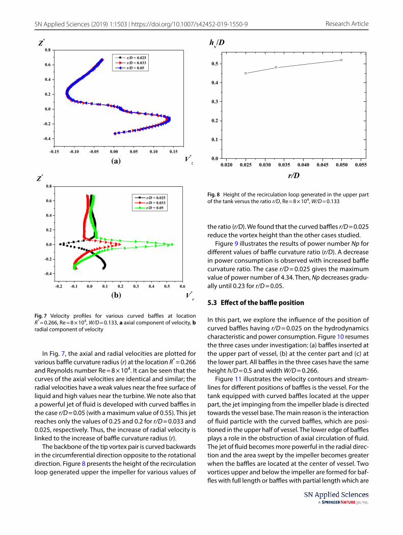
Fig. 4 Velocity vectors for two types of the baffles, W/D = 0.133, Re = 4 × 10⁴, a straight baffles, b curved baffles (r/D = 0.025)
Vol:.(1234567890)
Research Article SN Applied Sciences (2019) 1:1503 | https://doi.org/10.1007/s42452-019-1550-9
the velocity vectors for both cases at Re = 4 × 10⁴. Similar flow patterns are observed, with a strong primary circula‑tion loop in the upper part of vessel redirected from top to downwards and a smaller secondary loop below the
impeller in the inverse direction. We can notice that the vectors size is large in the tank with curved baffles.
Figure 5 shows the distribution of the axial velocity along the vessel height at the radial location R* = 2R/D = 0.3 and angular position θ = 0° (i.e. the line passing through the impeller blade). Two shapes of baffles are consid‑ered in this figure: the straight shape and the curved one (r/D = 0.025). As illustrated, the maximum values of veloc‑ity are located near the turbine for the curved baffles at the vertical positions Z* = 0.09 and − 0.09. However, these maximum values are observed at Z* = 0.026 and − 0.026 for the straight baffles.
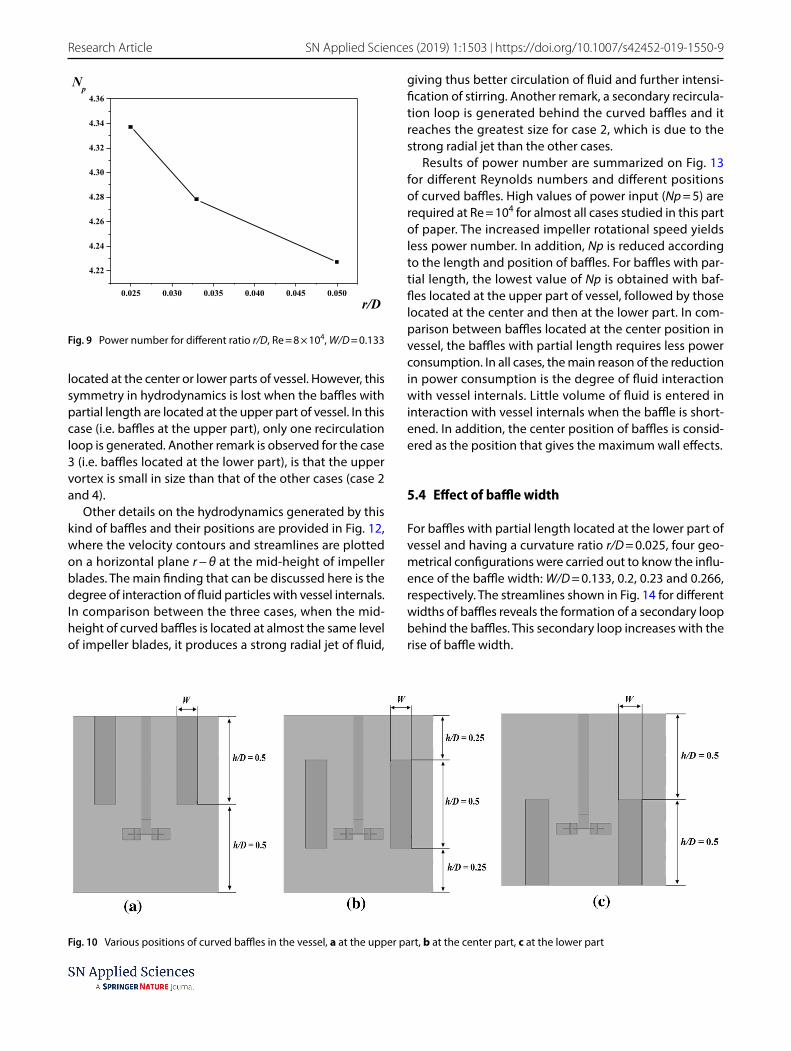
Three geometrical configurations were studied to inves‑tigate the influence of baffle curvature radius (r/D = 0.025, 0.033, 0.05, respectively). Figure 6 shows the velocity contours for different ratio r/D at a Reynolds number Re = 6 × 10⁴. We can notice that the volume swept by the turbine increases with increased baffle curvature. This is due to the intensification of the interaction between the radial jet impinging from the impeller blade and the vessel internals (walls and baffles), giving thus an enhancement in the tangential circulation of fluid particles and elimina‑tion of dead zones in the lower part of the turbine.
-0.10 -0.05 0.00 0.05 0.10
-0.4
-0.2
0.0
0.2
0.4
0.6
0.8Z*
V*z
Straight bafflesCurved baffles with r/D = 0.025
Fig. 5 Axial velocity profiles for curved baffles (r/D = 0.025) and straight baffles, W/D = 0.133, at R* = 0.3
Fig. 6 Velocity contours for different ratio r/D, Re = 6 × 10⁴, W/D = 0.133
Vol.:(0123456789)
SN Applied Sciences (2019) 1:1503 | https://doi.org/10.1007/s42452-019-1550-9 Research Article
In Fig. 7, the axial and radial velocities are plotted for various baffle curvature radius (r) at the location R* = 0.266 and Reynolds number Re = 8 × 10⁴. It can be seen that the curves of the axial velocities are identical and similar; the radial velocities have a weak values near the free surface of liquid and high values near the turbine. We note also that a powerful jet of fluid is developed with curved baffles in the case r/D = 0.05 (with a maximum value of 0.55). This jet reaches only the values of 0.25 and 0.2 for r/D = 0.033 and 0.025, respectively. Thus, the increase of radial velocity is linked to the increase of baffle curvature radius (r).
The backbone of the tip vortex pair is curved backwards in the circumferential direction opposite to the rotational direction. Figure 8 presents the height of the recirculation loop generated upper the impeller for various values of
the ratio (r/D). We found that the curved baffles r/D = 0.025 reduce the vortex height than the other cases studied.
Figure 9 illustrates the results of power number Np for different values of baffle curvature ratio (r/D). A decrease in power consumption is observed with increased baffle curvature ratio. The case r/D = 0.025 gives the maximum value of power number of 4.34. Then, Np decreases gradu‑ally until 0.23 for r/D = 0.05.
5.3 Effect of the baffle position
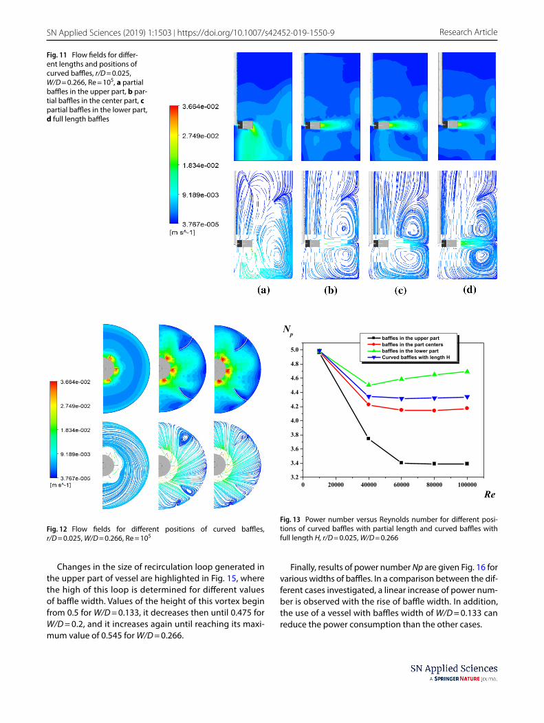
In this part, we explore the influence of the position of curved baffles having r/D = 0.025 on the hydrodynamics characteristic and power consumption. Figure 10 resumes the three cases under investigation: (a) baffles inserted at the upper part of vessel, (b) at the center part and (c) at the lower part. All baffles in the three cases have the same height h/D = 0.5 and width W/D = 0.266.
Figure 11 illustrates the velocity contours and stream‑lines for different positions of baffles is the vessel. For the tank equipped with curved baffles located at the upper part, the jet impinging from the impeller blade is directed towards the vessel base. The main reason is the interaction of fluid particle with the curved baffles, which are posi‑tioned in the upper half of vessel. The lower edge of baffles plays a role in the obstruction of axial circulation of fluid. The jet of fluid becomes more powerful in the radial direc‑tion and the area swept by the impeller becomes greater when the baffles are located at the center of vessel. Two vortices upper and below the impeller are formed for baf‑fles with full length or baffles with partial length which are
-0.15 -0.10 -0.05 0.00 0.05 0.10 0.15
-0.4
-0.2
0.0
0.2
0.4
0.6
0.8Z*
V*z
r/D = 0.025r/D = 0.033r/D = 0.05
(a)
-0.2 -0.1 0.0 0.1 0.2 0.3 0.4 0.5 0.6
-0.4
-0.2
0.0
0.2
0.4
0.6
0.8
r/D = 0.025r/D = 0.033r/D = 0.05
Z*
V*r
(b)
Fig. 7 Velocity profiles for various curved baffles at location R* = 0.266, Re = 8 × 10⁴, W/D = 0.133, a axial component of velocity, b radial component of velocity
0.020 0.025 0.030 0.035 0.040 0.045 0.050 0.0550.0
0.1
0.2
0.3
0.4
0.5
hv/D
r/D
Fig. 8 Height of the recirculation loop generated in the upper part of the tank versus the ratio r/D, Re = 8 × 10⁴, W/D = 0.133
Vol:.(1234567890)
Research Article SN Applied Sciences (2019) 1:1503 | https://doi.org/10.1007/s42452-019-1550-9
located at the center or lower parts of vessel. However, this symmetry in hydrodynamics is lost when the baffles with partial length are located at the upper part of vessel. In this case (i.e. baffles at the upper part), only one recirculation loop is generated. Another remark is observed for the case 3 (i.e. baffles located at the lower part), is that the upper vortex is small in size than that of the other cases (case 2 and 4).
Other details on the hydrodynamics generated by this kind of baffles and their positions are provided in Fig. 12, where the velocity contours and streamlines are plotted on a horizontal plane r − θ at the mid‑height of impeller blades. The main finding that can be discussed here is the degree of interaction of fluid particles with vessel internals. In comparison between the three cases, when the mid‑height of curved baffles is located at almost the same level of impeller blades, it produces a strong radial jet of fluid,
giving thus better circulation of fluid and further intensi‑fication of stirring. Another remark, a secondary recircula‑tion loop is generated behind the curved baffles and it reaches the greatest size for case 2, which is due to the strong radial jet than the other cases.
Results of power number are summarized on Fig. 13 for different Reynolds numbers and different positions of curved baffles. High values of power input (Np = 5) are required at Re = 104 for almost all cases studied in this part of paper. The increased impeller rotational speed yields less power number. In addition, Np is reduced according to the length and position of baffles. For baffles with par‑tial length, the lowest value of Np is obtained with baf‑fles located at the upper part of vessel, followed by those located at the center and then at the lower part. In com‑parison between baffles located at the center position in vessel, the baffles with partial length requires less power consumption. In all cases, the main reason of the reduction in power consumption is the degree of fluid interaction with vessel internals. Little volume of fluid is entered in interaction with vessel internals when the baffle is short‑ened. In addition, the center position of baffles is consid‑ered as the position that gives the maximum wall effects.
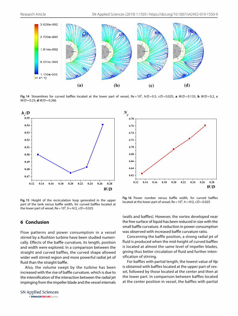
5.4 Effect of baffle width
For baffles with partial length located at the lower part of vessel and having a curvature ratio r/D = 0.025, four geo‑metrical configurations were carried out to know the influ‑ence of the baffle width: W/D = 0.133, 0.2, 0.23 and 0.266, respectively. The streamlines shown in Fig. 14 for different widths of baffles reveals the formation of a secondary loop behind the baffles. This secondary loop increases with the rise of baffle width.
0.025 0.030 0.035 0.040 0.045 0.050
4.22
4.24
4.26
4.28
4.30
4.32
4.34
4.36
Np
r/D
Fig. 9 Power number for different ratio r/D, Re = 8 × 10⁴, W/D = 0.133
Fig. 10 Various positions of curved baffles in the vessel, a at the upper part, b at the center part, c at the lower part
Vol.:(0123456789)
SN Applied Sciences (2019) 1:1503 | https://doi.org/10.1007/s42452-019-1550-9 Research Article
Changes in the size of recirculation loop generated in the upper part of vessel are highlighted in Fig. 15, where the high of this loop is determined for different values of baffle width. Values of the height of this vortex begin from 0.5 for W/D = 0.133, it decreases then until 0.475 for W/D = 0.2, and it increases again until reaching its maxi‑mum value of 0.545 for W/D = 0.266.
Finally, results of power number Np are given Fig. 16 for various widths of baffles. In a comparison between the dif‑ferent cases investigated, a linear increase of power num‑ber is observed with the rise of baffle width. In addition, the use of a vessel with baffles width of W/D = 0.133 can reduce the power consumption than the other cases.
Fig. 11 Flow fields for differ‑ent lengths and positions of curved baffles, r/D = 0.025, W/D = 0.266, Re = 105, a partial baffles in the upper part, b par‑tial baffles in the center part, c partial baffles in the lower part, d full length baffles
Fig. 12 Flow fields for different positions of curved baffles, r/D = 0.025, W/D = 0.266, Re = 105
0 20000 40000 60000 80000 1000003.2
3.4
3.6
3.8
4.0
4.2
4.4
4.6
4.8
5.0
Np
Re
baffles in the upper partbaffles in the part centersbaffles in the lower partCurved baffles with length H
Fig. 13 Power number versus Reynolds number for different posi‑tions of curved baffles with partial length and curved baffles with full length H, r/D = 0.025, W/D = 0.266
Vol:.(1234567890)
Research Article SN Applied Sciences (2019) 1:1503 | https://doi.org/10.1007/s42452-019-1550-9
6 Conclusion
Flow patterns and power consumption in a vessel stirred by a Rushton turbine have been studied numeri‑cally. Effects of the baffle curvature, its length, position and width were explored. In a comparison between the straight and curved baffles, the curved shape allowed wider well stirred region and more powerful radial jet of fluid than the straight baffle.
Also, the volume swept by the turbine has been increased with the rise of baffle curvature, which is due to the intensification of the interaction between the radial jet impinging from the impeller blade and the vessel internals
(walls and baffles). However, the vortex developed near the free surface of liquid has been reduced in size with the small baffle curvature. A reduction in power consumption was observed with increased baffle curvature ratio.
Concerning the baffle position, a strong radial jet of fluid is produced when the mid‑height of curved baffles is located at almost the same level of impeller blades, giving thus better circulation of fluid and further inten‑sification of stirring.
For baffles with partial length, the lowest value of Np is obtained with baffles located at the upper part of ves‑sel, followed by those located at the center and then at the lower part. In comparison between baffles located at the center position in vessel, the baffles with partial
Fig. 14 Streamlines for curved baffles located at the lower part of vessel, Re = 105, h/D = 0.5, r/D = 0.025, a W/D = 0.133, b W/D = 0.2, c W/D = 0.23, d W/D = 0.266
0.12 0.14 0.16 0.18 0.20 0.22 0.24 0.26 0.28
0.47
0.48
0.49
0.50
0.51
0.52
0.53
0.54
0.55hv/D
W/D
Fig. 15 Height of the recirculation loop generated in the upper part of the tank versus baffle width, for curved baffles located at the lower part of vessel, Re = 105, h = H/2, r/D = 0.025
0.12 0.14 0.16 0.18 0.20 0.22 0.24 0.26 0.28
4.62
4.64
4.66
4.68
4.70
4.72
4.74
4.76
4.78
Np
W/D
Fig. 16 Power number versus baffle width, for curved baffles located at the lower part of vessel, Re = 105, h = H/2, r/D = 0.025
Vol.:(0123456789)
SN Applied Sciences (2019) 1:1503 | https://doi.org/10.1007/s42452-019-1550-9 Research Article
length requires less power consumption. In all cases, the main reason of the reduction in power consumption is the degree of fluid interaction with vessel internals.
Concerning the effect of baffle width, the increase of this parameter yields wider secondary loops which are developed behind baffles and requires further power consumption. So the case W/D = 0.133 is recommended in this situation.
Compliance with ethical standards
Conflict of interest The authors declare that they have no conflict of interest.
References
1. Kumaresan T, Joshi JB (2006) Effect of impeller design on the flow pattern and mixing in stirred tanks. Chem Eng J 115:173–193
2. Ameur H (2016) Effect of the shaft eccentricity and rotational direction on the mixing characteristics in cylindrical tank reac‑tors. Chin J Chem Eng 24:1647–1654
3. Hadjeb A, Bouzit M, Kamla Y, Ameur H (2017) A new geometri‑cal model for mixing of highly viscous fluids by combining two‑blade and helical screw agitators. Polish J Chem Technol 19:83–91
4. Ameur H (2019) Some modifications in the Scaba 6SRGT impeller to enhance the mixing characteristics of Hershel–Bulkley fluids. Food Bioprod Process 117:302–309
5. Youcefi S, Bouzit M, Ameur H, Kamla Y, Youcefi A (2013) Effect of some design parameters on the flow fields and power con‑sumption in a vessel stirred by a Rushton turbine. Chem Pro‑cess Eng 34:293–307
6. Zamiri A, Chung JT (2018) Numerical evaluation of turbulent flow structures in a stirred tank with a Rushton turbine based on scale‑adaptive simulation. Comput Fluids 170:236–248
7. Tamburini A, Gagliano G, Micale G, Brucato A, Scargiali F, Cio‑falo M (2018) Direct numerical simulations of creeping to early turbulent flow in unbaffled and baffled stirred tanks. Chem Eng Sci 192:161–175
8. Montante G, Lee KC, Brucato A, Yianneskis M (2001) Numerical simulations of the dependency of flow pattern on impeller clearance in stirred vessel. Chem Eng Sci 56:3751–3770
9. Ameur H (2015) Energy efficiency of different impellers in stirred tank reactors. Energy 93:1980–1988
10. Ameur H, Kamla Y, Sahel D (2016) CFD simulations of mix‑ing characteristics of radial impellers in cylindrical reactors. ChemistrySelect 1:2548–2551
11. Beloudane M, Bouzit M, Ameur H (2018) Numerical investi‑gation of the turbulent flow generated with a radial turbine using a converging hollow blade. Polish J Chem Technol 20:129–137
12. Foukrach M, Bouzit M, Ameur H, Kamla Y (2019) Influence of the vessel shape on the performance of a mechanically agi‑tated system. Chem Pap 73:469–480
13. Buwa V, Dewan A, Nassar AF, Durst F (2006) Fluid dynamics and mixing of single‑phase flow in a stirred vessel with a grid disc impeller: experimental and numerical investigations. Chem Eng Sci 61:2815–2822
14. Bittins K, Zehner P (1994) Power and discharge numbers of radial‑flow impellers. Fluid‑dynamic interactions between impeller and baffles. Chem Eng Process 33:295–301
15. Karcz J, Major M (1998) An effect of a baffle length on the power consumption in an agitated vessel. Chem Eng Process 37:249–256
16. Ammar M, Driss Z, Chtourou W, Abid M (2011) Effects of baffle length on turbulent flows generated in stirred vessels. Cent Eur J Eng 1:401–412
17. Kamla K, Bouzit M, Ameur H, Arab MI, Hadjeb A (2017) Effect of the inclination of baffles on the power consumption and fluid flows in a vessel stirred by a Rushton turbine. Chin J Mech Eng 30:1008–1016
18. Karcz J, Stręk F (1995) Heat transfer in jacketed agitated vessels equipped with nonstandard baffles. Chem Eng J 58:135–143
19. Lu WM, Wu HZ, Ju MY (1997) Effects of baffle design on the liquid mixing in an aerated stirred tank with standard Rushton turbine impellers. Chem Eng Sci 52:3843–3851
20. Karcz J, Mackiewicz B (2009) Effects of vessel baffling on the drawdown of floating solids. Chem Pap 63:164–171
21. Major‑Godlewska M, Karcz J (2018) Power consumption for an agitated vessel equipped with pitched blade turbine and short baffles. Chem Pap 72:1081–1088
22. Devi TT, Kumar B (2012) CFD simulation of flow patterns in unbaffled stirred tank with CD‑6 impeller. Chem Ind Chem Eng Q 18:535–546
23. Deglon DA, Meyer J (2006) CFD modelling of stirred tanks: numerical considerations. Mineral Eng 19:1059–1068
24. Torré J‑P, Fletcher DF, Lasuye T, Xuereb C (2007) Single and mul‑tiphase CFD approaches for modelling partially baffled stirred vessels: comparison of experimental data with numerical pre‑dictions. Chem Eng Sci 62:6246–6262
25. Ochieng A, Onyango MS (2010) CFD simulation of the hydrody‑namics and mixing time in a stirred tank. Chem Ind Chem Eng Q 16:379–386
26. Wu H, Patterson GK (1989) Laser‑Doppler measurements of turbulent flow parameters in a stirred mixer. Chem Eng Sci 44:2207–2221
Publisher’s Note Springer Nature remains neutral with regard to jurisdictional claims in published maps and institutional affiliations.


![Experimental Investigation of Ba e E ect on the Flow in a ...scientiairanica.sharif.edu/article_3326_457545225e84e1ee2ed6f636… · Schroeder [15] on primary sedimentation tanks showed](https://img.pdfslide.us/doc/110x75/5fbb48f3fc31be42595e6bc9/experimental-investigation-of-ba-e-e-ect-on-the-flow-in-a-schroeder-15-on.jpg)