Embed Size (px)
Citation preview
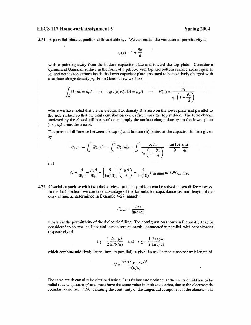
EECS 117 Homework Assignment 5 Spring 2004
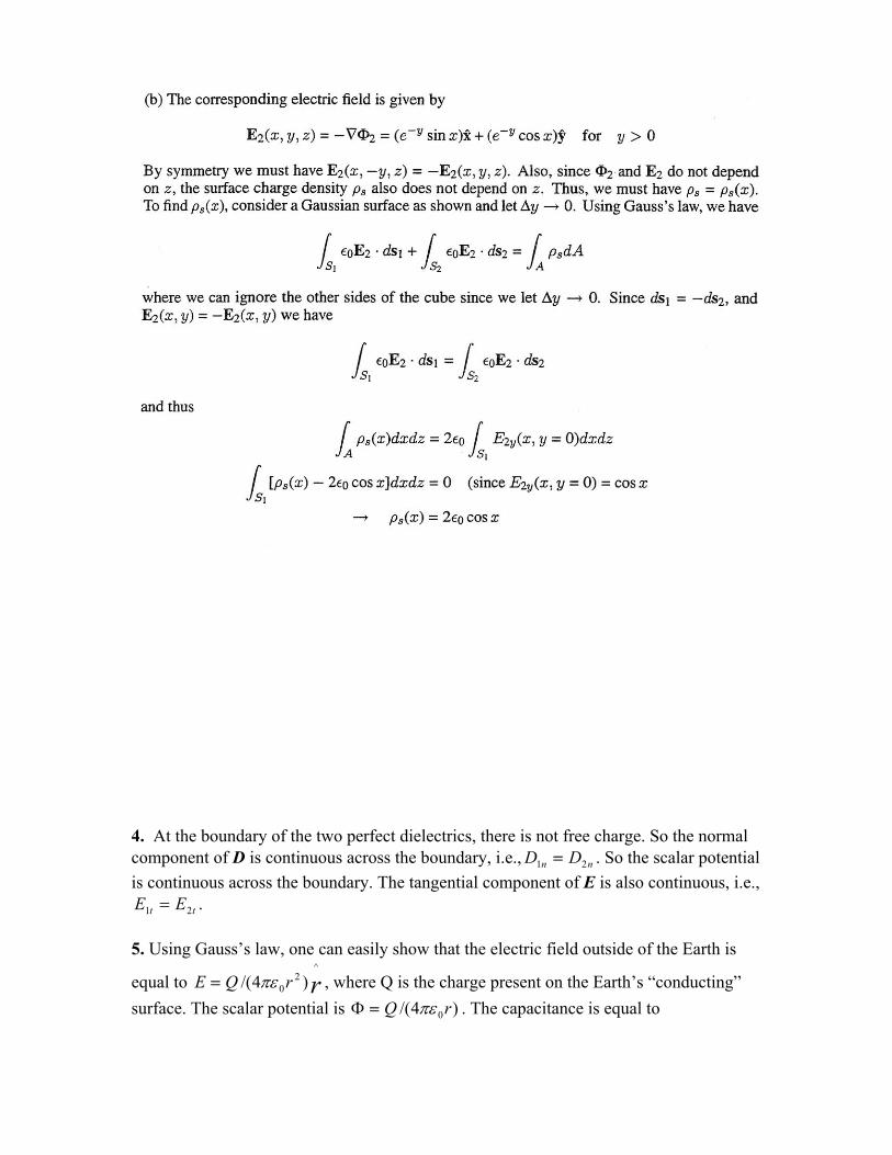
4. At the boundary of the two perfect dielectrics, there is not free charge. So the normal component of D is continuous across the boundary, i.e., nn DD 21 = . So the scalar potential is continuous across the boundary. The tangential component of E is also continuous, i.e.,
. tt EE 21 = 5. Using Gauss’s law, one can easily show that the electric field outside of the Earth is
equal to , where Q is the charge present on the Earth’s “conducting” surface. The scalar potential is
rrQE^
20 )4/( πε=
)4/( 0rQ πε=Φ . The capacitance is equal to
aarQC 04)(/ πε=== Φ
aQE 0max 4/(= πε
, where a is the radius of the Earth. Evaluation of the expression yields C = 709 µF.
1 22
2
∂∂
=Φ∇ rrr
1 )(r =Φ
2 )(r =Φ
ΦΦ
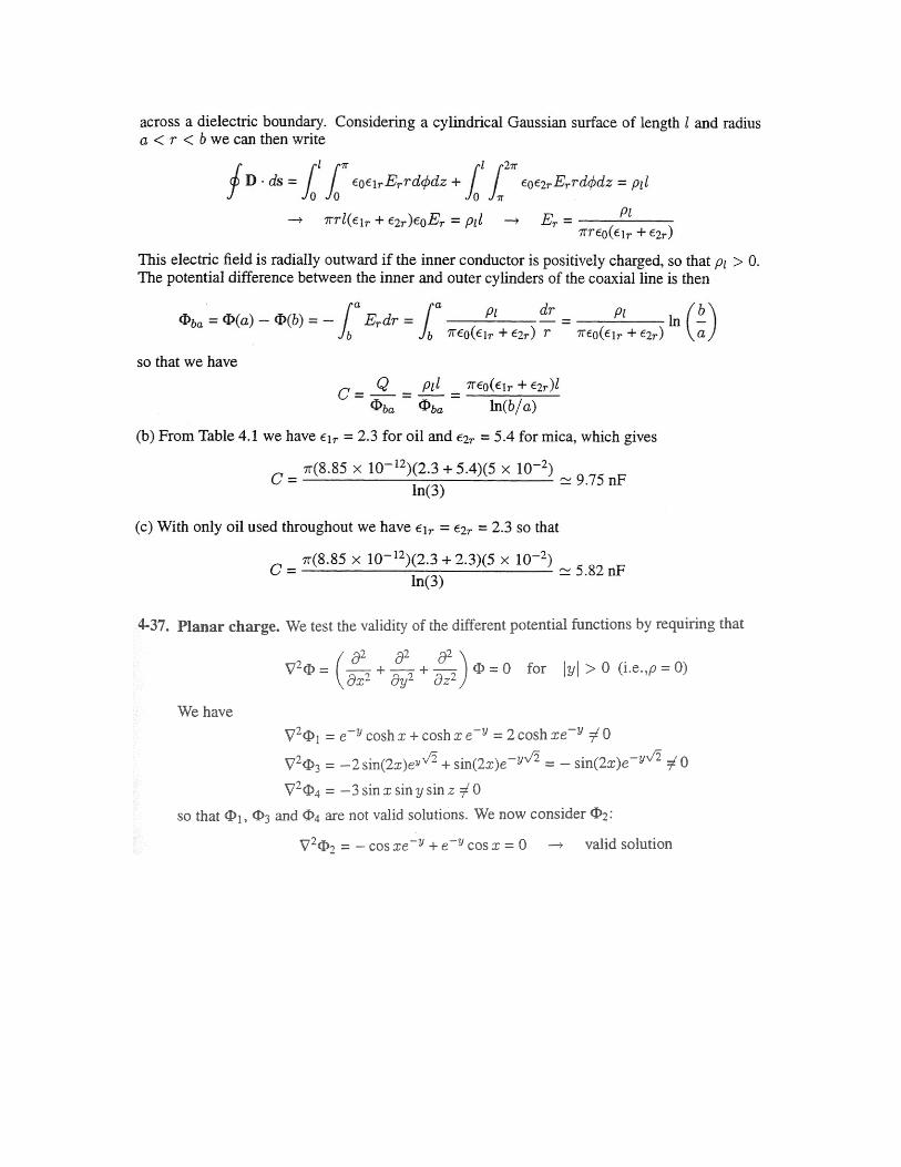
(b) The air typically can sustain an electric field of 3 x 10⁶ V/m before breakdown. This would imply that the maximum charge that can be put onto the Earth is governed by
CaQ 1020
6max
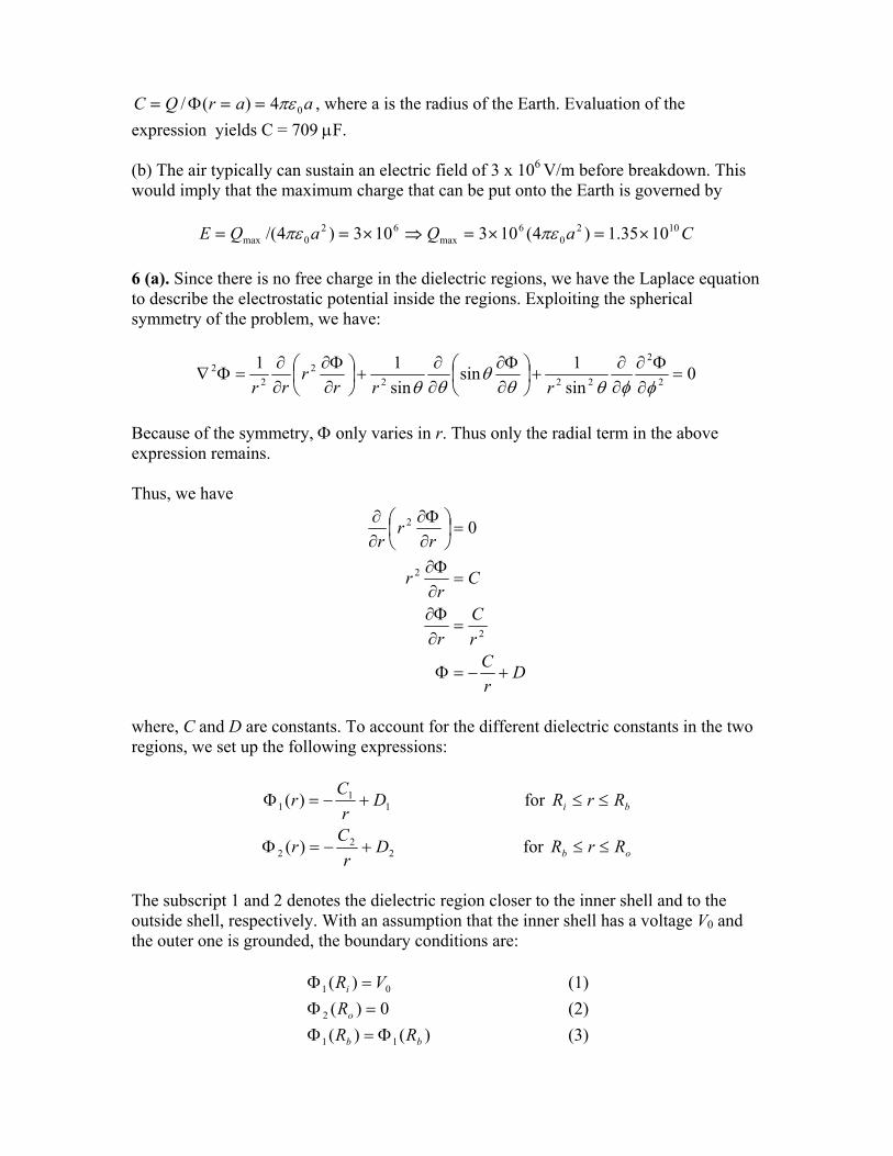
62 1035.1)4(103103) ×=×=⇒×= πε 6 (a). Since there is no free charge in the dielectric regions, we have the Laplace equation to describe the electrostatic potential inside the regions. Exploiting the spherical symmetry of the problem, we have:
0sin1sin
sin1
2
2
222 =∂Φ∂
∂∂
+
∂Φ∂
∂∂
+
∂Φ∂
φφθθθ
θθ rrr
Because of the symmetry, Φ only varies in r. Thus only the radial term in the above expression remains. Thus, we have
DrC
rC
r
Cr
r
rr
r
+−=Φ
=∂Φ∂
=∂Φ∂
=
∂Φ∂
∂∂
2
2
2 0
where, C and D are constants. To account for the different dielectric constants in the two regions, we set up the following expressions:
11 D
rC
+− for rR bi R≤≤
22 D
rC
+− for rR ob R≤≤
The subscript 1 and 2 denotes the dielectric region closer to the inner shell and to the outside shell, respectively. With an assumption that the inner shell has a voltage V0 and the outer one is grounded, the boundary conditions are:
01 )( VRi = (1) 0)(2 =oR (2)
)()( 11 bb RR Φ=Φ (3)
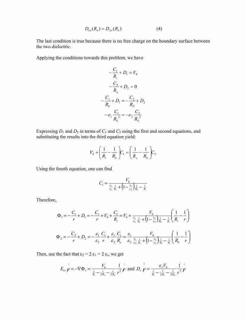
)()( 21 bnbn RDRD = (4) The last condition is true because there is no free charge on the boundary surface between the two dielectric. Applying the conditions towards this problem, we have
011 VD
RC
i
=+−
022 =+− D
RC
o
22
11 D
RCD
RC
bb
+−=+−
22
221
1bb R
CRC
εε −=−
Expressing D1 and D2 in terms of C1 and C2 using the first and second equations, and substituting the results into the third equation yield:
2101111 CRR
CRR
Vbobi
−=
−+
Using the fourth equation, one can find
( )ibo RRR
VC111
01
2
1
2
1 1 −−+=
εε
εε
Therefore,
( )
−
−−++=++−=+−=
rRVV
RCV
rCD
rC
iRRRi ibo
111 111
00
10
11
11
2
1
2
1εε
εεΦ
( )
−
−−+=+−=+−=
rRV
RC
rCD
rC
ibo RRRo
111 0
1110
2
11
2
11
2
12
22
2
1
2
1εε
εεε
εεε
εε
Φ
Then, use the fact that ε2 = 2 ε1 = 2 εr, we get
rr rVE
boi RRRr
^
22
12
110
1
^
11
−−=−∇= Φ and rr r
VD
boi RRR
rr
^
22
12
110
^ 1−−
=ε
rr rVE
boi RRRr
^
21120
1
^
21
−−=−∇= Φ and rr r
VDboi RRR
rr
^
22
12
110
^ 1−−
=ε
(b) The surface density of the inner shell is given by
22
12
110
^
1
^ 1)(iRRR
rirsi R
VRrD
boi
rr −−==⋅=
ερ
The capacitance is then equal to
boi RRR
rsii
VR
VQC
21
211
0
2
0
44−−
===περπ
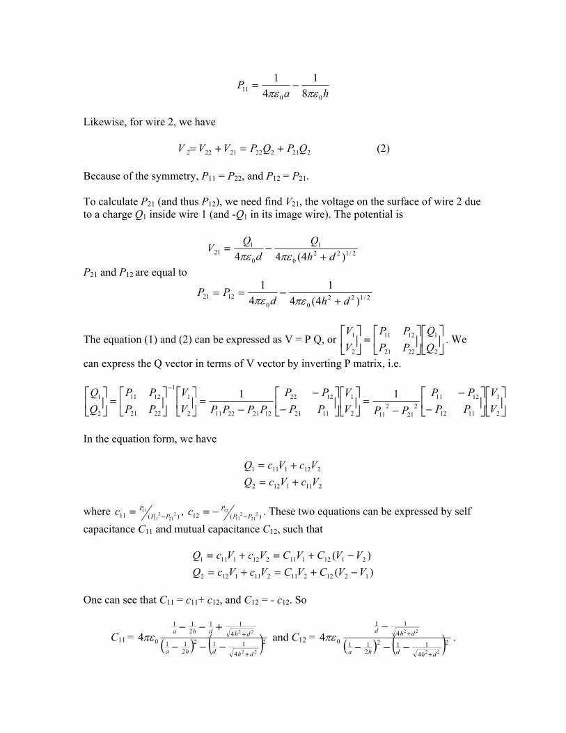
7. The problem can be analyzed using method of image, namely the ground plane can be replaced by two image wires distance h below the ground.
2
h
d 1
In general, the voltage on the surface of the wire 1 is given by
21211112111 QPQPVVV +=+= (1) V11 is the voltage on the surface of the wire 1 due to a charge Q1 in the wire 1 (and -Q1 in its image wire), and V12 is the voltage of wire 1 due to a charge Q2 in the wire 2 (and –Q2 in its image wire). To find V11, we neglect wire 2 and calculate the potential on the wire surface due to a charge Q1 inside the wire and an image charge –Q1. This potential is same as the one due to a dipole evaluated on the surface of the positive charge.
hQ
aQ
V0
1
0
111 84 πεπε
−=
or
haP
0011 8
14
1πεπε
−=
Likewise, for wire 2, we have
22122221222 QPQPVVV +=+= (2) Because of the symmetry, P11 = P22, and P12 = P21. To calculate P21 (and thus P12), we need find V21, the voltage on the surface of wire 2 due to a charge Q1 inside wire 1 (and -Q1 in its image wire). The potential is
2/1220
1
0
121 )4(44 dh
Qd
QV
+−=
πεπε
P21 and P12 are equal to
2/12200
1221 )4(41
41
dhdPP
+−==
πεπε
The equation (1) and (2) can be expressed as V = P Q, or . We
can express the Q vector in terms of V vector by inverting P matrix, i.e.
=
2
1
2221
1211
2
1
PPPP
VV
−
−
−=
−
−−
=
=
−
2
1
1112
12112
212
112
1
1121
1222
122122112
11
2221
1211
2
1 11VV
PPPP
PPVV
PPPP
PPPPVV
PPPP
In the equation form, we have
2111122
2121111
VcVcQVcVcQ
+=+=
where )(11 2
212
11
11PP
P−=c , )(12 2
212
11
12PP
P−−=c . These two equations can be expressed by self
capacitance C11 and mutual capacitance C12, such that
)()(
12122112111122
21121112121111
VVCVCVcVcQVVCVCVcVcQ−+=+=−+=+=
One can see that C11 = c11+ c12, and C12 = - c12. So
C11 = ( ) ( )24
112211
411
211
022
22
4dhdha
dhdha
+
+
−−−
+−−πε and C12 = ( ) ( )2
4112
211
411
022
22
4dhdha
dhd
+
+
−−−
−πε .
8(a). In both dielectric-filled and vacuum-filled capacitor areas, the electric field is equal
to -V0/d , where y axis is pointing up normal to the capacitor plates. But in the dielectric
region, D = ε
j^
r E = - εr V0/d and ρj^
s = - εr V0/d. The vacuum region has D = ε0 E = - ε0
V0/d and ρj^
s = - ε0 V0/d. (b). The electrostatic energy Ud stored inside the dielectric region is equal to
xwd
Vxdw
EU rr
d 22
20
2εε
== . By the same token, The electrostatic energy Ud stored
inside the vacuum region is described by wxld
Vdwxl
Ed )(
2)(
2
200
20 −=−=
εεU . The
value of x for equal amount of energy stored in each region is given by 0//)( εε rxxl =− , or )/( 00 rlx εεε += .