Embed Size (px)
Citation preview
3/4/2018
1
EE140 Introduction to
Communication Systems
Lecture 7
Instructor: Prof. Xiliang Luo
ShanghaiTech University, Spring 20181
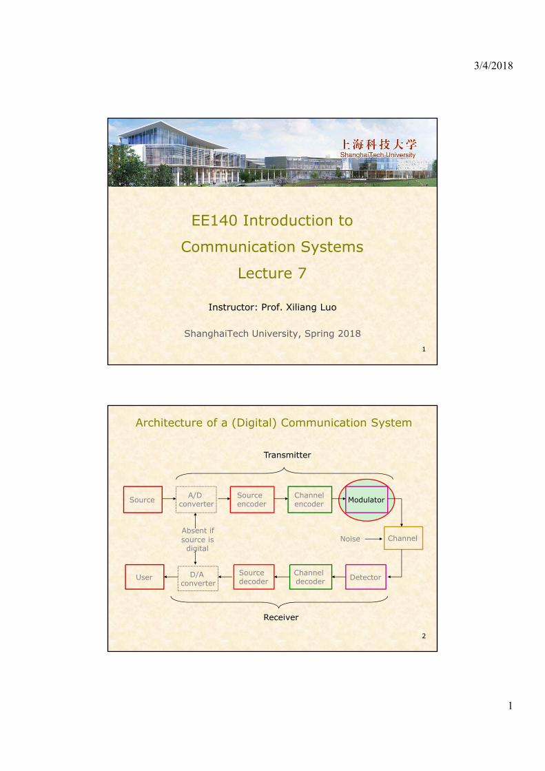
Architecture of a (Digital) Communication System
2
Source A/Dconverter
Sourceencoder
Channelencoder Modulator
Channel
DetectorChanneldecoder
Sourcedecoder
D/Aconverter
User
Transmitter
Receiver
Absent ifsource isdigital
Noise

3/4/2018
2
Contents
• Analog Modulation
– Amplitude modulation
• DSB
• SSB
• VSB
– Pulse modulation
– Angle modulation (phase/frequency)
3
Examples of Analog Modulation
4

3/4/2018
3
Modulation• What is modulation?
– Transform a message into another signal to facilitate transmission over a communication channel• Generate a carrier signal at the transmitter• Modify some characteristics of the carrier with the
information to be transmitted• Detect the modifications at the receiver
• Why modulation?– Frequency translation– Frequency-division multiplexing– Noise performance improvement
5
Analog Modulation• Characteristics that can be modified in the carrier
– Amplitude
– Frequency
– Phase
6
Amplitude modulation
Angle modulation
AMPM
)t(t)t(fcos)t(A)t(C θπ 2

3/4/2018
4
Amplitude Modulation• Double-sideband suppressed-carrier AM (DSB-SC)
– Baseband signal (modulating wave):
– Carrier wave
– Modulated wave
7
)t(m
02 θπ ftcosA)t(C
02 θπ ftcos)t(Am)t(C)t(m)t(S
DSB-SC Spectrum
8
)ff(M)ff(MA)f(S cc 2
1

3/4/2018
5
Demodulation of DSB-SC Signals• Phase-coherent demodulation
9
24
2 2 2
tfcos)t(m)t(mA
tfcosA)t(mtfcosA)t(s)t(r
c
cc
π
ππ
s(t) v(t) vo(t)Product modulator
Low-pass filter
cos(2πfct)
PLL (phase-locked loop)Local
oscillator
Demodulation of DSB-SC Signals• DSB-SC demodulation: graphic interpretation
10

3/4/2018
6
Question: not Phase Coherent?• Phase error
11
)t(m)tfcos(A)t(mcosA
)tfcos(tfcos)t(Am)tfcos()t(s)t(r
c
ccc
θπθ
θππθπ
42
1
2
1
22 2
42
1
2
1)t(mtfcosA)t(Am)t(r cπ
Uncertainty in the amplitude
Another Way to Generate DSB-SC Signals
12
A signalspectrum canbe translatedan amountby multiplyingthe signal withany periodicwave formwhosefundamentalfrequency is
cω
cω

3/4/2018
7
Double-sideband, Large-carrier (DSB-LC)
• DSB-LC signal (conventional AM signal) = DSB-SC signal + a carrier term
13
tcosAtcos)t(m)t(s cc ωω
Graphic Interpretation• DSB-LC signal
14
Tim
e do
mai
n
Freq
uenc
y do
mai
n

3/4/2018
8
DSB-LC Properties
• The role played by parameter A– If A is larger enough, say , the envelope of the
modulated waveform will be proportional to .
• The DC response of the signal has been lost in the demodulation as a result of the addition of the carrier.
15
)t(mminA )t(m
)t(m
Modulation Index• Modulation index m is a dimensionless scale factor
and used to represent the relative magnitudes of the sideband and carrier portion of the modulated signal.
• When m<1, and we also have
16
0
amplitude carrier peak
amplitude SC-DSB peak
A
)t(mmaxm
)t(mmin)t(m)t(m)t(mmax
magnitude) (min.magnitude) (max.
magnitude) (min.-magnitude) (max.
m

3/4/2018
9
Modulation Index (cont’d)
17
Demodulation of DSB-LC Signals• Coherent demod: possible, but not easy.
– Phase and frequency synchronizations are required;
• Noncoherent demod: envelope detection– The RC circuit can perform low pass filtering– Condition: or
18
The simplicity of envelop detector has madeConventional AM a practical choice for AM-radio broadcasting
RC too large
Correct RC
RC too small
)t(mminA 1m

3/4/2018
10
Transmission Efficiency• Transmission (modulation) efficiency:
• If , we have . The transmission efficiency
– Because , the transmission efficiency of a DSB-LC system is at best 33.3%. That is, at least 67% of the total power is expended in the carrier and wasted as the carrier term does not contain any information.
– For comparison, the transmission efficiency of a DSB-SC system is 100%.
19
)t(mA
)t(m
P
P
t
s
22
2
μ
tcosmA)t(m cω 222 mA)t(m
2
2
2 m
m
η
1m
Single-sideband (SSB) Modulation• DSB modulation results in a doubling of the
bandwidth of a given signal.
• Each pair of sidebands (i.e. upper or lower) contains the complete information of the original signal.
• The original signal can be recovered again from either the upper or lower pair of sidebands by an appropriate frequency translation. single-sideband modulation
20

3/4/2018
11
SSB• Advantage: SSB
modulation is efficient because it requires no more bandwidth than that of the original signal and only half that of the corresponding DSB signal.
21
Generation of SSB-SC Signals• Generation of SSB-SC signals• Method 1: filtering
– generate a DSB-SC signal;– filter out one pair of sidebands (upper or lower).
• Requirement of method 1: – does not contain significant low-frequency components;– the sideband filter is usually built at a dictated frequency.
22
3/4/2018
12
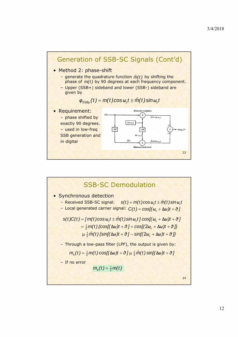
Generation of SSB-SC Signals (Cont’d)• Method 2: phase-shift
– generate the quadrature function by shifting the phase of by 90 degrees at each frequency component.
– Upper (SSB+) sideband and lower (SSB-) sideband are given by
• Requirement: – phase shifted by exactly 90 degrees.– used in low-freqSSB generation and in digital
23
)t(m)t(m̂
tsin)t(m̂tcos)t(m)t( ccSSB ωωφ
SSB-SC Demodulation• Synchronous detection
– Received SSB-SC signal: – Local generated carrier signal:
– Through a low-pass filter (LPF), the output is given by:
– If no error
24
tsin)t(m̂tcos)t(m)t(s cc ωω ]t)cos[()t(C c θωω Δ
]}t)sin[(]t){sin[()t(m̂
]}t)cos[(]t){cos[()t(m
]t)cos[(]tsin)t(m̂tcos)t(m[)t(C)t(s
c
c
ccc
θωωθω
θωωθω
θωωωω
ΔΔ
ΔΔ
Δ
2
2
21
21
]t)sin[()t(m̂]t)cos[()t(m)t(me θωθω ΔΔ 21
21
21 )t(m)t(me

3/4/2018
13
SSB-SC Demodulation (Cont’d)• Frequency domain graphic interpretation
25
Single-sideband, Large-carrier (SSB-LC)• SSB-LC signal: SSB-SC signal + a carrier term• In time domain:
– The frequency response at DC is NOT desired.
• Synchronous detection: √• Envelope detection, not straightforward
– Requirement of envelope detection: the carrier is much larger than the SSB-SC envelope, i.e.
26
tsin)t(m̂tcos)t(mtcosA)t(s ccc ωωω
)t(mAA
)t(mA
A
)t(m̂
A
)t(m
A
)t(mA)]t(m̂[)]t(mA[)t(r
21
21
2
2
2
222
)t(m̂)t(mA 22

3/4/2018
14
Comments on SSB• Good:
– Save spectrum– Save energy
• Bad:– Complex implementation
27
Vestigial-sideband (VSB) Modulation• The generation of SSB signals may be quite difficult
when the modulating signal bandwidth is wide or where one cannot disregard the low-frequency components.
• In Vestigial-sideband (VSB) modulation, a portion of one sideband is transmitted.
• VSB is a compromise between SSB and DSB.• Generation of VSB-SC signals: in frequency domain
– where filter passes some of the lower (or upper) sideband and most of the upper (or lower) sideband.
28
)(H)(M)(M)(S VccSCVSB ωωωωωω 2
1
)(HV ω

3/4/2018
15
VSB Modulation (Cont’d)• Frequency domain graphic interpretation
29
Comparison of AM Techniques• DSB-SC:
– more power efficient. Seldom used
• DSB-LC (AM):– simple envelop detector– Example: AM radio broadcast
• SSB:– requires minimum transmitter power
and bandwidth. Suitable for point-to-point and over long distances
• VSB:– bandwidth requirement between SSB
and DSBSC. – Example: TV transmission
30

3/4/2018
16
Performance of AM Demod• Synchronous detection vs envelope detection
31
– In synchronous detection, the output signal and noise always remain additive and the curve-slope is a constant, independent of input SNR.
– The nonlinear behavior of envelope detection declines the SNR performance wheninput noise increases.
Contents
• Analog Modulation
– Amplitude modulation
– Pulse modulation
– Angle modulation (phase/frequency)
32

3/4/2018
17
Analog Pulse Modulation
33
Pulse-Amplitude Modulation (PAM)
Pulse-Width Modulation (PWM)
Pulse-Position Modulation (PPM)
Modulating Signal
Analog Pulse Modulation (cont’d)• PAM: constant-width, uniformly spaced pulses
whose amplitude is proportional to the values of at the sampling instants.
• PWM: constant-amplitude pulses whose width is proportional to the values of the input at the sampling instants.
• PPM: constant-width, constant-amplitude pulses whose position is proportional to the values of the input at the sampling instants.
34

3/4/2018
18
Analog Pulse Modulation (cont’d)• Remarks
– PWM is a popular choice where the remote proportional control of a position or a position rate is desired.
– Disadvantages of PWM include the necessity for detection of both pulse edges and a relatively large guard time is needed.
– Only the trailing edges of the PWM waveforms contain the modulating information. PPM conveys only the timing marks of the trailing edges.
– PAM and PWM are “self-clocking” (the waveform presents clock timing), while the use of PPM requires a method of regenerating clock timing.
– PWM and PPM are nonlinear, Fourier analysis cannot be used directly.
35
Pulse-code Modulation (PCM)
• Quantization: the sampled analog signal is quantized into a number of discrete levels.
• Digitization: assign a digit to each level (one-to-one mapping) so that the waveform is reduced to a set of digits at the successive sample times.
• Code: the digits are expressed in a coded form. Binary code (i.e. a code using only two possible pulse levels) is the most popular choice.
36
(3-bit code) Representations of PCM code
(8 levels)
3/4/2018
19
PCM (cont’d)• Advantages of PCM systems
– In long-distance communications, PCM signals can be completely regenerated (noise-free) at intermediate repeater stations because all the information is contained in the code. The effects of noise do not accumulate and only the transmission noise between adjacent repeaters need be concerned.
– Modulating and demodulating circuitry is all digital, thus affording high reliability and stability.
– Signals may be stored and time scaled efficiently.– Efficient codes can be utilized to reduce unnecessary
repetition (redundancy) in message. (source coding)– Appropriate coding can reduce the effects of noise and
interference. (channel coding)
37
Thanks for your kind attention!
Questions?
38


![LOMO3D Descriptor for Video-Based Person Re-identificationfaculty.sist.shanghaitech.edu.cn/faculty/luoxl/... · puter vision in recent years. The second approach is based on deepneuralnetwork(DNN)[7,8,9],](https://img.pdfslide.us/doc/110x75/5fb5325e1fdf9b329336bd20/lomo3d-descriptor-for-video-based-person-re-i-puter-vision-in-recent-years-the.jpg)


![Homework 5, Fall 2004bwrcs.eecs.berkeley.edu/Classes/ee140/Fall 2004/hw/hw5... · 2004. 11. 1. · Author: dasobel [ AGAVE ] Created Date: 10/28/2004 11:56:42 AM](https://img.pdfslide.us/doc/110x75/5ff9301af7033723f0432f6f/homework-5-fall-2004hwhw5-2004-11-1-author-dasobel-agave-created.jpg)