Embed Size (px)
Citation preview

1
ECE 5900/6900 Fundamentals of Sensor Design Dr. Suketu Naik
EE 4900: Fundamentals of Sensor Design
Lecture 11Temperature Sensing
2
ECE 5900/6900 Fundamentals of Sensor Design Dr. Suketu Naik
Temperature Sensing
Q: What are we measuring?
A: Temperature
SI Units: Celcius (°C), Kelvin (K)
British Units: Fahrenheit (°F)
Celcius-Fahrenheit
Approximate Conversion: y(°F)=x(°C)*2+30
Exact Conversion: y(°F)=x(°C)*1.8+32
Celcius-Kelvin
Exact Conversion: y(K) = x(°C) + 273.15

3
ECE 5900/6900 Fundamentals of Sensor Design Dr. Suketu Naik
Temperature Sensors
Resistance
Temperature
Detector (RTD)Honeywell HEL-777-A-T-0
(Plantinum RTD)
Honeywell TD4A
(Liquid Temperature RTD)
Thermistor
NTCLE100E3
(NTC Thermistor)
Thermocouple
(Thermoelectric)
Omron
E52-CA1DYM6
PTCSL03T151DT1E
(PTC Thermistor)
Omron
E52-CA1DYM6

4
ECE 5900/6900 Fundamentals of Sensor Design Dr. Suketu Naik
Applications of Temperature Sensors
Digital
Thermometers
(Thermistor)
Refrigeration
and
Food processing
(RTD)
5
ECE 5900/6900 Fundamentals of Sensor Design Dr. Suketu Naik
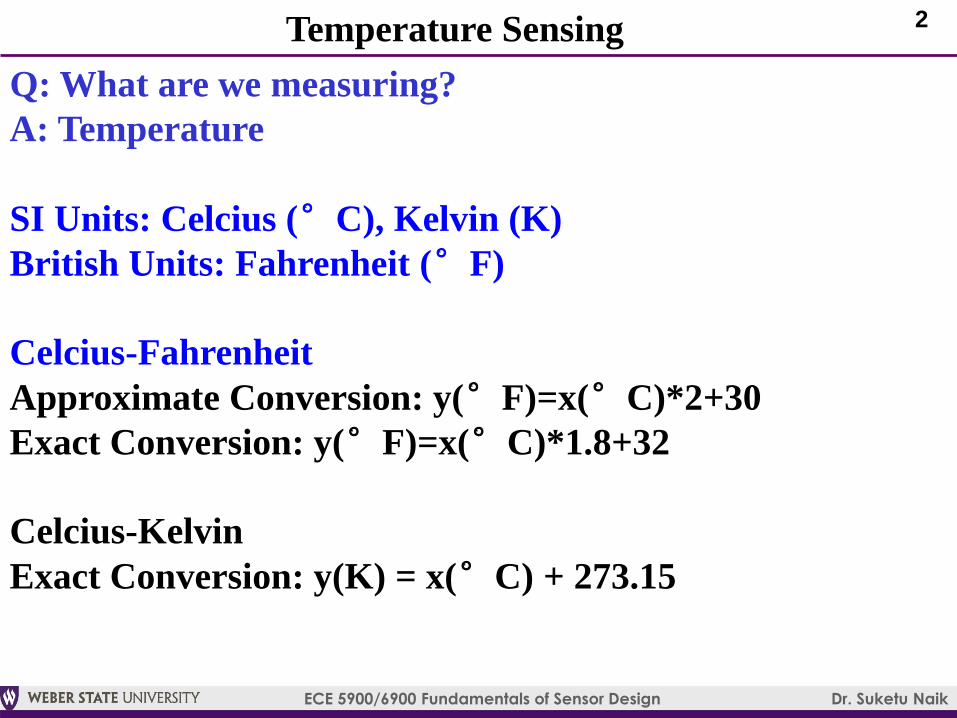
Applications of Temperature Sensors
Gas Oven Safety
Valve
(Thermocouple)
Oil Refinery
(Thermocouple)

6
ECE 5900/6900 Fundamentals of Sensor Design Dr. Suketu Naik
Types of Temperature Sensors
Resistance Temperature Detector (RTD)
NTC Thermistor
Thermocouple

7
ECE 5900/6900 Fundamentals of Sensor Design Dr. Suketu Naik
Resistance Temperature Detector (RTD) Sensors
Thin film RTD
Thin Film RTDs are mainly platinum on Si substrate
Platinum (Pt-RTD) exhibits a nearly linear temperature-
resistance curve
High stability, repeatability, and accuracy: good for extreme
temperature conditions
Pt-RTD can be used between -50°C and +500°CRef: http://www.ussensor.com/thin-film-platinum-rtds, http://www.pyromation.com/Downloads/Doc/Training_RTD_Theory.pdf

8
ECE 5900/6900 Fundamentals of Sensor Design Dr. Suketu Naik
Resistance Temperature Detector (RTD) Sensors
Wire-wound RTD
Wire-wound RTDs contain Platinum wire wound on glass inside
ceramic or glass tube
More expensive than thin film RTDs
Higher source currents
Positive Temperature Coefficient: resistance increases with an
increase in temperature. Typical PTC= .00385 /deg. C
Typical resistance=100-300 ohms between -100°C and 400°CRef: http://www.ussensor.com/thin-film-platinum-rtds, http://www.pyromation.com/Downloads/Doc/Training_RTD_Theory.pdf
For both Wire-wound
and thin-film RTDs

9
ECE 5900/6900 Fundamentals of Sensor Design Dr. Suketu Naik
Resistance vs Temperature Curve
Ref: http://archives.sensorsmag.com/articles/0503/52/main.shtml
-200°C to 0°C: )]100(1[ 32 tCtBtAtRR Ot
0 °C to 630°C: ]1[ 2BtAtRR Ot
Stable, Linear
Response of
Platinum (Pt)

10
ECE 5900/6900 Fundamentals of Sensor Design Dr. Suketu Naik
Types of Temperature Sensors
Resistance Temperature Detector (RTD)
NTC Thermistor
Thermocouple

11
ECE 5900/6900 Fundamentals of Sensor Design Dr. Suketu Naik
ThermistorThermistor=thermal + resistor
Thermistor changes its resistance with change in temperature
RTD are usually made from metals, thermistors can be ceramic
or polymer based
RTDs have wide temperature range, thermistors have limited
temperature range
Negative Temperature Coefficient (NTC): resistance decreases
with increasing temperature
12
ECE 5900/6900 Fundamentals of Sensor Design Dr. Suketu Naik
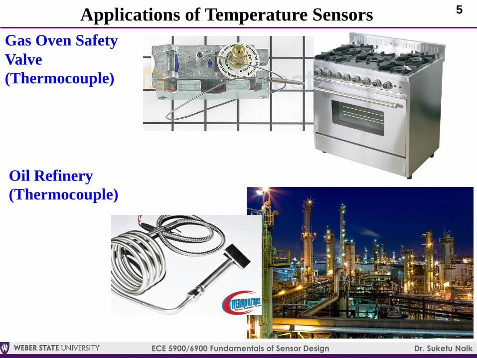
Thermistor Transfer Function
Stable, Linear
Response of
Platinum (Pt)Resistance of
thermistor at
25 °C
Assume negligible self-heating (negligible rise in its temperature
when the current is passing through the thermistor)

13
ECE 5900/6900 Fundamentals of Sensor Design Dr. Suketu Naik
Thermistor Model
Basic Equation
3
3
2
210ln
T
A
T
A
T
AAS
where S=measured resitance of a thermistor at the unknown temperature
T, and A0, A1, A2, A3 are constants derived empirically
Simple Model (first order approximation) 1
0
11
0
ln1
ln 0
m
oTTm S
S
TTeSS
TAS
m
where βm=material characteristic temperature (K), To=reference
temperature (~25 °C), So=reference resistance
Modified Steinhart-Hart Model (Vishay Spreadsheet)
13
0
2
00
lnlnln
R
RD
R
RC
R
RBAT
where
A,B,C,D=empirical
constants (given)
Ro=reference resistance
R= measured resistance

14
ECE 5900/6900 Fundamentals of Sensor Design Dr. Suketu Naik
Thermistor Circuit
Wheatstone Bridge with Instrumentation Amplifier
Thermistor
Quarter Bridge INA126
+
Vo1
-
+
Vo2
-
Match R1=R2=R3=R=R0=resistance of thermistor at 25°C
First figure out Vo1 in relation to the resistance ratio, R4/R
Use relation Vo2=GVo1 (where G= gain of the INA=>look up in the
datsheet or derive from the measured data) and solve for unknown
temperature T

15
ECE 5900/6900 Fundamentals of Sensor Design Dr. Suketu Naik
Types of Temperature Sensors
Resistance Temperature Detector (RTD)
NTC Thermistor
Thermocouple

16
ECE 5900/6900 Fundamentals of Sensor Design Dr. Suketu Naik
Type K (Chromel-Alumel) Thermocouple
Thermocouple
Amplifier
Thermocouple
Junction
Ref: Thermocouple application by Texas Instruments

17
ECE 5900/6900 Fundamentals of Sensor Design Dr. Suketu Naik
Thermocouple SensorsThermocouple (or Thermoelectric) Sensor
Thermocouple junction is formed when to dissimilar metals or
metal alloys are joined together (often the leads are also made of
dissimilar metals
Thermocouple junction put in contact with the hot or cold point
and the leads are kept at room temperature
The temperature gradient is developed along the length of the
leads which results in two separate Seebeck EMFsRef: Thermocouple application by Texas Instruments
No voltage is developed at the
thermocouple junction!

18
ECE 5900/6900 Fundamentals of Sensor Design Dr. Suketu Naik
Thermoelectric (Seebeck) Effect
When one end of the conductor is hotter than the other end, electrons at
the hot end are thermally energized and diffuse toward the cooler end
N-type: Diffusion of electrons creates positive charge at hot end and
negative charge (abundance of electrons) at the cool end
As a result potential difference or thermocouple EMF is generated
These
can also
be two
different
metals
Thermoelectric Circuit

19
ECE 5900/6900 Fundamentals of Sensor Design Dr. Suketu Naik
Seebeck Coefficients
Possible wire pairings:
Type J(T): Iron(copper) for the positive terminal and constantan for
the negative terminal
Most Common is Type K Type K: Chromel-Alumel
Chromel: 90% Ni, 10% Cr
Alumel: 95% Ni, 2% Mn, 2% Al and 1% SiRef: Thermocouple application by Texas Instruments

20
ECE 5900/6900 Fundamentals of Sensor Design Dr. Suketu Naik
Thermocouple: Voltage to Temperature Curves
p
p
rx
VTT
; where, Tx= unknown temperature, Tr=reference temerpature,
Vp=thermocouple emf, αp=thermocouple sensitivity [μV/°C]