Embed Size (px)
Citation preview
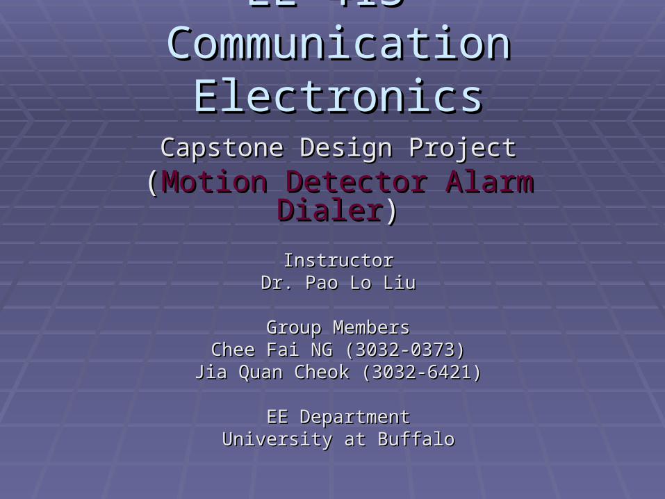
EE 413 EE 413 Communication ElectronicsCommunication Electronics
Capstone Design ProjectCapstone Design Project
((Motion Detector Alarm DialerMotion Detector Alarm Dialer))
InstructorInstructorDr. Pao Lo LiuDr. Pao Lo Liu
Group MembersGroup MembersChee Fai NG (3032-0373)Chee Fai NG (3032-0373)
Jia Quan Cheok (3032-6421)Jia Quan Cheok (3032-6421)
EE DepartmentEE DepartmentUniversity at BuffaloUniversity at Buffalo
Project Title: Automatic Dial Alarm Project Title: Automatic Dial Alarm SystemSystem
Objectives:-Objectives:- To design and build application circuits using To design and build application circuits using
microcontroller.microcontroller. To understand how a dial alarm system work.To understand how a dial alarm system work. To build a motion detector and understand To build a motion detector and understand
how it work.how it work. To learn and understand PIC language which To learn and understand PIC language which
use to program the microcontroller. use to program the microcontroller.
How The Dial Alarm Circuit WorkHow The Dial Alarm Circuit Work
This dial alarm system consists of motion This dial alarm system consists of motion detector as an input. detector as an input.
A trigger pulse will send by the motion A trigger pulse will send by the motion detector once it sense any movement detector once it sense any movement occurs within the coverage area. occurs within the coverage area.
This trigger pulse will turn on a BC 557 This trigger pulse will turn on a BC 557 transistor and deliver power to transistor and deliver power to microcontroller.microcontroller.
Microcontroller will then start to execute Microcontroller will then start to execute the program. the program.
How The Dial Alarm Circuit Work How The Dial Alarm Circuit Work (Cont.)(Cont.)
The LED in the opto-coupler will be turns on and The LED in the opto-coupler will be turns on and causes the line to be “picked up” by using a high causes the line to be “picked up” by using a high gain Darlington transistor. gain Darlington transistor.
The microcontroller then dials two pre set phone The microcontroller then dials two pre set phone numbers to alert the listener by sent down a numbers to alert the listener by sent down a “Hee Haw” signal. “Hee Haw” signal.
A microphone with high gain amplifier also A microphone with high gain amplifier also connected to the phone line to detect connected to the phone line to detect conversation or movement in the target area. conversation or movement in the target area.
The two numbers are then called again before The two numbers are then called again before the alarm closes down. the alarm closes down.
Dial Alarm Circuit Dial Alarm Circuit
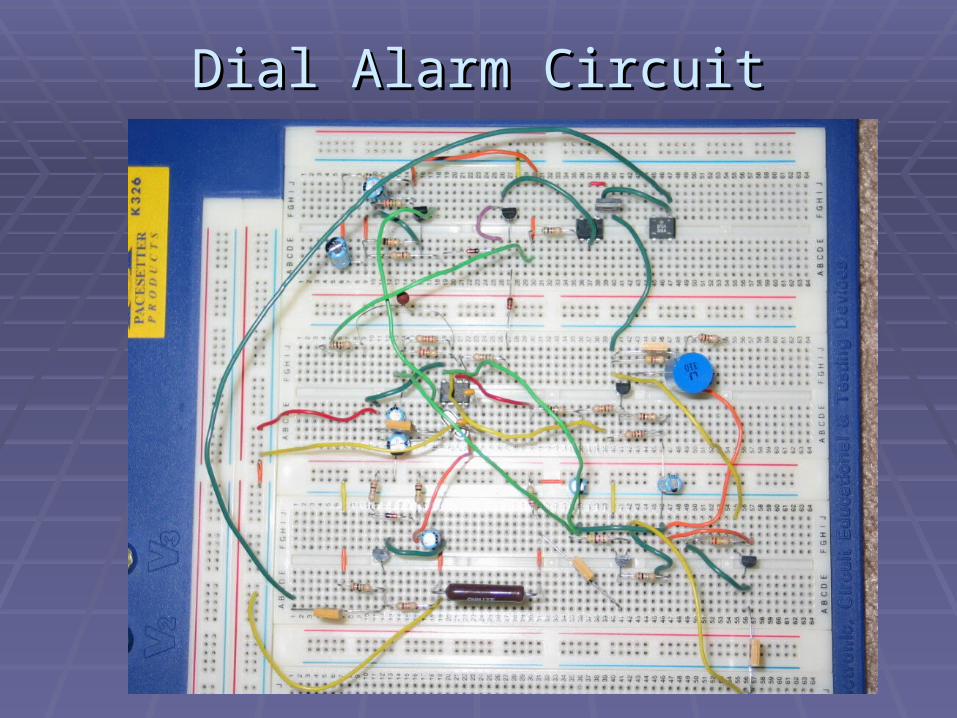
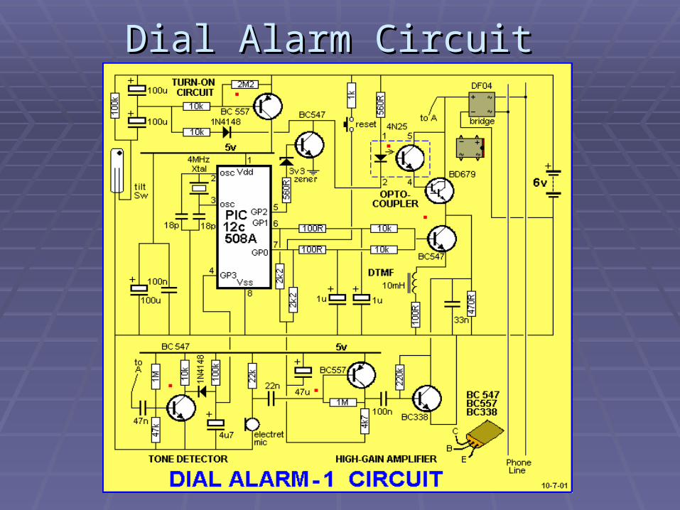
Dial Alarm CircuitDial Alarm Circuit
Dial Alarm Circuit (Cont.)Dial Alarm Circuit (Cont.)
Turn on circuitTurn on circuit Tone detectorTone detector DTMF wave shaping circuitDTMF wave shaping circuit High gain audio amplifierHigh gain audio amplifier Opto-coupler Opto-coupler MicrocontrollerMicrocontroller
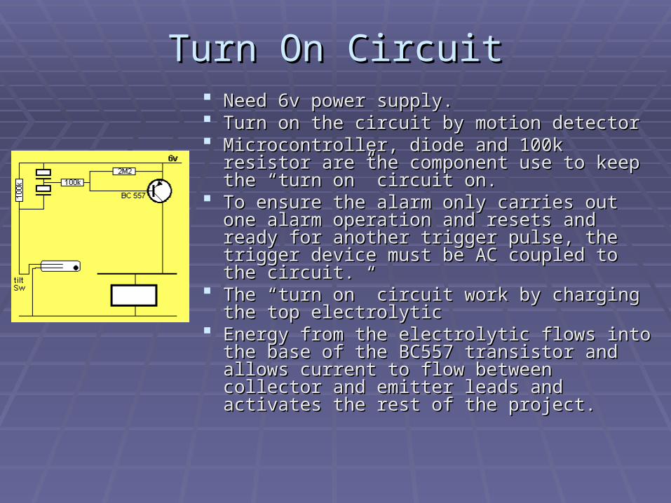
Turn On CircuitTurn On Circuit Need 6v power supply. Need 6v power supply. Turn on the circuit by motion detector Turn on the circuit by motion detector Microcontroller, diode and 100k resistor are Microcontroller, diode and 100k resistor are
the component use to keep the “turn on” the component use to keep the “turn on” circuit on. circuit on.
To ensure the alarm only carries out one To ensure the alarm only carries out one alarm operation and resets and ready for alarm operation and resets and ready for another trigger pulse, the trigger device must another trigger pulse, the trigger device must be AC coupled to the circuit. be AC coupled to the circuit.
The “turn on” circuit work by charging the top The “turn on” circuit work by charging the top electrolytic electrolytic
Energy from the electrolytic flows into the Energy from the electrolytic flows into the base of the BC557 transistor and allows base of the BC557 transistor and allows current to flow between collector and emitter current to flow between collector and emitter leads and activates the rest of the project. leads and activates the rest of the project.
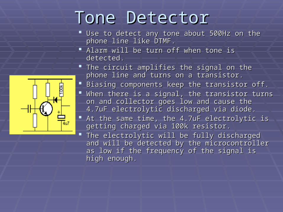
Tone DetectorTone Detector Use to detect any tone about 500Hz on the Use to detect any tone about 500Hz on the
phone line like DTMF. phone line like DTMF. Alarm will be turn off when tone is detected. Alarm will be turn off when tone is detected. The circuit amplifies the signal on the phone line The circuit amplifies the signal on the phone line
and turns on a transistor. and turns on a transistor. Biasing components keep the transistor off. Biasing components keep the transistor off. When there is a signal, the transistor turns on When there is a signal, the transistor turns on
and collector goes low and cause the 4.7uF and collector goes low and cause the 4.7uF electrolytic discharged via diode. electrolytic discharged via diode.
At the same time, the 4.7uF electrolytic is At the same time, the 4.7uF electrolytic is getting charged via 100k resistor. getting charged via 100k resistor.
The electrolytic will be fully discharged and will The electrolytic will be fully discharged and will be detected by the microcontroller as low if the be detected by the microcontroller as low if the frequency of the signal is high enough. frequency of the signal is high enough.
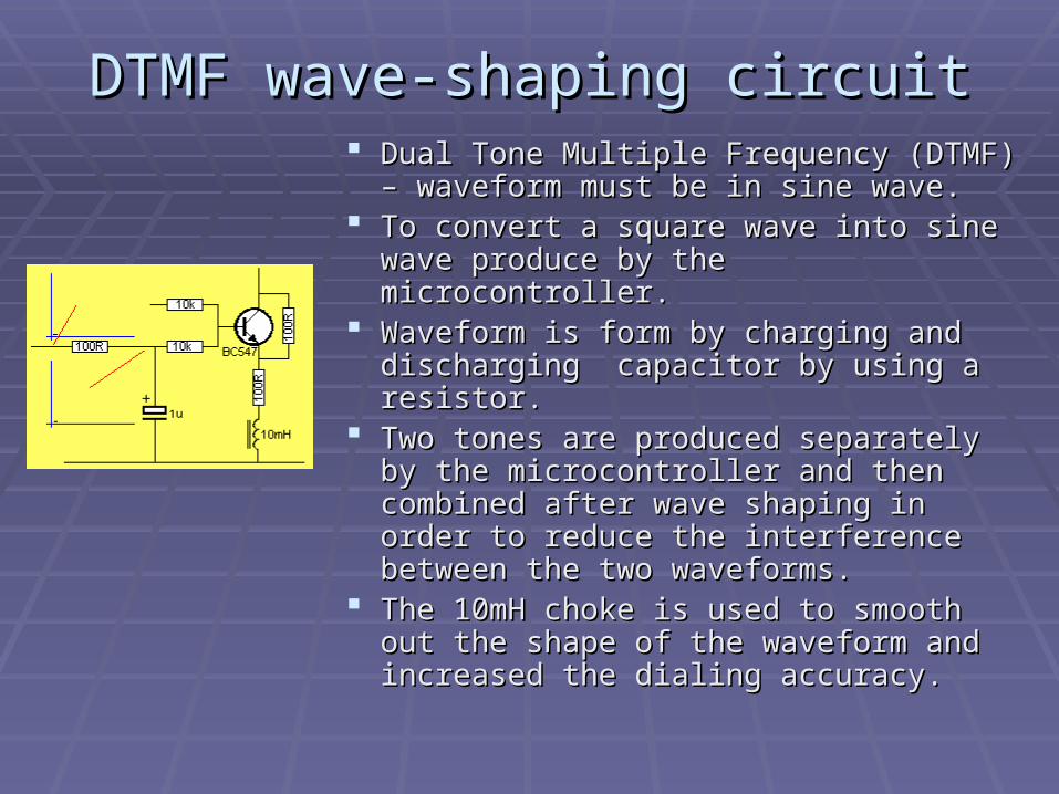
DTMF wave-shaping circuitDTMF wave-shaping circuit Dual Tone Multiple Frequency (DTMF) – Dual Tone Multiple Frequency (DTMF) –
waveform must be in sine wave. waveform must be in sine wave. To convert a square wave into sine wave To convert a square wave into sine wave
produce by the microcontroller. produce by the microcontroller. Waveform is form by charging and Waveform is form by charging and
discharging capacitor by using a resistor. discharging capacitor by using a resistor. Two tones are produced separately by the Two tones are produced separately by the
microcontroller and then combined after microcontroller and then combined after wave shaping in order to reduce the wave shaping in order to reduce the interference between the two waveforms. interference between the two waveforms.
The 10mH choke is used to smooth out The 10mH choke is used to smooth out the shape of the waveform and increased the shape of the waveform and increased the dialing accuracy. the dialing accuracy.
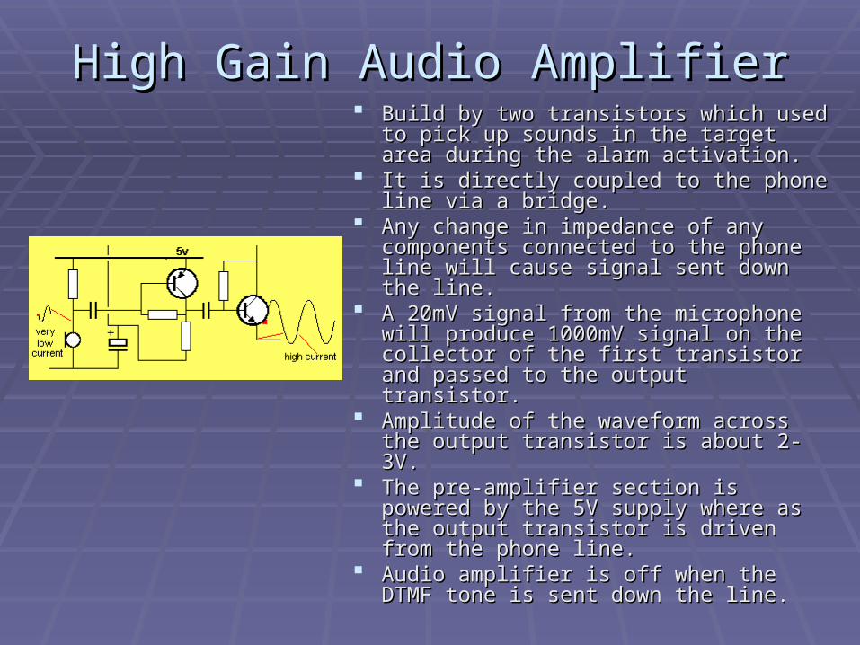
High Gain Audio AmplifierHigh Gain Audio Amplifier Build by two transistors which used to pick Build by two transistors which used to pick
up sounds in the target area during the up sounds in the target area during the alarm activation. alarm activation.
It is directly coupled to the phone line via a It is directly coupled to the phone line via a bridge. bridge.
Any change in impedance of any Any change in impedance of any components connected to the phone line components connected to the phone line will cause signal sent down the line. will cause signal sent down the line.
A 20mV signal from the microphone will A 20mV signal from the microphone will produce 1000mV signal on the collector of produce 1000mV signal on the collector of the first transistor and passed to the the first transistor and passed to the output transistor. output transistor.
Amplitude of the waveform across the Amplitude of the waveform across the output transistor is about 2-3V. output transistor is about 2-3V.
The pre-amplifier section is powered by The pre-amplifier section is powered by the 5V supply where as the output the 5V supply where as the output transistor is driven from the phone line. transistor is driven from the phone line.
Audio amplifier is off when the DTMF tone Audio amplifier is off when the DTMF tone is sent down the line.is sent down the line.
Opto-couplerOpto-coupler
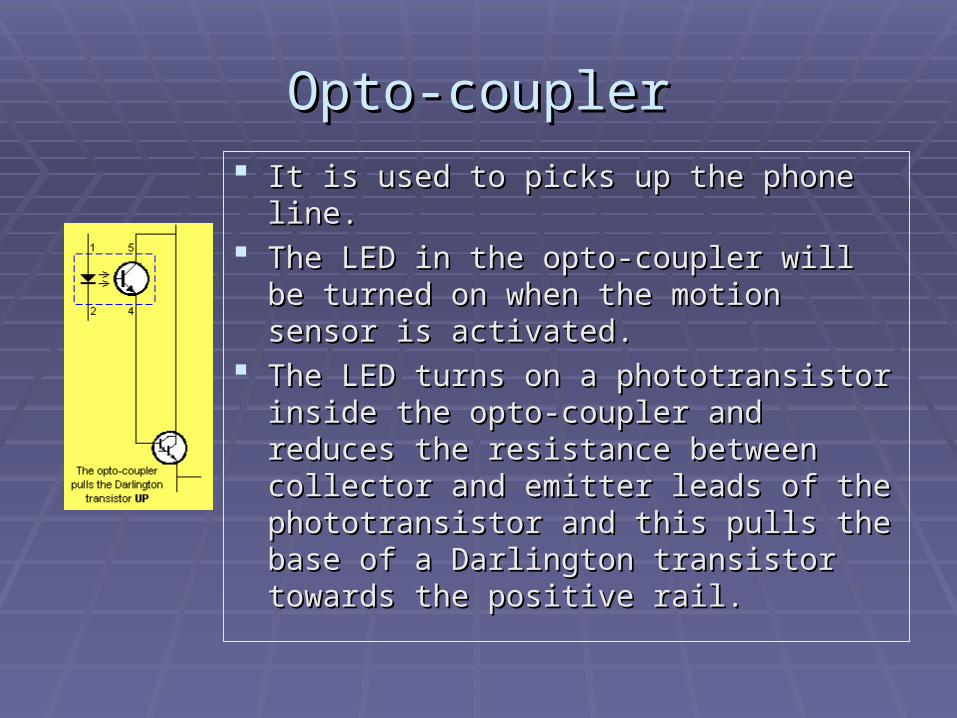
It is used to picks up the phone line. It is used to picks up the phone line. The LED in the opto-coupler will be turned The LED in the opto-coupler will be turned
on when the motion sensor is activated. on when the motion sensor is activated. The LED turns on a phototransistor inside The LED turns on a phototransistor inside
the opto-coupler and reduces the resistance the opto-coupler and reduces the resistance between collector and emitter leads of the between collector and emitter leads of the phototransistor and this pulls the base of a phototransistor and this pulls the base of a Darlington transistor towards the positive Darlington transistor towards the positive rail.rail.
MicrocontrollerMicrocontroller
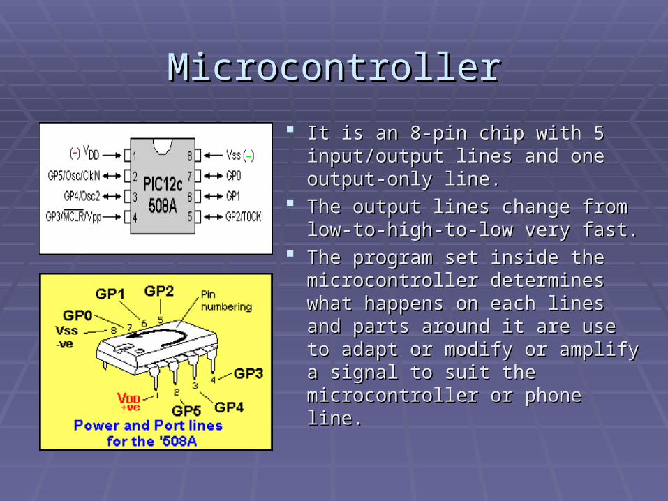
It is an 8-pin chip with 5 It is an 8-pin chip with 5 input/output lines and one output-input/output lines and one output-only line. only line.
The output lines change from The output lines change from low-to-high-to-low very fast. low-to-high-to-low very fast.
The program set inside the The program set inside the microcontroller determines what microcontroller determines what happens on each lines and parts happens on each lines and parts around it are use to adapt or around it are use to adapt or modify or amplify a signal to suit modify or amplify a signal to suit the microcontroller or phone line. the microcontroller or phone line.
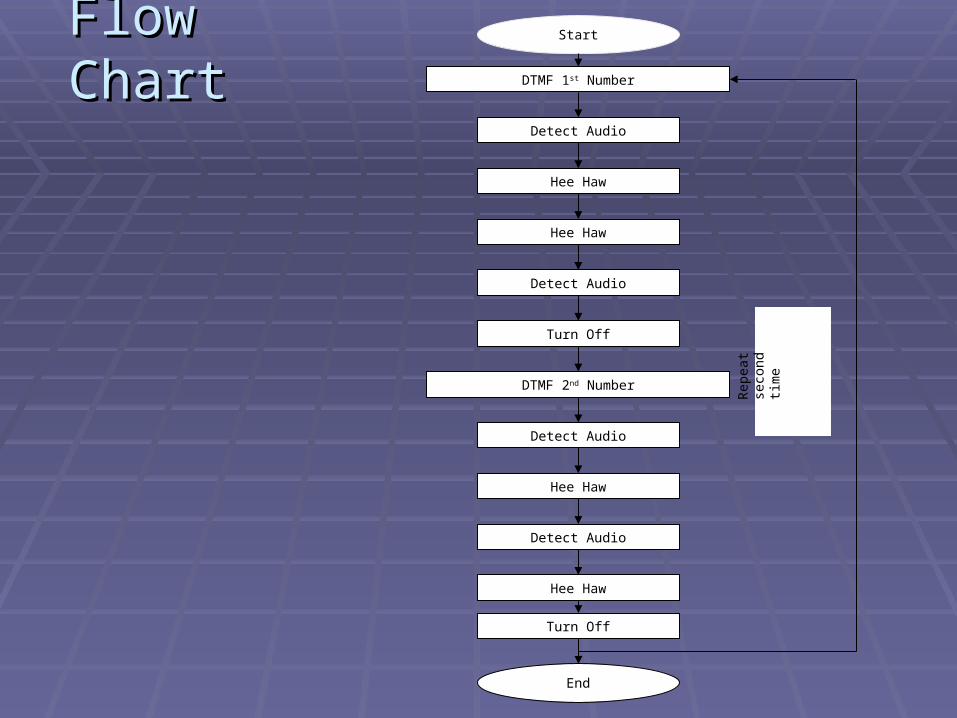
Flow ChartFlow Chart
Turn Off
DTMF 2nd Number
Turn Off
DTMF 1st Number
Detect Audio
Detect Audio
Hee Haw
Hee Haw
Detect Audio
Hee Haw
Detect Audio
Start
End
Hee Haw
Rep
eat
seco
nd
time
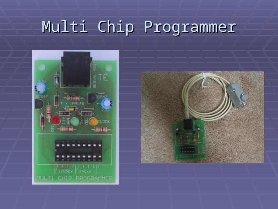
Multi Chip ProgrammerMulti Chip Programmer
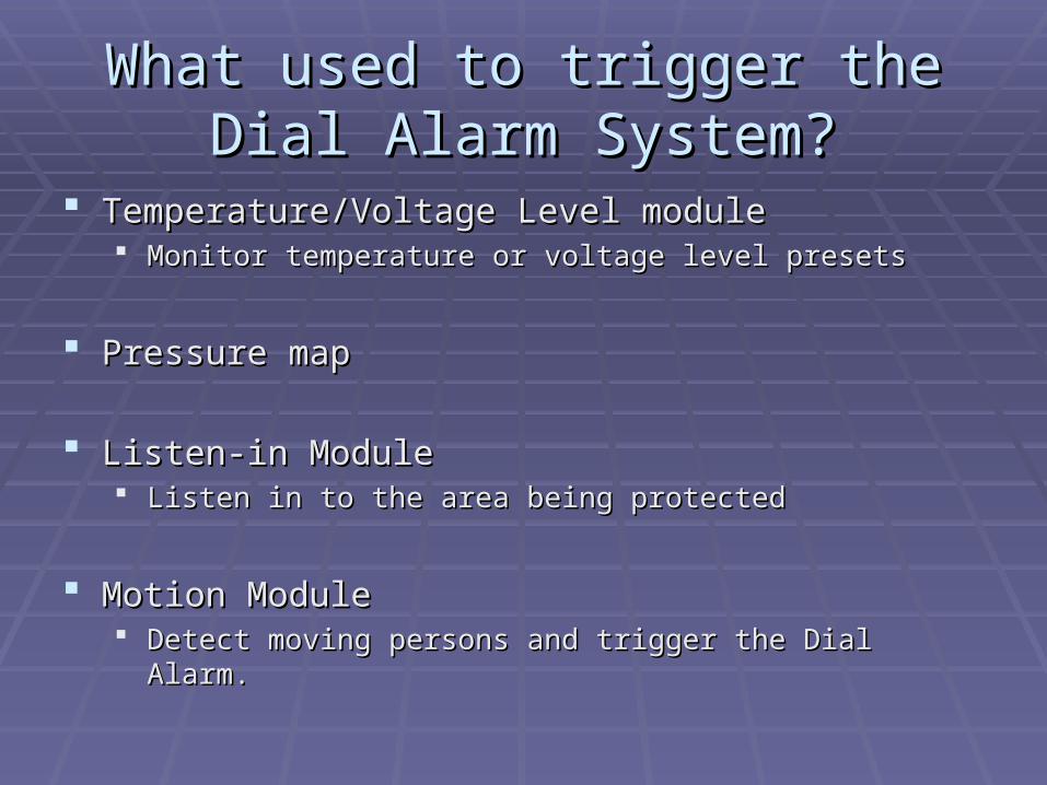
What used to trigger the Dial Alarm What used to trigger the Dial Alarm System?System?
Temperature/Voltage Level moduleTemperature/Voltage Level module Monitor temperature or voltage level presetsMonitor temperature or voltage level presets
Pressure mapPressure map
Listen-in ModuleListen-in Module Listen in to the area being protected Listen in to the area being protected
Motion ModuleMotion Module Detect moving persons and trigger the Dial Alarm.Detect moving persons and trigger the Dial Alarm.
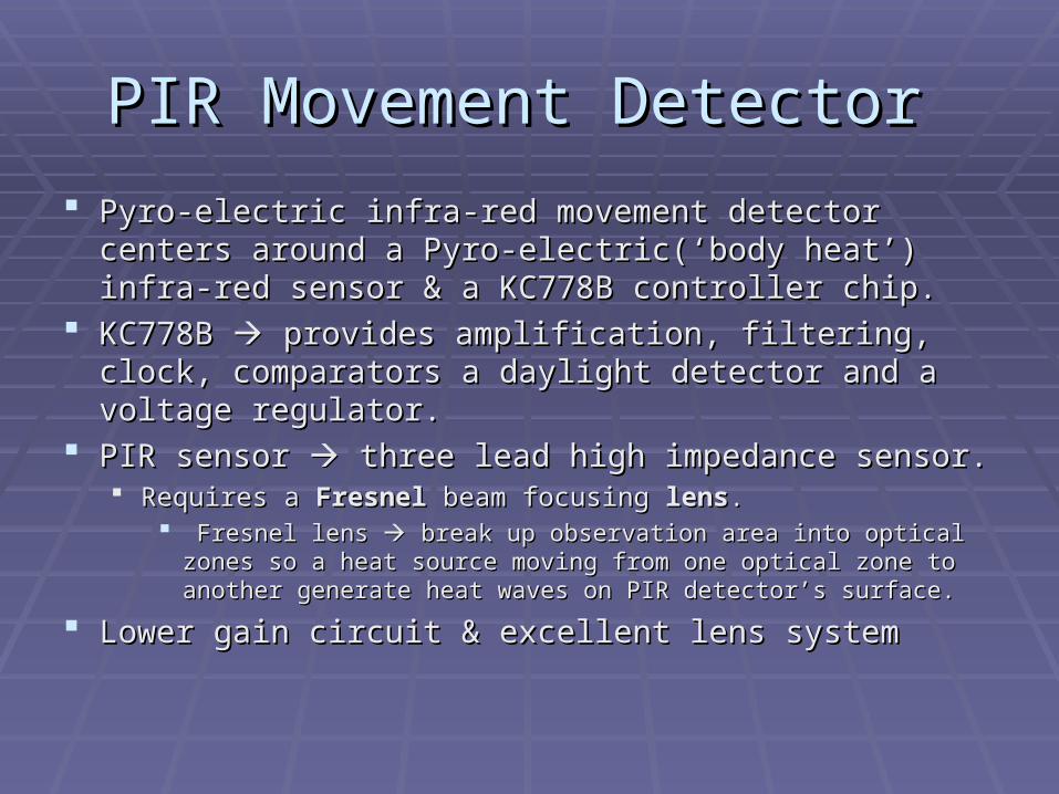
PIR Movement DetectorPIR Movement Detector
Pyro-electric infra-red movement detector centers Pyro-electric infra-red movement detector centers around a Pyro-electric(‘body heat’) infra-red sensor & a around a Pyro-electric(‘body heat’) infra-red sensor & a KC778B controller chip.KC778B controller chip.
KC778B KC778B provides amplification, filtering, clock, provides amplification, filtering, clock, comparators a daylight detector and a voltage regulator.comparators a daylight detector and a voltage regulator.
PIR sensor PIR sensor three lead high impedance sensor. three lead high impedance sensor. Requires a Requires a FresnelFresnel beam focusing beam focusing lenslens..
Fresnel lens Fresnel lens break up observation area into optical zones so a break up observation area into optical zones so a heat source moving from one optical zone to another generate heat heat source moving from one optical zone to another generate heat waves on PIR detector’s surface.waves on PIR detector’s surface.
Lower gain circuit & excellent lens systemLower gain circuit & excellent lens system
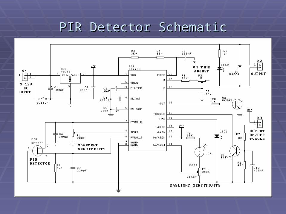
PIR Detector SchematicPIR Detector Schematic
Circuit DescriptionCircuit Description There are three main sensitivity There are three main sensitivity
controls built into circuit:-controls built into circuit:-
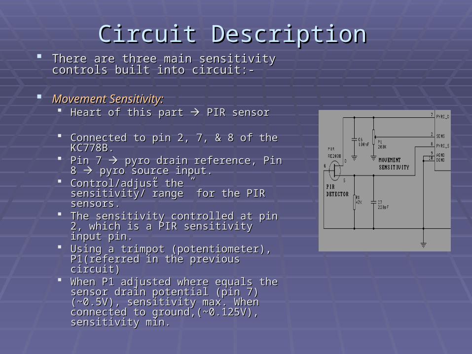
Movement Sensitivity:Movement Sensitivity: Heart of this part Heart of this part PIR sensor PIR sensor
Connected to pin 2, 7, & 8 of the Connected to pin 2, 7, & 8 of the KC778B. KC778B.
Pin 7 Pin 7 pyro drain reference, Pin 8 pyro drain reference, Pin 8 pyro source input.pyro source input.
Control/adjust the sensitivity/”range” for Control/adjust the sensitivity/”range” for the PIR sensors.the PIR sensors.
The sensitivity controlled at pin 2, which The sensitivity controlled at pin 2, which is a PIR sensitivity input pin.is a PIR sensitivity input pin.
Using a trimpot (potentiometer), Using a trimpot (potentiometer), P1(referred in the previous circuit)P1(referred in the previous circuit)
When P1 adjusted where equals the When P1 adjusted where equals the sensor drain potential (pin 7) (~0.5V), sensor drain potential (pin 7) (~0.5V), sensitivity max. When connected to sensitivity max. When connected to ground,(~0.125V), sensitivity min.ground,(~0.125V), sensitivity min.
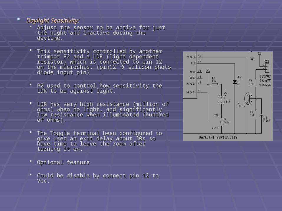
Daylight Sensitivity:Daylight Sensitivity: Adjust the sensor to be active for just the night Adjust the sensor to be active for just the night
and inactive during the daytime.and inactive during the daytime.
This sensitivity controlled by another trimpot P2 This sensitivity controlled by another trimpot P2 and a LDR (light dependent resistor) which is and a LDR (light dependent resistor) which is connected to pin 12 on the microchip. (pin12 connected to pin 12 on the microchip. (pin12 silicon photo diode input pin)silicon photo diode input pin)
P2 used to control how sensitivity the LDR to P2 used to control how sensitivity the LDR to be against light.be against light.
LDR has very high resistance (million of ohms) LDR has very high resistance (million of ohms) when no light, and significantly low resistance when no light, and significantly low resistance when illuminated (hundred of ohms).when illuminated (hundred of ohms).
The Toggle terminal been configured to give The Toggle terminal been configured to give user an exit delay about 30s so have time to user an exit delay about 30s so have time to leave the room after turning it on.leave the room after turning it on.
Optional featureOptional feature
Could be disable by connect pin 12 to Vcc.Could be disable by connect pin 12 to Vcc.
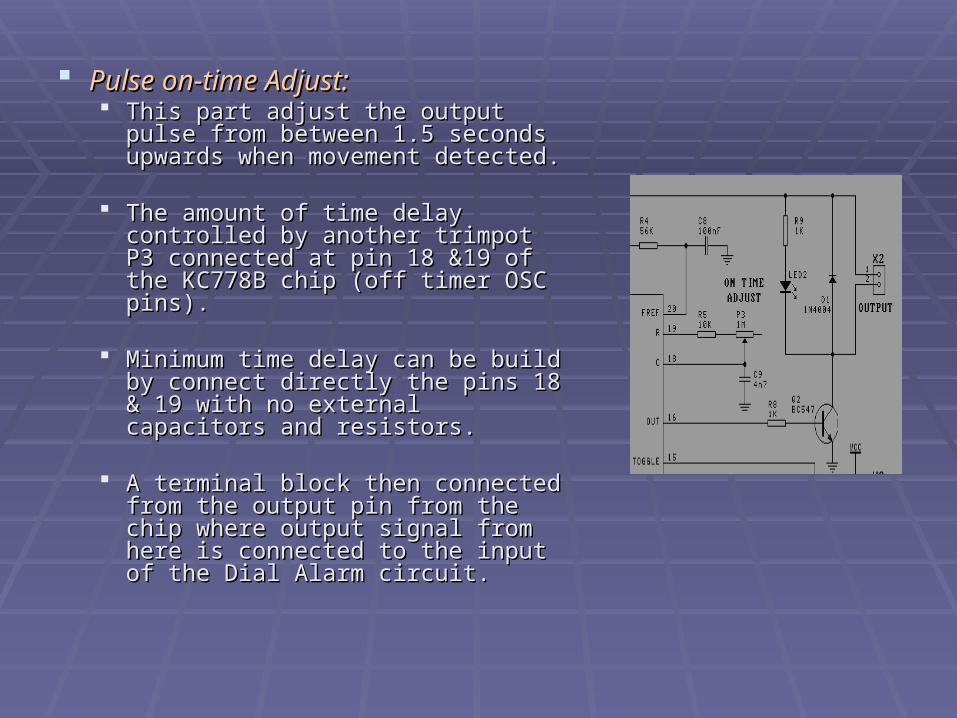
Pulse on-time Adjust:Pulse on-time Adjust: This part adjust the output pulse This part adjust the output pulse
from between 1.5 seconds upwards from between 1.5 seconds upwards when movement detected.when movement detected.
The amount of time delay controlled The amount of time delay controlled by another trimpot P3 connected at by another trimpot P3 connected at pin 18 &19 of the KC778B chip (off pin 18 &19 of the KC778B chip (off timer OSC pins).timer OSC pins).
Minimum time delay can be build by Minimum time delay can be build by connect directly the pins 18 & 19 connect directly the pins 18 & 19 with no external capacitors and with no external capacitors and resistors.resistors.
A terminal block then connected A terminal block then connected from the output pin from the chip from the output pin from the chip where output signal from here is where output signal from here is connected to the input of the Dial connected to the input of the Dial Alarm circuit.Alarm circuit.

KC 778B Controller ChipKC 778B Controller Chip
PIR Front End Amplifiers & Noise cancellation circuit
Switched capacitorBandpass Filter
Oscillator &Synchronization Citcuitry
Threshold comparators & Timing circuitry
Daylight Detector Amplifier and Comparator
Voltage Regulator
Sensitivity Adj
Offset Filter
Pyro (D)Pyro
(S)Gain Select Anti AliasDC Cap
Fref
R
C
Daylight Sense
Daylight Adjust
LED
OUTPUT
V Reg
KC 778B Controller Chip (Cont’d)KC 778B Controller Chip (Cont’d)
The heart of the whole circuit as the motion detection IC.The heart of the whole circuit as the motion detection IC.
Optimum with the electrical signals from the PIR sensors Optimum with the electrical signals from the PIR sensors which have very low frequency (0.1 to 10 Hz) and which have very low frequency (0.1 to 10 Hz) and bandwidth.bandwidth.
Operating voltage is 4 – 15V.Operating voltage is 4 – 15V.
With the 78L05 voltage regulator we connected in pin With the 78L05 voltage regulator we connected in pin 1(Vcc), the input voltage should be around 9 – 12V.1(Vcc), the input voltage should be around 9 – 12V.
PIR Movement Detector (building and PIR Movement Detector (building and testing)testing)
When building up the system, we used ~2.5” by 3.5” PC When building up the system, we used ~2.5” by 3.5” PC Board.Board.
Be aware of the right polarity of capacitors, transistor, Be aware of the right polarity of capacitors, transistor, LEDs and the PIR sensors.LEDs and the PIR sensors.
Components especially the controller chip and PIR Components especially the controller chip and PIR sensor could damaged easily it placed incorrectly.sensor could damaged easily it placed incorrectly.
The PIR sensor, LDR and Fresnel lens are mounted on The PIR sensor, LDR and Fresnel lens are mounted on the copper side of PCB (opposite side of all components)the copper side of PCB (opposite side of all components)
So, the system be easily placed (e.g. in a box) with the So, the system be easily placed (e.g. in a box) with the lens poking out with the electronics on top of the PCB for lens poking out with the electronics on top of the PCB for easy access.easy access.
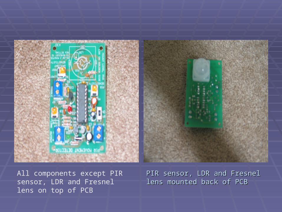
All components except PIR sensor, LDR and Fresnel lens on top of PCB
PIR sensor, LDR and Fresnel lens PIR sensor, LDR and Fresnel lens mounted back of PCBmounted back of PCB
After building the whole circuit, we tested it in the After building the whole circuit, we tested it in the electronics lab.electronics lab.
We applied a 9V transistor battery to Vcc pin of We applied a 9V transistor battery to Vcc pin of the chip.the chip.
Connect a voltmeter to the Output pin.Connect a voltmeter to the Output pin. When power applied, waited about 30 seconds When power applied, waited about 30 seconds
and wave hand in front of PIR sensor.and wave hand in front of PIR sensor. The LED indicator light, and the Voltmeter from The LED indicator light, and the Voltmeter from
the output jump from zero volts to 9 volts in the the output jump from zero volts to 9 volts in the screen.screen.
When no movement detected, the LED light off When no movement detected, the LED light off and the voltmeter value back to zero.and the voltmeter value back to zero.
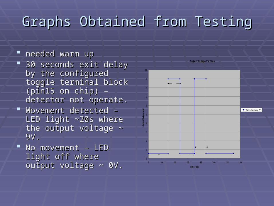
Graphs Obtained from TestingGraphs Obtained from Testing
needed warm upneeded warm up 30 seconds exit delay by 30 seconds exit delay by
the configured toggle the configured toggle terminal block (pin15 on terminal block (pin15 on chip) – detector not chip) – detector not operate.operate.
Movement detected – Movement detected – LED light ~20s where the LED light ~20s where the output voltage ~ 9V.output voltage ~ 9V.
No movement – LED light No movement – LED light off where output voltage off where output voltage ~ 0V.~ 0V.
Output Voltage Vs Time
0
1
2
3
4
5
6
7
8
9
10
0 20 40 60 80 100 120 140
Time, t(s)
Out
put V
olta
ge, V
(V)
Output Volatge (V)
Warm up
On
Off
18s
22s
0.57V
9V
Question???Question???
Finally the PIR movement detector ready Finally the PIR movement detector ready to be cascade to the Dial Alarm circuit!to be cascade to the Dial Alarm circuit!
Became a Became a Motion Detector Alarm DialerMotion Detector Alarm Dialer!!