Embed Size (px)
Citation preview

EE 230Lecture 13
Basic Applications of Operational AmplifiersAnalog ComputationCoupling of Building BlocksDifferential Amplifiers
Nonideal Op Amp Characteristics (if time permits)

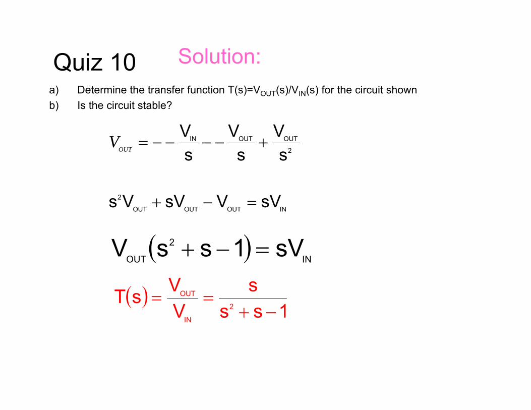
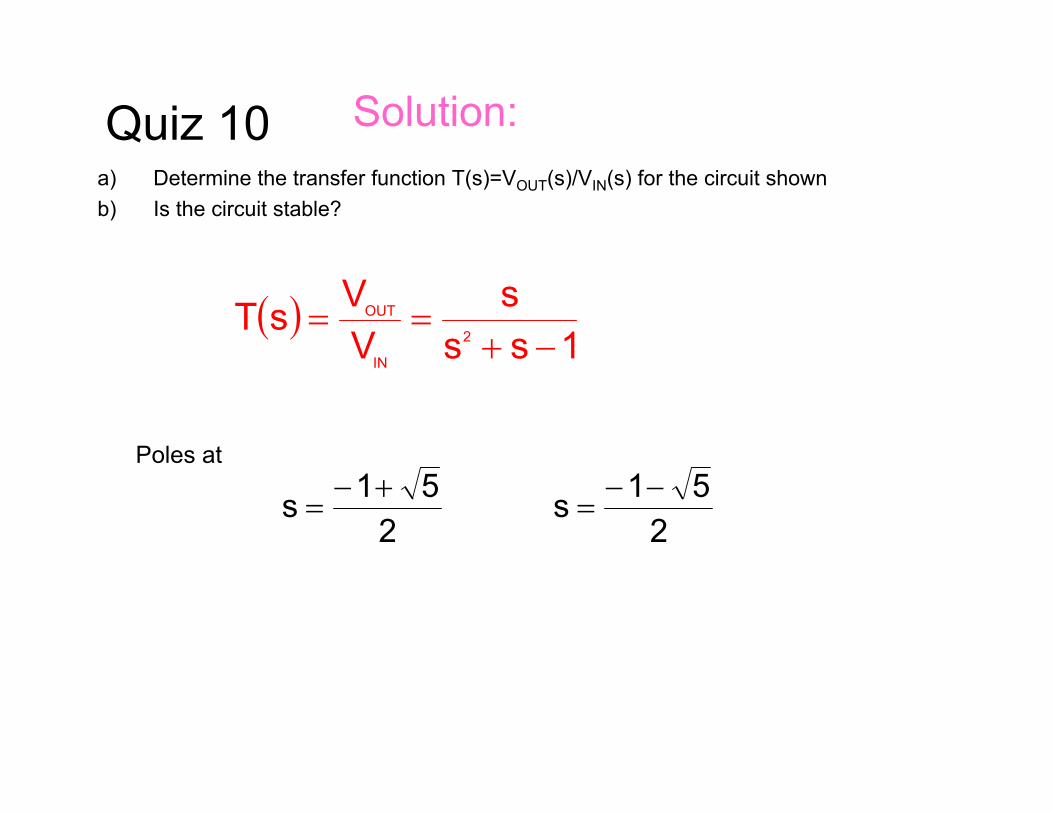
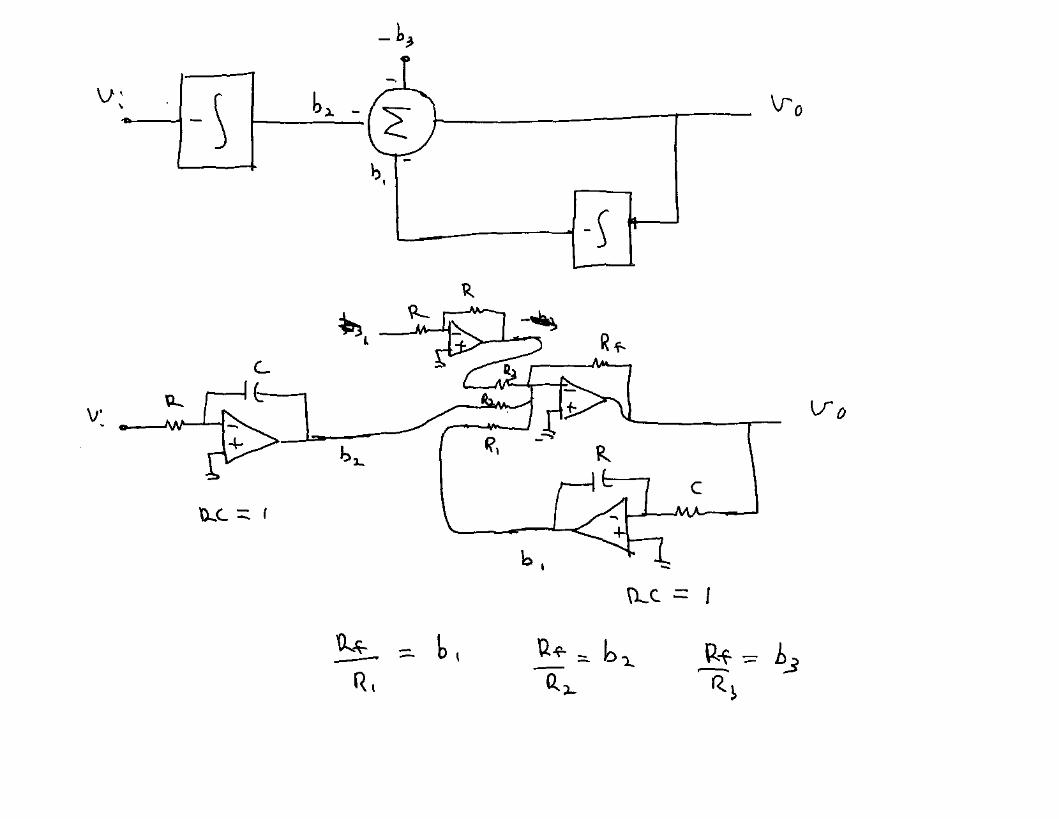
Quiz 10a) Determine the transfer function T(s)=VOUT(s)/VIN(s) for the
circuit shownb) Is the circuit stable?Assume the op amps are ideal and all resistors are 1Ω and all
capacitors are 1F

And the number is ?
1 3 8
4
67
5
29

And the number is ?
1 3 8
4
67
5
29

Quiz 10a) Determine the transfer function T(s)=VOUT(s)/VIN(s) for the circuit shownb) Is the circuit stable?
Solution:

Quiz 10a) Determine the transfer function T(s)=VOUT(s)/VIN(s) for the circuit shownb) Is the circuit stable?
Solution:

Quiz 10a) Determine the transfer function T(s)=VOUT(s)/VIN(s) for the circuit shownb) Is the circuit stable?
Solution:
sVOUT−2
OUT
sV
sVIN−

Quiz 10a) Determine the transfer function T(s)=VOUT(s)/VIN(s) for the circuit shownb) Is the circuit stable?
Solution:
sVOUT−2
OUT
sV
sVIN−
2
OUTOUTIN
sV
sV
sV
+−−−−=OUTV
Quiz 10a) Determine the transfer function T(s)=VOUT(s)/VIN(s) for the circuit shownb) Is the circuit stable?
Solution:
2
OUTOUTIN
sV
sV
sV
+−−−−=OUTV
INOUTOUTOUT
2 sVVsVVs =−+
( ) IN
2
OUT sV1ssV =−+
( )1ss
sVVsT
2
IN
OUT
−+==
Quiz 10a) Determine the transfer function T(s)=VOUT(s)/VIN(s) for the circuit shownb) Is the circuit stable?
Solution:
( )1ss
sVVsT
2
IN
OUT
−+==
Poles at
251s +−
=2
51s −−=

Quiz 10a) Determine the transfer function T(s)=VOUT(s)/VIN(s) for the circuit shownb) Is the circuit stable?
Solution:
( )1ss
sVVsT
2
IN
OUT
−+==
Poles at
251s +−
=2
51s −−=
LHP RHP

Quiz 10a) Determine the transfer function T(s)=VOUT(s)/VIN(s) for the circuit shownb) Is the circuit stable?
Solution:
( )1ss
sVVsT
2
IN
OUT
−+==
Poles at
251s +−
=2
51s −−=
LHP RHP
Since there is one RHP pole, the circuit is unstable !

Review from Last Time
Integrators:One of the most widely used op amp circuitsSeldom used as open-loop integratorWidely used in feedback applicationsNoninverting integrator circuits require more components
Precede or Follow inverting integrator with inverterUse extra capacitor with pole/zero cancellationSumming integrators require one additional resistor for each input
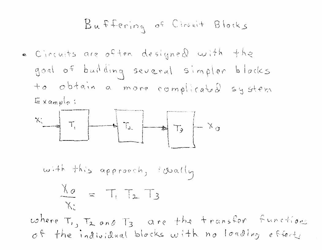
Integrators and SummersUsed to build analog computersCan implement arbitrary transfer functionsMany filters are nothing other than a dedicated analog computer!


The Strain Gage http://www.omega.com/literature/transactions/volume3/strain.html
1 of 6 2/3/2006 6:18 AM
omega.com HOME
A Historical PerspectiveFrom Aristotle to HawkingForce & Its EffectsMeasurement Limitations The Strain GageSensor DesignsMeasuring CircuitsApplication & Installation Process Pressure MeasurementFrom Mechanical to ElectronicTransducer TypesPractical Considerations High Pressure & VacuumHigh Pressure DesignsVery High PressuresVacuum Instrumentation Pressure Gauges & SwitchesPressure Gauge DesignsProtective AccessoriesPressure Switches Force, Acceleration, & TorqueForce SensorsAcceleration & VibrationTorque Measurement Load Cell DesignsOperating PrinciplesNew Sensor DevelopmentsStrain Gage Configurations Weighing ApplicationsWeighing System DesignInstallation & CalibrationSpecialized Installations Information ResourcesGlossaryIndexList of FiguresData Tables Transactions Home
When external forces are applied to a stationary object, stress and strain are the result. Stress is defined as the object's internalresisting forces, and strain is defined as the displacement and deformation that occur. For a uniform distribution of internal resisting forces, stress can be calculated (Figure 2-1) by dividing the force (F) applied by the unit area (A):
Strain is defined as the amount of deformation per unit length ofan object when a load is applied. Strain is calculated by dividing the total deformation of the original length by the original length (L):
Typical values for strain are less than 0.005 inch/inch and areoften expressed in micro-strain units:
Strain may be compressive or tensile and is typically measuredby strain gages. It was Lord Kelvin who first reported in 1856 that metallic conductors subjected to mechanical strain exhibit a change in their electrical resistance. This phenomenon was first put to practical use in the 1930s.
Figure 2-1: Definitions of Stress & Strain
Fundamentally, all strain gages are designed to convertmechanical motion into an electronic signal. A change in capacitance, inductance, or resistance is proportional to the strain experienced by the sensor. If a wire is held under tension, it gets slightly longer and its cross-sectional area is reduced. This changes its resistance (R) in proportion to the strain sensitivity (S) of the wire's resistance. When a strain is introduced, the strain sensitivity, which is also called the gage factor (GF), is given by:
The Strain Gage http://www.omega.com/literature/transactions/volume3/strain.html
2 of 6 2/3/2006 6:18 AM
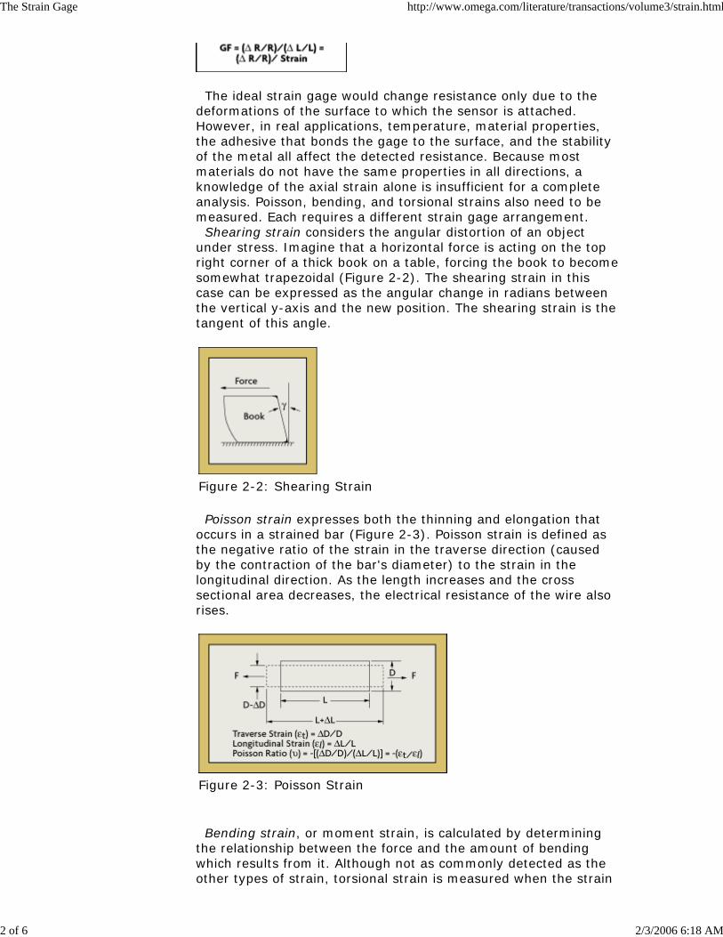
The ideal strain gage would change resistance only due to thedeformations of the surface to which the sensor is attached. However, in real applications, temperature, material properties, the adhesive that bonds the gage to the surface, and the stability of the metal all affect the detected resistance. Because most materials do not have the same properties in all directions, a knowledge of the axial strain alone is insufficient for a complete analysis. Poisson, bending, and torsional strains also need to be measured. Each requires a different strain gage arrangement. Shearing strain considers the angular distortion of an object under stress. Imagine that a horizontal force is acting on the top right corner of a thick book on a table, forcing the book to become somewhat trapezoidal (Figure 2-2). The shearing strain in this case can be expressed as the angular change in radians between the vertical y-axis and the new position. The shearing strain is the tangent of this angle.
Figure 2-2: Shearing Strain
Poisson strain expresses both the thinning and elongation that occurs in a strained bar (Figure 2-3). Poisson strain is defined as the negative ratio of the strain in the traverse direction (caused by the contraction of the bar's diameter) to the strain in the longitudinal direction. As the length increases and the cross sectional area decreases, the electrical resistance of the wire also rises.
Figure 2-3: Poisson Strain
Bending strain, or moment strain, is calculated by determining the relationship between the force and the amount of bending which results from it. Although not as commonly detected as the other types of strain, torsional strain is measured when the strain

The Strain Gage http://www.omega.com/literature/transactions/volume3/strain.html
3 of 6 2/3/2006 6:18 AM
produced by twisting is of interest. Torsional strain is calculated by dividing the torsional stress by the torsional modulus of elasticity.
Sensor DesignsThe deformation of an object can be measured by mechanical,optical, acoustical, pneumatic, and electrical means. The earliest strain gages were mechanical devices that measured strain by measuring the change in length and comparing it to the original length of the object. For example, the extension meter (extensiometer) uses a series of levers to amplify strain to a readable value. In general, however, mechanical devices tend to provide low resolutions, and are bulky and difficult to use.
Figure 2-4: Strain Gage Designs
Optical sensors are sensitive and accurate, but are delicate andnot very popular in industrial applications. They use interference fringes produced by optical flats to measure strain. Optical sensors operate best under laboratory conditions. The most widely used characteristic that varies in proportion tostrain is electrical resistance. Although capacitance and inductance-based strain gages have been constructed, these devices' sensitivity to vibration, their mounting requirements, and circuit complexity have limited their application. The photoelectric gage uses a light beam, two fine gratings, and a photocell detector to generate an electrical current that is proportional to strain. The gage length of these devices can be as short as 1/16 inch, but they are costly and delicate. The first bonded, metallic wire-type strain gage was developedin 1938. The metallic foil-type strain gage consists of a grid of wire filament (a resistor) of approximately 0.001 in. (0.025 mm)thickness, bonded directly to the strained surface by a thin layer of epoxy resin (Figure 2-4A). When a load is applied to the surface, the resulting change in surface length is communicated to the resistor and the corresponding strain is measured in terms of the electrical resistance of the foil wire, which varies linearly with strain. The foil diaphragm and the adhesive bonding agent must work together in transmitting the strain, while the adhesive must

The Strain Gage http://www.omega.com/literature/transactions/volume3/strain.html
4 of 6 2/3/2006 6:18 AM
also serve as an electrical insulator between the foil grid and the surface. When selecting a strain gage, one must consider not only thestrain characteristics of the sensor, but also its stability and temperature sensitivity. Unfortunately, the most desirable strain gage materials are also sensitive to temperature variations andtend to change resistance as they age. For tests of short duration, this may not be a serious concern, but for continuous industrial measurement, one must include temperature and drift compensation. Each strain gage wire material has its characteristic gage factor,resistance, temperature coefficient of gage factor, thermal coefficient of resistivity, and stability. Typical materials include Constantan (copper-nickel alloy), Nichrome V (nickel-chrome alloy), platinum alloys (usually tungsten), Isoelastic (nickel-iron alloy), or Karma-type alloy wires (nickel-chrome alloy), foils, or semiconductor materials. The most popular alloys used for strain gages are copper-nickel alloys and nickel-chromium alloys. In the mid-1950s, scientists at Bell Laboratories discovered thepiezoresistive characteristics of germanium and silicon. Although the materials exhibited substantial nonlinearity and temperature sensitivity, they had gage factors more than fifty times, and sensitivity more than a 100 times, that of metallic wire or foil strain gages. Silicon wafers are also more elastic than metallic ones. After being strained, they return more readily to their original shapes. Around 1970, the first semiconductor (silicon) strain gages weredeveloped for the automotive industry. As opposed to other types of strain gages, semiconductor strain gages depend on the piezoresistive effects of silicon or germanium and measure the change in resistance with stress as opposed to strain. The semiconductor bonded strain gage is a wafer with the resistance element diffused into a substrate of silicon. The wafer element usually is not provided with a backing, and bonding it to the strained surface requires great care as only a thin layer of epoxy is used to attach it (Figure 2-4B). The size is much smaller and the cost much lower than for a metallic foil sensor. The same epoxies that are used to attach foil gages also are used to bond semiconductor gages. While the higher unit resistance and sensitivity of semiconductorwafer sensors are definite advantages, their greater sensitivity to temperature variations and tendency to drift are disadvantages in comparison to metallic foil sensors. Another disadvantage of semiconductor strain gages is that the resistance-to-strainrelationship is nonlinear, varying 10-20% from a straight-line equation. With computer-controlled instrumentation, these limitations can be overcome through software compensation. A further improvement is the thin-film strain gage that eliminates the need for adhesive bonding (Figure 2-4C). The gage is produced by first depositing an electrical insulation (typically a ceramic) onto the stressed metal surface, and then depositing the strain gage onto this insulation layer. Vacuum deposition or sputtering techniques are used to bond the materials molecularly. Because the thin-film gage is molecularly bonded to thespecimen, the installation is much more stable and the resistance values experience less drift. Another advantage is that the

The Strain Gage http://www.omega.com/literature/transactions/volume3/strain.html
5 of 6 2/3/2006 6:18 AM
stressed force detector can be a metallic diaphragm or beam with a deposited layer of ceramic insulation. Diffused semiconductor strain gages represent a further improvement in strain gage technology because they eliminate the need for bonding agents. By eliminating bonding agents, errors due to creep and hysteresis also are eliminated. The diffused semiconductor strain gage uses photolithography masking techniques and solid-state diffusion of boron to molecularly bond the resistance elements. Electrical leads are directly attached to the pattern (Figure 2-4D). The diffused gage is limited to moderate-temperatureapplications and requires temperature compensation. Diffused semiconductors often are used as sensing elements in pressure transducers. They are small, inexpensive, accurate and repeatable, provide a wide pressure range, and generate a strong output signal. Their limitations include sensitivity to ambient temperature variations, which can be compensated for in intelligent transmitter designs. In summary, the ideal strain gage is small in size and mass, lowin cost, easily attached, and highly sensitive to strain but insensitive to ambient or process temperature variations.
Figure 2-5: Bonded Resistance Strain Gage Construction
Bonded Resistance GagesThe bonded semiconductor strain gage was schematicallydescribed in Figures 2-4A and 2-4B. These devices represent a popular method of measuring strain. The gage consists of a grid of very fine metallic wire, foil, or semiconductor material bonded to the strained surface or carrier matrix by a thin insulated layer of epoxy (Figure 2-5). When the carrier matrix is strained, thestrain is transmitted to the grid material through the adhesive. The variations in the electrical resistance of the grid are measured as an indication of strain. The grid shape is designed to provide maximum gage resistance while keeping both the length and width of the gage to a minimum. Bonded resistance strain gages have a good reputation. They arerelatively inexpensive, can achieve overall accuracy of better than +/-0.10%, are available in a short gage length, are only moderately affected by temperature changes, have small physical size and low mass, and are highly sensitive. Bonded resistance strain gages can be used to measure both static and dynamic

The Strain Gage http://www.omega.com/literature/transactions/volume3/strain.html
6 of 6 2/3/2006 6:18 AM
strain.
Typical metal-foil strain gages.
In bonding strain gage elements to a strained surface, it isimportant that the gage experience the same strain as the object. With an adhesive material inserted between the sensors and the strained surface, the installation is sensitive to creep due to degradation of the bond, temperature influences, and hysteresis caused by thermoelastic strain. Because many glues and epoxy resins are prone to creep, it is important to use resins designed specifically for strain gages. The bonded resistance strain gage is suitable for a wide varietyof environmental conditions. It can measure strain in jet engine turbines operating at very high temperatures and in cryogenic fluid applications at temperatures as low as -452*F (-269*C). It has low mass and size, high sensitivity, and is suitable for static and dynamic applications. Foil elements are available with unit resistances from 120 to 5,000 ohms. Gage lengths from 0.008 in. to 4 in. are available commercially. The three primary considerations in gage selection are: operating temperature, the nature of the strain to be detected, and stability requirements. Inaddition, selecting the right carrier material, grid alloy, adhesive, and protective coating will guarantee the success of the application.
Top of Page Next Chapter: The Strain Gage Continued


End of lecture