Embed Size (px)
Citation preview
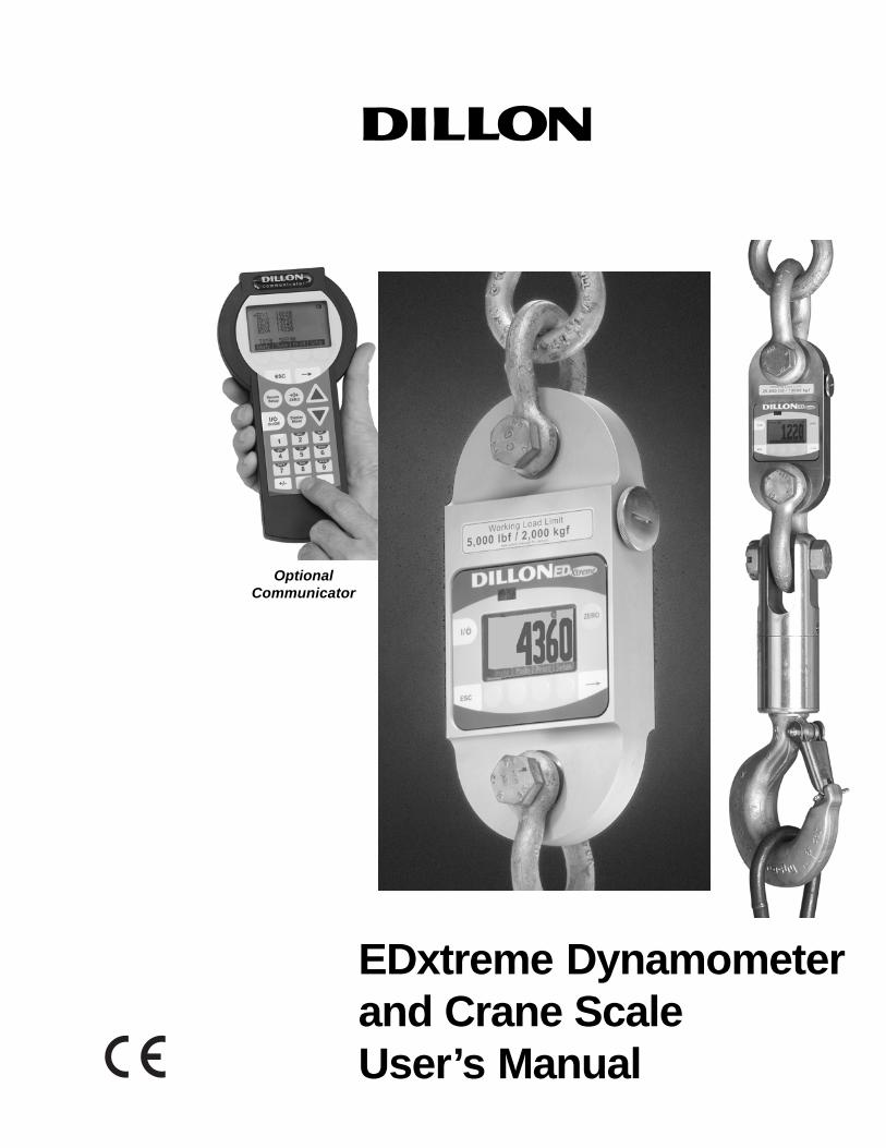
EDxtreme Dynamometerand Crane ScaleUser’s Manual
OptionalCommunicator

2 EDxtreme Dynamometer User’s ManualWeigh Bar® is a registered trademark of Weigh-Tronix Inc.
June 1, 2007 EDX_U.P65 PN 29808-0011 Issue AB Printed in USA
Read and understand this manual before usingthe equipment. Failure to follow instructions
can result in serious injury or death.
3EDxtreme Dynamometer User’s Manual
Table of Contents
Table of Contents ....................................................................................................................... 3Specifications .............................................................................................................................. 4Safe Operation ............................................................................................................................ 5
Radio Safety ......................................................................................................................... 6Radio Communications Reliability ....................................................................................... 6
Introduction ................................................................................................................................. 7EDX & Communicator Description ............................................................................................. 7
EDX Front Panel ................................................................................................................... 7EDxtreme Connector ............................................................................................................ 8Communicator Front Panel .................................................................................................. 8Communicator Connectors .................................................................................................. 9
Power On and Annunciators ..................................................................................................... 10EDX Setup ............................................................................................................................... 11
Setup Menu ........................................................................................................................ 11Configuration ............................................................................................................................ 16
Configuration Menu ............................................................................................................ 17EDX Operation .......................................................................................................................... 24
Display Modes .................................................................................................................... 24Force Measurement ........................................................................................................... 24Force Measurement Rezero ............................................................................................... 24Displaying Peak Force ....................................................................................................... 24
Communicator Operation ......................................................................................................... 26Powerup Display................................................................................................................. 26Setup Menu ........................................................................................................................ 27Config Menu ....................................................................................................................... 28Communicator Print Formats ............................................................................................. 29
General Information .................................................................................................................. 31Changing Batteries ............................................................................................................. 31Battery Life ......................................................................................................................... 31Care ............................................................................................................................... 31Radio Information ............................................................................................................... 31Installing Spacers ............................................................................................................... 32
Common Configurations and Settings ...................................................................................... 34FCC Information........................................................................................................................ 35
Modifications ....................................................................................................................... 35Troubleshooting ........................................................................................................................ 36Weigh and Force Measurement Practice ................................................................................. 38
Load Centering ................................................................................................................... 38Alignment ............................................................................................................................ 38Proper Pin Fit ...................................................................................................................... 38Torque and Bending ........................................................................................................... 38Certified Gear ..................................................................................................................... 38Good Force Measurement Practice ................................................................................... 39
4 EDxtreme Dynamometer User’s Manual
Dynamometer SpecificationsEnclosure: Designed to NEMA4X/IP55. Suitable for continu-
ous outdoor use.
Accuracy: 0.1% of capacity.*
Repeatability: 0.1% of capacity.**1 part in 1000 display mode with Dillon providedshackles.
Factor of safety: 2.5K to 10K = 7:1 USF25K to 100K = 5:1 USF, 220K to 330K 4:1 USF
Body Protection: Aluminum capacities are anodized. Alloysteel capacities are electroless-nickel plated.
Bearings: Unmatched repeatability attained by needlebearings in shackle pin holes up to EDx-10K. Shackle pinacts as inner race.
Shackles: Forged industry standard anchor shackles. Modelsup to EDx-10K use precision machined shackle pin.Higher capacities use forged pin.
Display: 128 x 64 dot-graphic LCD display shows up to 6digits 1.0” (26mm) high plus annunciators and softkeys.Digits are .11 inches (3mm) thick for unmatched read-ability.
Display update rate: 2 times per second.
Connector: Recessed sealed connector may be used forserial communications or connection to a Communicatorremote.
RS-232 / RS-485 communication: Print or extract dataeasily. Continuous output can drive a scoreboard.Configurable poll character.
Calibration: Traceable to the National Institute of Standardsand Technology. Certificate included with curve ofreadings. Passes only with three consecutive confirmingruns, with all points in specification.
Battery life: 320 hours typical use with two C-cell alkalinebatteries. 40 hours typical with Radio Link system.
Operating temperature: -4° F to 140° F (-20° to 60° C)
Included with instrument: Carry case, batteries, manualand certificate of calibration. EDx-50K and EDx-100Kwith shackles include shackle crate and spacers.
Options: Shackles. 2.4 GHz radio board. Display backlight.
Approval: FCC ID: KQL-PKLR2400CAN ID: CAN2268391158ACE #: 89/336/EEC, 98/37/EEC, EN61000-4
Registration: 595129TELEC certification:
Communicator SpecificationsEnclosure: Designed to NEMA 3 / IP44 with optional sleeve.
Suitable for protected outdoor use.
Instrument size: 9.0 x 4.6 x 1.8 inch (228 x 117 x 45mm).
Accuracy: Not applicable. Only sends and receives digitalinformation.
Display: 128 x 64 dot-graphic LCD display can show fullreadings up to 5 instruments.
Battery life: 60 hours wireline, 20 hours radio using four
AA alkaline batteries under typical use.
Operating temperature: -4° F to 140° F (-20° to 60° C)
Connectors: Sealed connectors may be used for serialcommunications and wired connection to an EDxtremedynamometer.
RS-232 communication: Print or extract data easily. Con-tinuous output can drive a scoreboard. Configurable pollcharacter.
Included with remote: Carry case and batteries.
Accessories: Rubberized case protector sleeve.Remote wall mount bracket. Serial and remote cableassemblies.
Radio SpecificationsFCC Certified: For unlicensed low power devices. No radio
licensing or permits required for normal operation.* (Inthe US and Canada. Check local ordinances in othercountries.)
Frequency: 2.4 GHz spread-spectrum operates between2.402 – 2.478 GHz. Continuously and automaticallychanges frequencies many times per second for consis-tent, reliable communications.
Output Level: 10 mW (20 dBm)
Display Update Rate: 2 times per second with singledynamometer. Multi-instrument networks result inreduced updates.
Number of networks: 63 remotes can operate independentlyin the same airspace with unique channels.
Number of links remote can control: Up to 15 addressesare available per network channel.
Configuration: Address and Network channels are front-panel configurable.
Antenna: Integral antenna.
Range: Open-air – Up to 300 feet, line-of-sight.Indoors – Dependent upon installation site with 150 feetcommon.
Specifications
AC3124-10-01
R 003NY0659 0000
5EDxtreme Dynamometer User’s Manual
Keep all the following in mind as you use the EDX dynamometer.
The system capacity is equal to the rating of the dynamometers. Theshackle rating should not be used to determine lift capacity of the system.
The shackles are rated in metric tons. Thus the 12-ton shackles are ratedto 26,450 lbf and are suitable for use on the 25,000 lbf dynamometer.
Any zeroed deadload must be considered as part of the ultimate load.
Although this instrument has a substantial overload protection rating, theinstrument should not be used above the rated capacity. Doing so cansignificantly impact fatigue life of the instrument and cause premature andabrupt failure. If a higher capacity reading is needed, Dillon insists that alarger instrument be used.
Safety is always a concern in overhead lifting and tensioning applications.To limit your liability always insist upon factory supplied shackles and pinsand factory tested and certified safe optional equipment. All DILLONproducts are designed to meet the published Safe Working Load (SWL)and Ultimate Safety Factor (USF) standards of the United States Military.
Do not grind, stamp, drill or deform the metal on the dynamometer body inany way. Protect the instrument from impact in use and storage.
Any significant damage or deformation to the loading element is cause forevaluation by Dillon, particularly in the element side members to the rightand left of the display.
Relieve all torsional and off axis loads.
Apply load in the center of the shackle bow with this instrument.
Off center loading results in substandard performance.
Instrument requires time to stabilize when changing temperatures.
Use only the hardware supplied with this instrument. If no hardware wassupplied, insure that the mating pin and shackle bow is equivalent to thehardware used at calibration. Otherwise substandard performance orfailure can result.
Dillon recommends only using qualified rigging hardware and cannotbe responsible for unapproved hardware.
This instrument is not designed for the following:
• Applications that see rapid, dramatic temperature swings or thermalshock. Wide variation in readings can occur.
• Environments with high electromagnetic fields such as cranes em-ploying electromagnets to lift metal. These induce trace voltages thatare picked up within the load cell lead wiring and appear as inaccu-rate loads.
• Intrinsically safe environments. This unit has not been Factory Mutualtested.
Safe Operation
If you overload this dynamom-eter you could suffer severeinjuries or death. The totalload on the dynamometershould NEVER exceed therated capacity.
CAUTION: Remove batteriesfrom instrument when usingthe external AC power supply.
6 EDxtreme Dynamometer User’s Manual
Radio Safety The radiated output power of this device is far below the FCC radiofrequency exposure limits. Nevertheless, the device shall be used in suchmanner that the potential for human contact during normal operation isminimized.
When connecting an external antenna to the device, the antenna shall beplaced in such a manner to minimize the potential for human contactduring normal operation. In order to avoid the possibility of exceeding theFCC radio frequency exposure limits, human proximity to the antenna shallnot be less than 3 inch (7.5 cm) during normal operation. The antenna islocated at the connector panel on the Communicator.
Radio systems are vulnerable to interference, resulting in delays betweenthe dynamometer scale and remote. In some instances of interference, thedisplay shown on the remote may be several seconds old. This can resultin a hazardous situation when the system is used as the reference foracceptable loads in cases such as proof loading and monitoring of bindingor overload. In these applications where timely updates are critical, acommunication cable should be used to physically connect the EDxtremeand Communicator remote (see setup of RS-485 communications).Alternately, the EDxtreme display can be observed directly.
Radio CommunicationsReliability
Low power radio systemsshould not be used in applica-tions where timely updates ofreadings are required forsafety purposes.
7EDxtreme Dynamometer User’s Manual
IntroductionThe EDxtremeTM (EDX) electronic dynamometer from Dillon is a forcemeasurement load sensor and digital readout in one instrument. The EDXcan be used to measure tension or weight. It can operate stand-alone orbe coupled with a remote Dillon Communicator, via radio communicationor direct wire connection, for improved convenience, functionality andsafety.
This manual covers the setup and operation of the EDX and optionalCommunicator. General information is covered in the right column of eachpage with major sections separated by the black bar shown above. Sub-heads appear in the left column along with any special notes, cautions orwarnings.
This manual covers the following:
• EDX & Communicator Description• EDX Setup• Communicator Setup• EDX & Communicator Operation• Troubleshooting
Be sure to read the safety precautions found in the Safe Operation section.
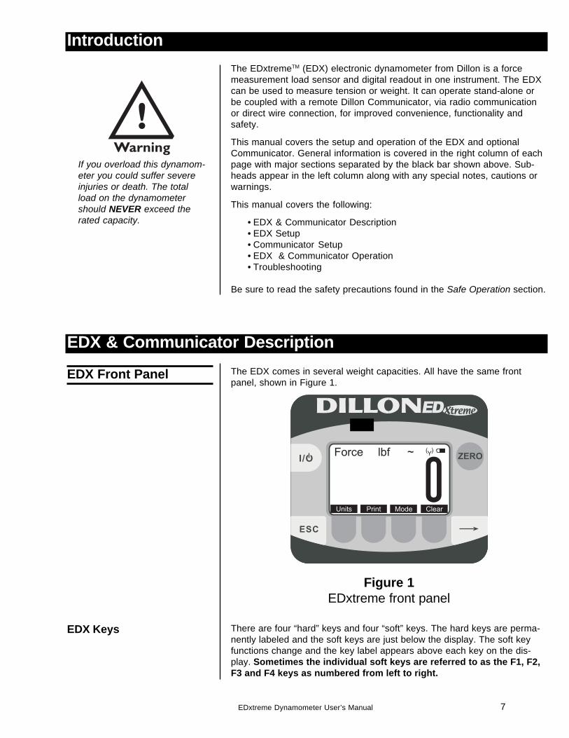
The EDX comes in several weight capacities. All have the same frontpanel, shown in Figure 1.
Figure 1EDxtreme front panel
There are four “hard” keys and four “soft” keys. The hard keys are perma-nently labeled and the soft keys are just below the display. The soft keyfunctions change and the key label appears above each key on the dis-play. Sometimes the individual soft keys are referred to as the F1, F2,F3 and F4 keys as numbered from left to right.
EDX & Communicator Description
EDX Front Panel
EDX Keys
If you overload this dynamom-eter you could suffer severeinjuries or death. The totalload on the dynamometershould NEVER exceed therated capacity.
8 EDxtreme Dynamometer User’s Manual
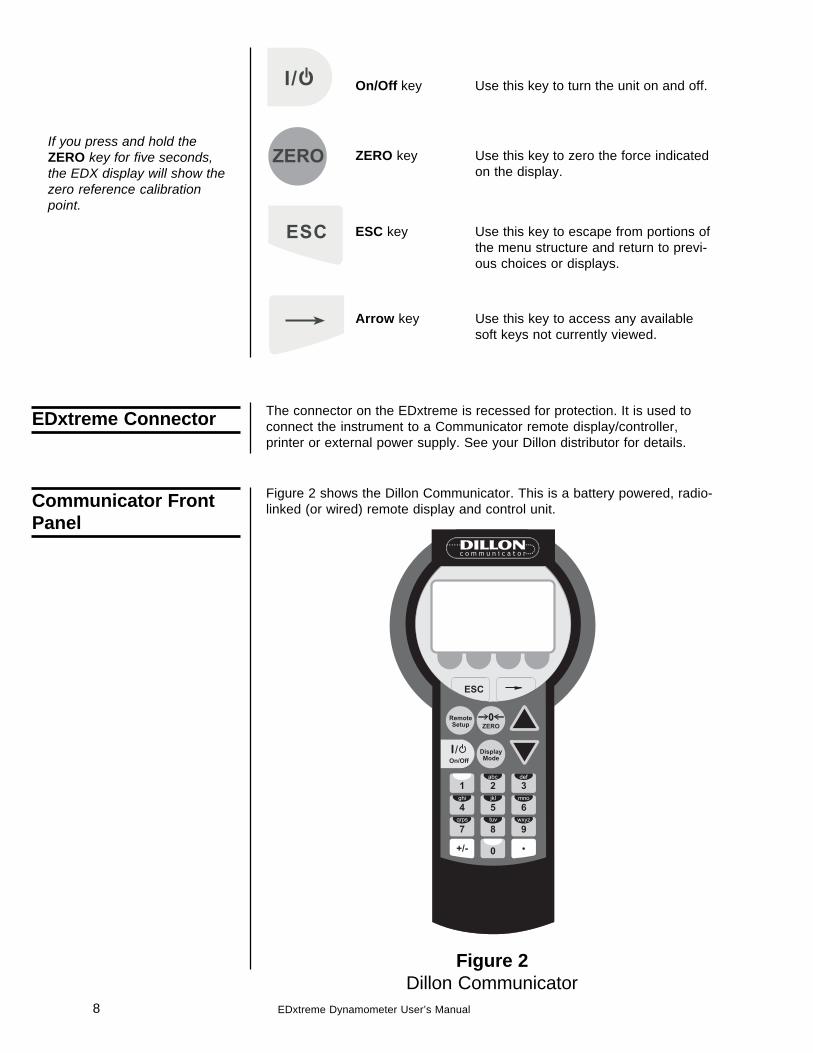
On/Off key Use this key to turn the unit on and off.
ZERO key Use this key to zero the force indicatedon the display.
ESC key Use this key to escape from portions ofthe menu structure and return to previ-ous choices or displays.
Arrow key Use this key to access any availablesoft keys not currently viewed.
Communicator FrontPanel
The connector on the EDxtreme is recessed for protection. It is used toconnect the instrument to a Communicator remote display/controller,printer or external power supply. See your Dillon distributor for details.
Figure 2 shows the Dillon Communicator. This is a battery powered, radio-linked (or wired) remote display and control unit.
Figure 2Dillon Communicator
EDxtreme Connector
If you press and hold theZERO key for five seconds,the EDX display will show thezero reference calibrationpoint.
9EDxtreme Dynamometer User’s Manual
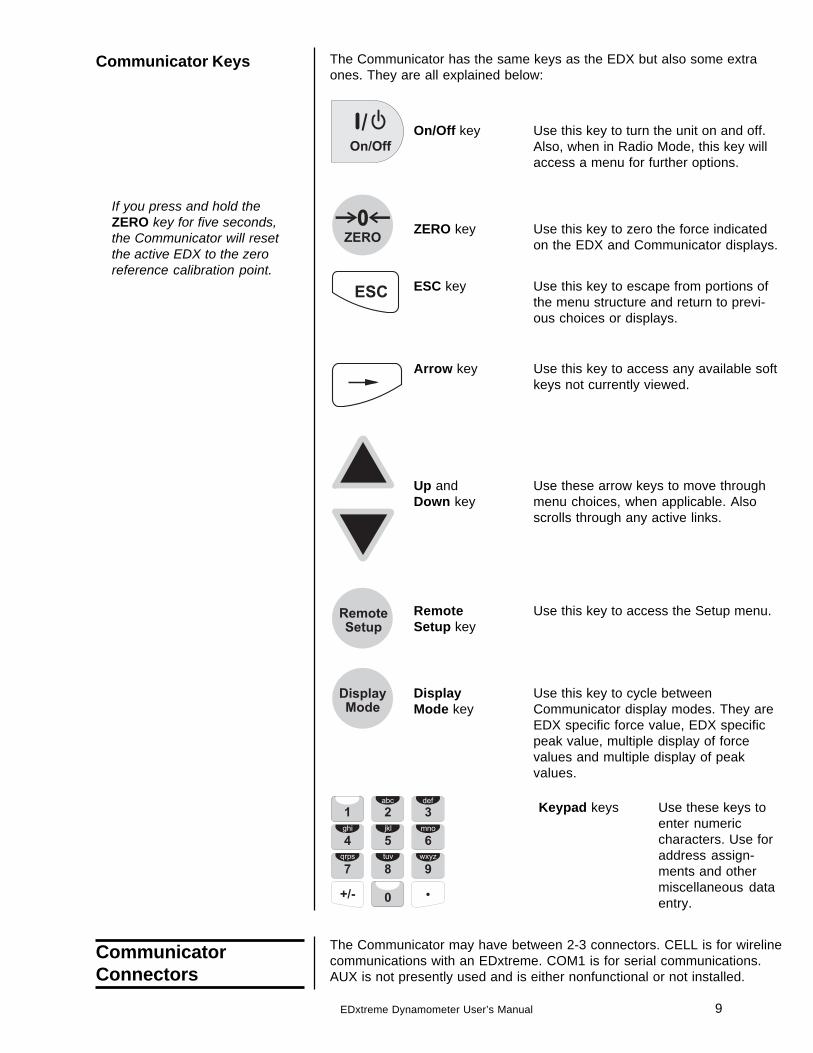
The Communicator has the same keys as the EDX but also some extraones. They are all explained below:
On/Off key Use this key to turn the unit on and off.Also, when in Radio Mode, this key willaccess a menu for further options.
ZERO key Use this key to zero the force indicatedon the EDX and Communicator displays.
ESC key Use this key to escape from portions ofthe menu structure and return to previ-ous choices or displays.
Arrow key Use this key to access any available softkeys not currently viewed.
Up and Use these arrow keys to move throughDown key menu choices, when applicable. Also
scrolls through any active links.
Remote Use this key to access the Setup menu.Setup key
Display Use this key to cycle betweenMode key Communicator display modes. They are
EDX specific force value, EDX specificpeak value, multiple display of forcevalues and multiple display of peakvalues.
Keypad keys Use these keys toenter numericcharacters. Use foraddress assign-ments and othermiscellaneous dataentry.
Communicator Keys
The Communicator may have between 2-3 connectors. CELL is for wirelinecommunications with an EDxtreme. COM1 is for serial communications.AUX is not presently used and is either nonfunctional or not installed.
CommunicatorConnectors
If you press and hold theZERO key for five seconds,the Communicator will resetthe active EDX to the zeroreference calibration point.
10 EDxtreme Dynamometer User’s Manual
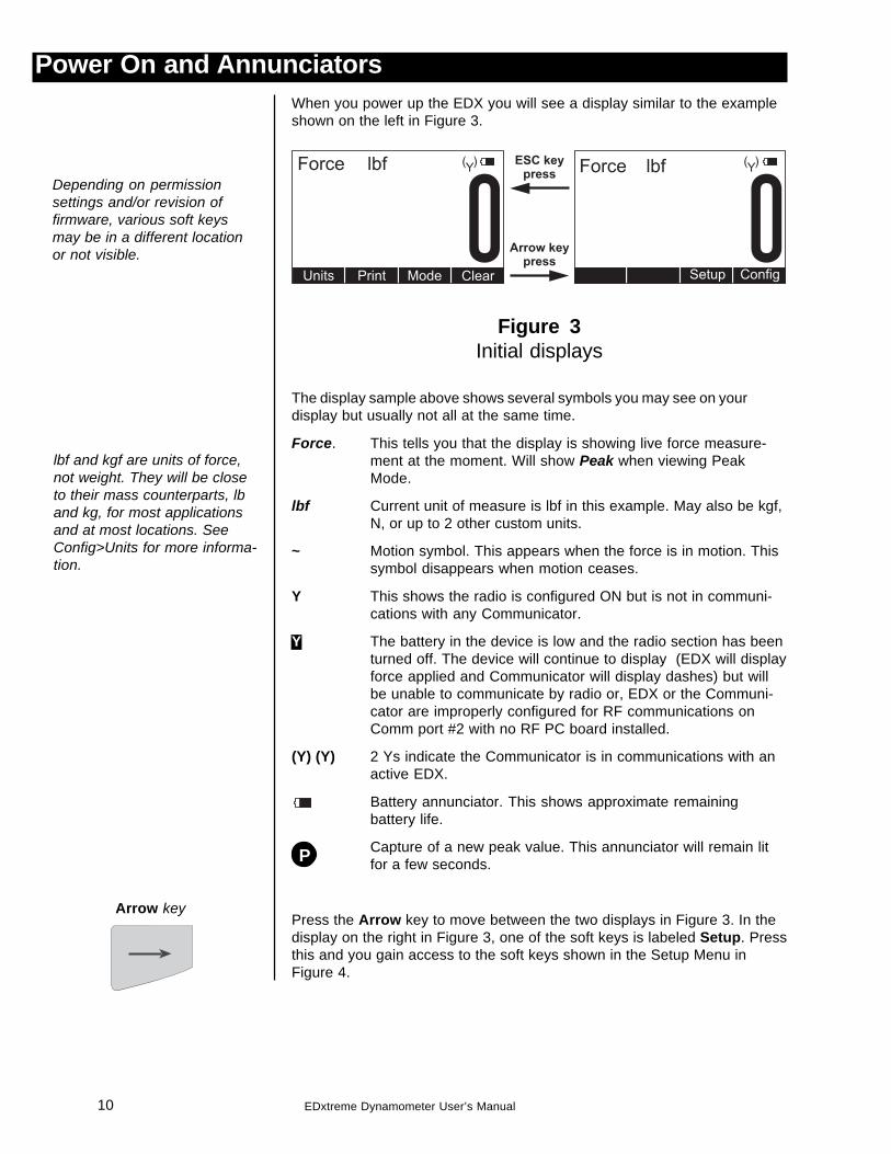
Power On and AnnunciatorsWhen you power up the EDX you will see a display similar to the exampleshown on the left in Figure 3.
Figure 3Initial displays
The display sample above shows several symbols you may see on yourdisplay but usually not all at the same time.
Force. This tells you that the display is showing live force measure-ment at the moment. Will show Peak when viewing PeakMode.
lbf Current unit of measure is lbf in this example. May also be kgf,N, or up to 2 other custom units.
~ Motion symbol. This appears when the force is in motion. Thissymbol disappears when motion ceases.
Y This shows the radio is configured ON but is not in communi-cations with any Communicator.
Y The battery in the device is low and the radio section has beenturned off. The device will continue to display (EDX will displayforce applied and Communicator will display dashes) but willbe unable to communicate by radio or, EDX or the Communi-cator are improperly configured for RF communications onComm port #2 with no RF PC board installed.
(Y) (Y) 2 Ys indicate the Communicator is in communications with anactive EDX.
Battery annunciator. This shows approximate remainingbattery life.
Capture of a new peak value. This annunciator will remain litfor a few seconds.
Press the Arrow key to move between the two displays in Figure 3. In thedisplay on the right in Figure 3, one of the soft keys is labeled Setup. Pressthis and you gain access to the soft keys shown in the Setup Menu inFigure 4.
Arrow key
Depending on permissionsettings and/or revision offirmware, various soft keysmay be in a different locationor not visible.
lbf and kgf are units of force,not weight. They will be closeto their mass counterparts, lband kg, for most applicationsand at most locations. SeeConfig>Units for more informa-tion.
P
11EDxtreme Dynamometer User’s Manual
COM2 COM1
Set comm.parameters(Disabled orRS232 only)
Config
Setup Comm Mode Units ChPwd ResetPower
Referencesetup menu
Set uppower-updisplaymode
Set upauto-shutdown,and shutdown
timer
Set uppower-up
unit ofmeasure, definecustom units andenable/disable
units of measure
ChangeConfigmenu
password
Reset thesystemdefaults
Press
keyArrow
RF
Channel (1-64)
Network ID
RS 485 RS 232
Radio
NetworkIdentifier
En
ter
Enter
Same ascommunicator
Name ofEDX
Same ascommunicator
Reso
SetResolution
Details
Set commsparameters
Figure 4Operator setup menu for the EDxtreme
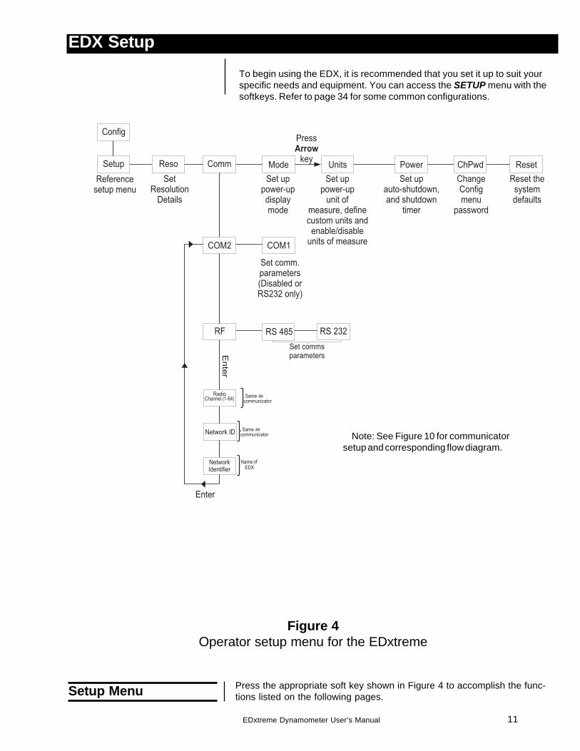
Press the appropriate soft key shown in Figure 4 to accomplish the func-tions listed on the following pages.Setup Menu
EDX SetupTo begin using the EDX, it is recommended that you set it up to suit yourspecific needs and equipment. You can access the SETUP menu with thesoftkeys. Refer to page 34 for some common configurations.
Note: See Figure 10 for communicatorsetup and corresponding flow diagram.
12 EDxtreme Dynamometer User’s Manual
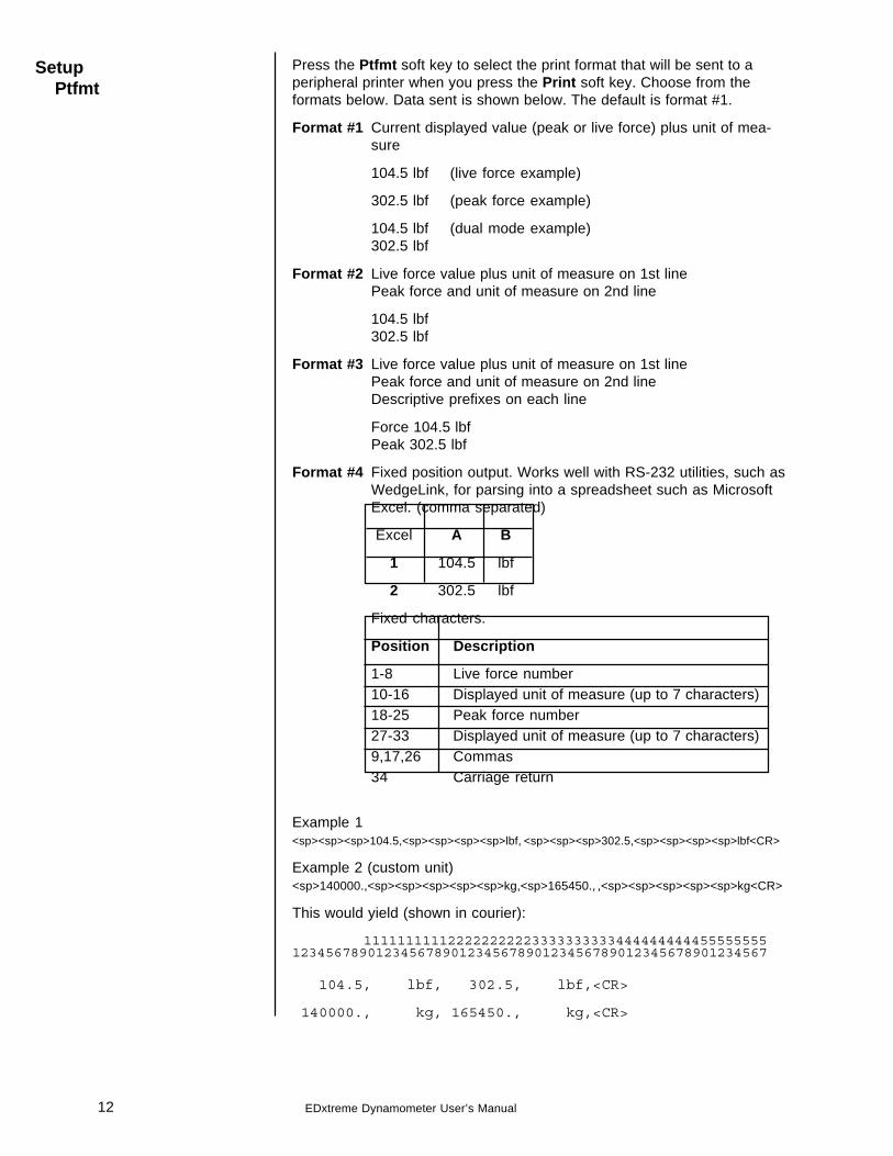
Press the Ptfmt soft key to select the print format that will be sent to aperipheral printer when you press the Print soft key. Choose from theformats below. Data sent is shown below. The default is format #1.
Format #1 Current displayed value (peak or live force) plus unit of mea-sure
104.5 lbf (live force example)
302.5 lbf (peak force example)
104.5 lbf (dual mode example)302.5 lbf
Format #2 Live force value plus unit of measure on 1st linePeak force and unit of measure on 2nd line
104.5 lbf302.5 lbf
Format #3 Live force value plus unit of measure on 1st linePeak force and unit of measure on 2nd lineDescriptive prefixes on each line
Force 104.5 lbfPeak 302.5 lbf
Format #4 Fixed position output. Works well with RS-232 utilities, such asWedgeLink, for parsing into a spreadsheet such as MicrosoftExcel. (comma separated)
Excel A B
1 104.5 lbf
2 302.5 lbf
Fixed characters.
Position Description
1-8 Live force number10-16 Displayed unit of measure (up to 7 characters)18-25 Peak force number27-33 Displayed unit of measure (up to 7 characters)9,17,26 Commas34 Carriage return
Example 1<sp><sp><sp>104.5,<sp><sp><sp><sp>lbf, <sp><sp><sp>302.5,<sp><sp><sp><sp>lbf<CR>
Example 2 (custom unit)<sp>140000.,<sp><sp><sp><sp><sp>kg,<sp>165450., ,<sp><sp><sp><sp><sp>kg<CR>
This would yield (shown in courier):
111111111122222222223333333333444444444455555555123456789012345678901234567890123456789012345678901234567
104.5, lbf, 302.5, lbf,<CR>
140000., kg, 165450., kg,<CR>
SetupPtfmt

13EDxtreme Dynamometer User’s Manual
Format #5 Live force, unit of measure, peak force, unit of measure. All tabseparated.
104.5<tab>lbf<CR> (if presently displaying live readings)
302.5<tab>lbf<CR> (if presently displaying peak readings)
104.5<tab>lbf<tab>302.5<tab>lbf<CR> (if presently displayingdual mode)
14 EDxtreme Dynamometer User’s Manual
SetupMisc
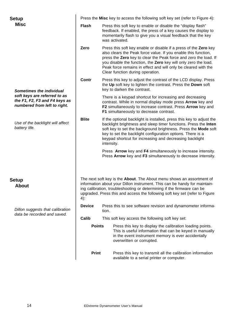
Press the Misc key to access the following soft key set (refer to Figure 4):
Flash Press this soft key to enable or disable the “display flash”feedback. If enabled, the press of a key causes the display tomomentarily flash to give you a visual feedback that the keywas activated.
Zero Press this soft key enable or disable if a press of the Zero keyalso clears the Peak force value. If you enable this function,press the Zero key to clear the Peak force and zero the load. Ifyou disable the function, the Zero key will only zero the load.Peak force remains in effect and will only be cleared with theClear function during operation.
Contr Press this key to adjust the contrast of the LCD display. Pressthe Up soft key to lighten the contrast. Press the Down softkey to darken the contrast.
There is a keypad shortcut for increasing and decreasingcontrast. While in normal display mode press Arrow key andF2 simultaneously to increase contrast. Press Arrow key andF1 simultaneously to decrease contrast.
Blite If the optional backlight is installed, press this key to adjust thebacklight brightness and sleep timer functions. Press the Intensoft key to set the background brightness. Press the Mode softkey to set the backlight configuration options. There is akeypad shortcut for increasing and decreasing backlightintensity.
Press Arrow key and F4 simultaneously to increase intensity.Press Arrow key and F3 simultaneously to decrease intensity.
The next soft key is the About. The About menu shows an assortment ofinformation about your Dillon instrument. This can be handy for maintain-ing calibration, troubleshooting or determining if the firmware can beupgraded. Press this and access the following soft key set (refer to Figure4):
Device Press this to see software revision and dynamometer informa-tion.
Calib This soft key access the following soft key set:
Points Press this key to display the calibration loading points.This is useful information that can be keyed in manuallyin the event instrument memory is ever accidentallyoverwritten or corrupted.
Print Press this key to transmit all the calibration informationavailable to a serial printer or computer.
SetupAbout
Dillon suggests that calibrationdata be recorded and saved.
Use of the backlight will affectbattery life.
Sometimes the individualsoft keys are referred to asthe F1, F2, F3 and F4 keys asnumbered from left to right.
15EDxtreme Dynamometer User’s Manual
SetupTest
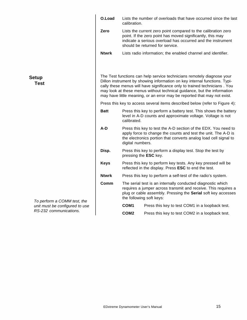
O.Load Lists the number of overloads that have occurred since the lastcalibration.
Zero Lists the current zero point compared to the calibration zeropoint. If the zero point has moved significantly, this mayindicate a serious overload has occurred and the instrumentshould be returned for service.
Ntwrk Lists radio information; the enabled channel and identifier.
The Test functions can help service technicians remotely diagnose yourDillon instrument by showing information on key internal functions. Typi-cally these menus will have significance only to trained technicians . Youmay look at these menus without technical guidance, but the informationmay have little meaning, or an error may be reported that may not exist.
Press this key to access several items described below (refer to Figure 4):
Batt Press this key to perform a battery test. This shows the batterylevel in A-D counts and approximate voltage. Voltage is notcalibrated.
A-D Press this key to test the A-D section of the EDX. You need toapply force to change the counts and test the unit. The A-D isthe electronics portion that converts analog load cell signal todigital numbers.
Disp. Press this key to perform a display test. Stop the test bypressing the ESC key.
Keys Press this key to perform key tests. Any key pressed will bereflected in the display. Press ESC to end the test.
Ntwrk Press this key to perform a self-test of the radio’s system.
Comm The serial test is an internally conducted diagnostic whichrequires a jumper across transmit and receive. This requires aplug or cable assembly. Pressing the Serial soft key accessesthe following soft keys:
COM1 Press this key to test COM1 in a loopback test.
COM2 Press this key to test COM2 in a loopback test.
To perform a COMM test, theunit must be configured to useRS-232 communications.
16 EDxtreme Dynamometer User’s Manual
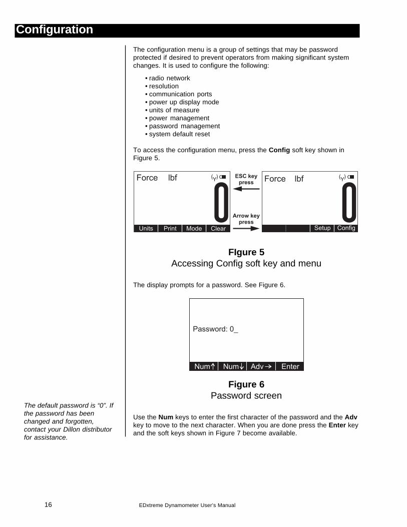
ConfigurationThe configuration menu is a group of settings that may be passwordprotected if desired to prevent operators from making significant systemchanges. It is used to configure the following:
• radio network• resolution• communication ports• power up display mode• units of measure• power management• password management• system default reset
To access the configuration menu, press the Config soft key shown inFigure 5.
FIgure 5Accessing Config soft key and menu
The display prompts for a password. See Figure 6.
Figure 6Password screen
Use the Num keys to enter the first character of the password and the Advkey to move to the next character. When you are done press the Enter keyand the soft keys shown in Figure 7 become available.
The default password is “0”. Ifthe password has beenchanged and forgotten,contact your Dillon distributorfor assistance.
17EDxtreme Dynamometer User’s Manual
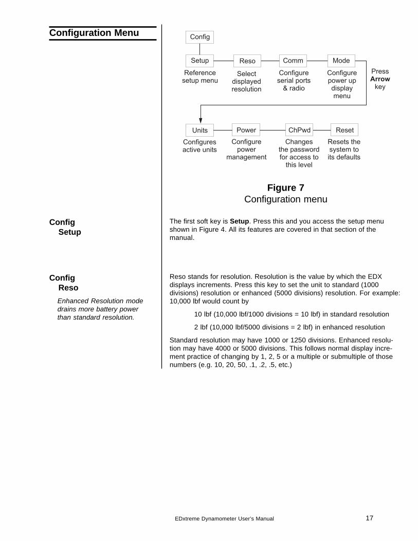
Figure 7Configuration menu
The first soft key is Setup. Press this and you access the setup menushown in Figure 4. All its features are covered in that section of themanual.
Reso stands for resolution. Resolution is the value by which the EDXdisplays increments. Press this key to set the unit to standard (1000divisions) resolution or enhanced (5000 divisions) resolution. For example:10,000 lbf would count by
10 lbf (10,000 lbf/1000 divisions = 10 lbf) in standard resolution
2 lbf (10,000 lbf/5000 divisions = 2 lbf) in enhanced resolution
Standard resolution may have 1000 or 1250 divisions. Enhanced resolu-tion may have 4000 or 5000 divisions. This follows normal display incre-ment practice of changing by 1, 2, 5 or a multiple or submultiple of thosenumbers (e.g. 10, 20, 50, .1, .2, .5, etc.)
ConfigSetup
ConfigReso
Configuration Menu
Enhanced Resolution modedrains more battery powerthan standard resolution.
18 EDxtreme Dynamometer User’s Manual
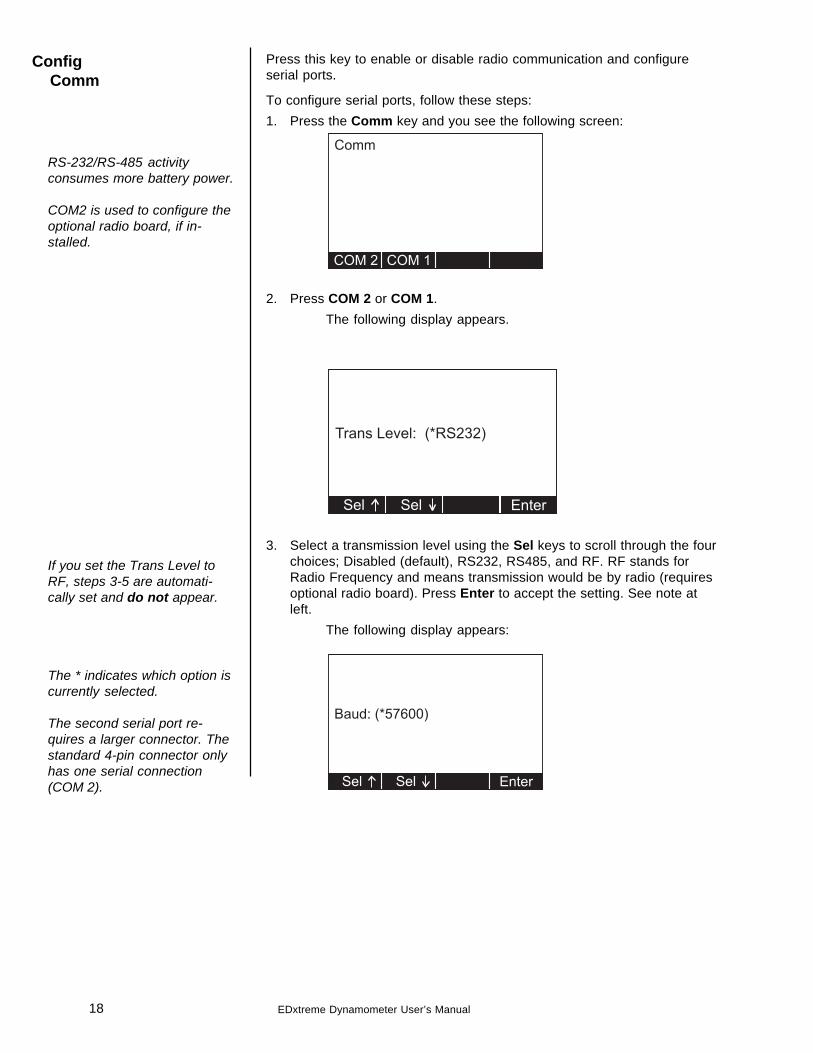
Press this key to enable or disable radio communication and configureserial ports.
To configure serial ports, follow these steps:1. Press the Comm key and you see the following screen:
2. Press COM 2 or COM 1.The following display appears.
3. Select a transmission level using the Sel keys to scroll through the fourchoices; Disabled (default), RS232, RS485, and RF. RF stands forRadio Frequency and means transmission would be by radio (requiresoptional radio board). Press Enter to accept the setting. See note atleft.
The following display appears:
RS-232/RS-485 activityconsumes more battery power.
COM2 is used to configure theoptional radio board, if in-stalled.
ConfigComm
The * indicates which option iscurrently selected.
The second serial port re-quires a larger connector. Thestandard 4-pin connector onlyhas one serial connection(COM 2).
If you set the Trans Level toRF, steps 3-5 are automati-cally set and do not appear.
19EDxtreme Dynamometer User’s Manual
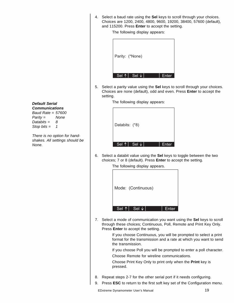
4. Select a baud rate using the Sel keys to scroll through your choices.Choices are 1200, 2400, 4800, 9600, 19200, 38400, 57600 (default),and 115200. Press Enter to accept the setting.
The following display appears:
5. Select a parity value using the Sel keys to scroll through your choices.Choices are none (default), odd and even. Press Enter to accept thesetting.
The following display appears:
6. Select a databit value using the Sel keys to toggle between the twochoices; 7 or 8 (default). Press Enter to accept the setting.
The following display appears.
7. Select a mode of communication you want using the Sel keys to scrollthrough these choices; Continuous, Poll, Remote and Print Key Only.Press Enter to accept the setting.
If you choose Continuous, you will be prompted to select a printformat for the transmission and a rate at which you want to sendthe transmission.If you choose Poll you will be prompted to enter a poll character.Choose Remote for wireline communications.Choose Print Key Only to print only when the Print key ispressed.
8. Repeat steps 2-7 for the other serial port if it needs configuring.9. Press ESC to return to the first soft key set of the Configuration menu.
Default SerialCommunicationsBaud Rate = 57600Parity = NoneDatabits = 8Stop bits = 1
There is no option for hand-shakes. All settings should beNone.
20 EDxtreme Dynamometer User’s Manual
If you enable the radio:
You are asked to enter a Radio Channel. Your EDX and Communicatormust be on the same channel to function together. Key in a number from 1through 64. 1 is the default setting. Press Enter to accept.
You are asked to enter a Network ID#. This is a unique address number (1-15) so the Communicator only speaks to one instrument at a time without“cross-talking.” Use the available soft keys to enter a number (1-15), thenpress Enter to accept.
You are then asked to key in an alternate network identifier. Use theavailable soft keys to enter alpha characters, then press Enter to accept.
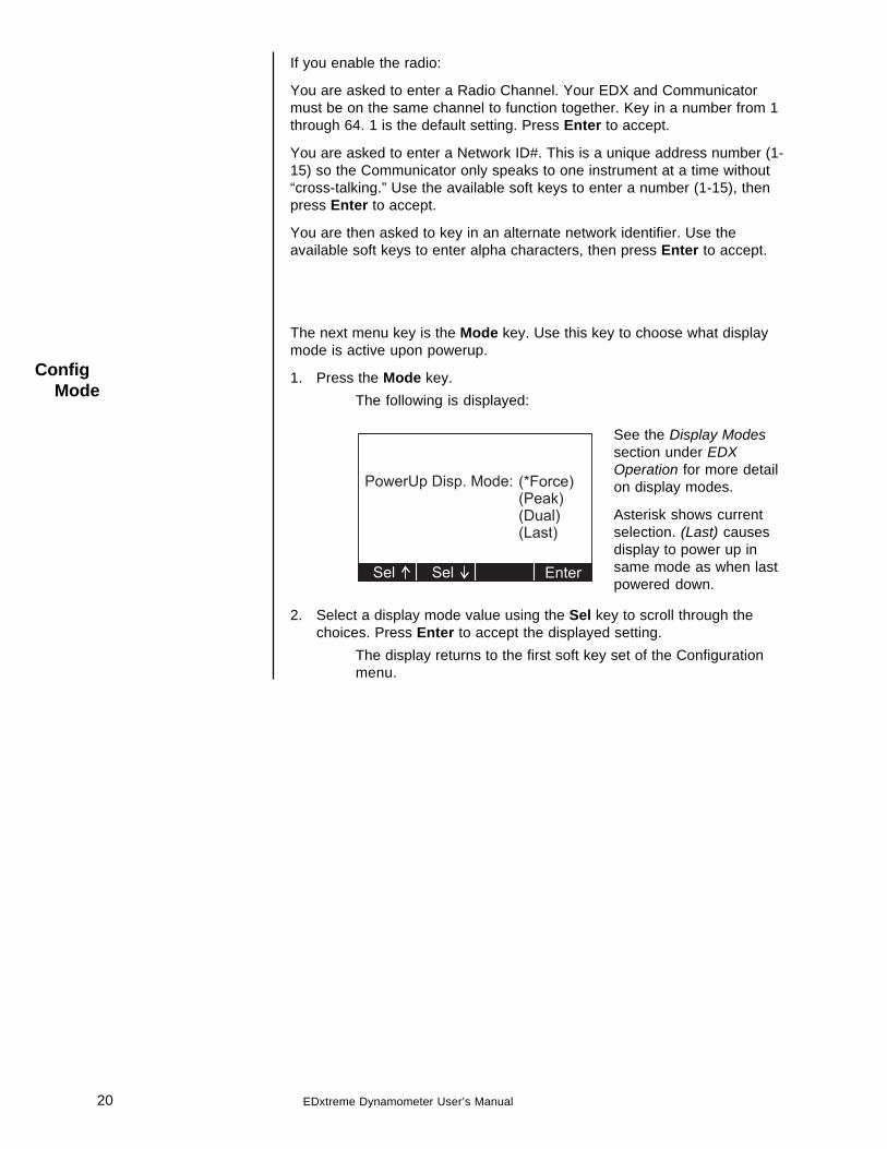
The next menu key is the Mode key. Use this key to choose what displaymode is active upon powerup.
1. Press the Mode key.The following is displayed:
2. Select a display mode value using the Sel key to scroll through thechoices. Press Enter to accept the displayed setting.
The display returns to the first soft key set of the Configurationmenu.
ConfigMode
See the Display Modessection under EDXOperation for more detailon display modes.
Asterisk shows currentselection. (Last) causesdisplay to power up insame mode as when lastpowered down.

21EDxtreme Dynamometer User’s Manual
The next soft key is Units. Use this item to set the units of measure youwant available when you use the Units key in the normal operating mode.This can also assign custom units.
Custom units are typically used for any of three purposes:
1. To display a unit of measure not found in the standard options, such aston, tonne, dyne, or KIP.
2. To apply a multiplier when multipart line systems or other static linearrangements are used. For example, if a 4-part line is used, thedynamometer at the dead end can display approximate total weight byusing a multiplier of 4.
It is critical that the operator understands the relationship between thedynamometer and custom unit. For example, assume a custom unit ofkg is entered where 1 kg = 5 kgf (as seen at the dynamometer). Theoperator could become confused, think that a 1000 kg display meansthat there is still 4000 kg of capacity remaining.
3. To compensate for local gravitational differences. There are variancesin gravity throughout the world. If used as a scale, variances due togravitational differences can be handled by having the instrumentcalibrated on-site with certified dead weights or by using the customunits. Simply divide the gravitational constant at your location by9.80665 m/ss (or 32.1741 ft/s2) and use this as the multiplier entry. Aless accurate alternative : If the constant is not known, lift a weight ofknown mass close to the capacity of the instrument. In enhancedresolution mode, observe the reading. Divide the actual by the ob-served reading and use this as the multiplier entry.
ConfigUnits
22 EDxtreme Dynamometer User’s Manual
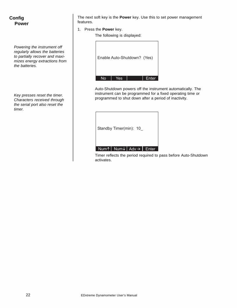
The next soft key is the Power key. Use this to set power managementfeatures.
1. Press the Power key.The following is displayed:
Auto-Shutdown powers off the instrument automatically. Theinstrument can be programmed for a fixed operating time orprogrammed to shut down after a period of inactivity.
Timer reflects the period required to pass before Auto-Shutdownactivates.
ConfigPower
Key presses reset the timer.Characters received throughthe serial port also reset thetimer.
Powering the instrument offregularly allows the batteriesto partially recover and maxi-mizes energy extractions fromthe batteries.
23EDxtreme Dynamometer User’s Manual
ConfigReset
ConfigChPwd
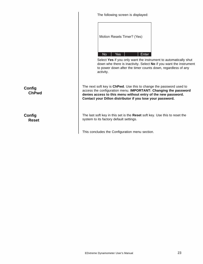
The following screen is displayed:
Select Yes if you only want the instrument to automatically shutdown whe there is inactivity. Select No if you want the instrumentto power down after the timer counts down, regardless of anyactivity.
The next soft key is ChPwd. Use this to change the password used toaccess the configuration menu. IMPORTANT: Changing the passworddenies access to this menu without entry of the new password.Contact your Dillon distributor if you lose your password.
The last soft key in this set is the Reset soft key. Use this to reset thesystem to its factory default settings.
This concludes the Configuration menu section.
24 EDxtreme Dynamometer User’s Manual
EDX Operation
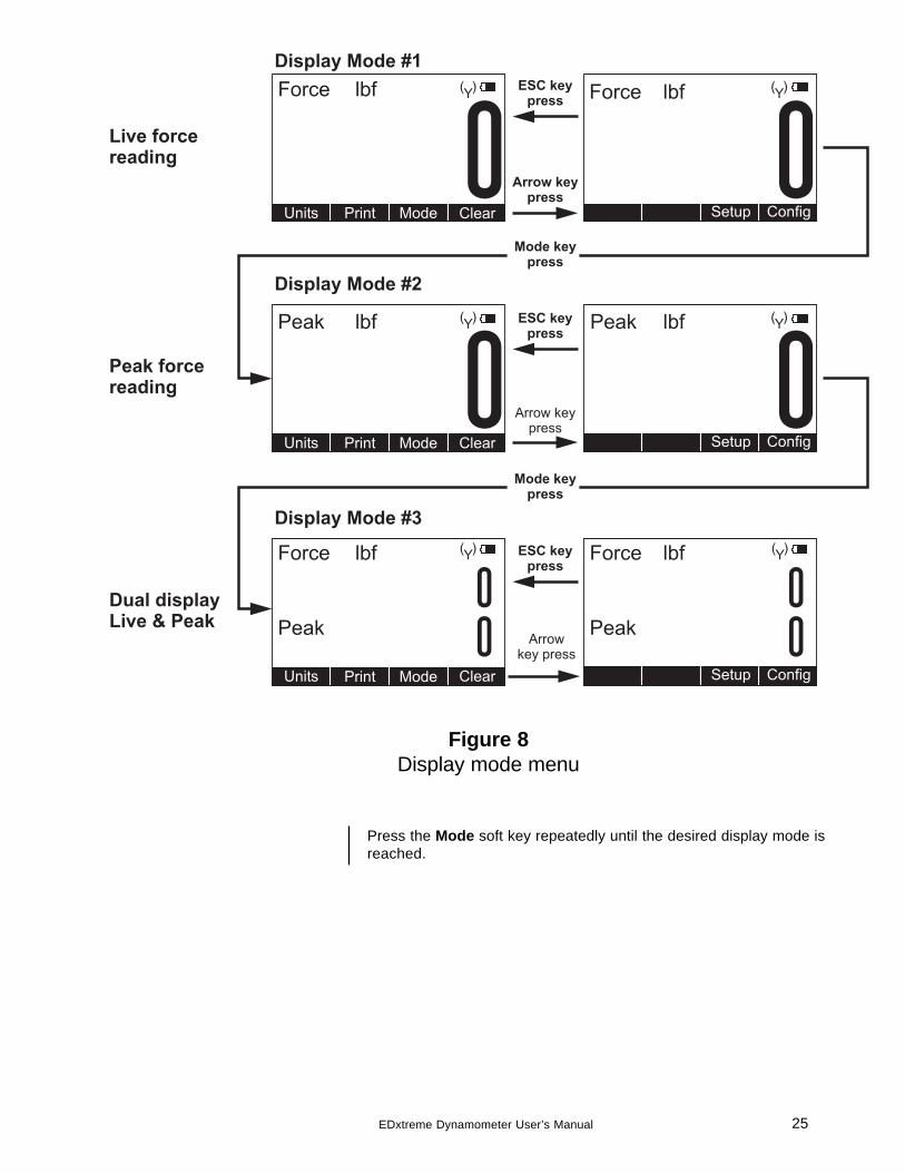
Display Modes The EDX has several display modes accessible by pressing the Mode softkey. See Figure 8.
The first display mode when you power up is the live force measurementmode.
Press the Mode soft key and the display changes to peak measurementmode. This mode shows the peak force applied to the EDX since the lastpeak clearing action. Delete the peak reading by pressing the Clear softkey.
Press the Mode soft key again and the display shows live force and peakreadings simultaneously.
Press the Mode soft key again and the display returns to the force mea-surement mode.
Follow these steps to perform a gross force measurement.
1. Turn on the unit with the On/Off key.
2. Remove any weight from the EDX.
3. Zero the EDX by pressing the ZERO key.
4. Apply the force to the EDX and read the gross force on the display.
You can change the units of measure of the display by pressing the Unitssoft key. See note at left. Zero reference is maintained after instrumentpower off and will be recalled with the next power-on. Zero reference maybe lost if battery power is removed.
Rezeroing allows the weight or load of fixturing to be invisible to themeasurement. The zeroed load must always be considered as part ofthe maximum capacity.
1. Turn on the unit with the On/Off key.
2. Remove any weight from the EDX.
3. Zero the EDX by pressing the ZERO key.
4. Apply the tare force to the EDX and press the ZERO key.
5. Apply the force to the EDX and read the net force on the display.
Steps 2 and 3 are not required if the weight of the fixturing is not needed.This should be maintained, however, to know cumulative loads.
The EDX will store the peak force applied until that reading is cleared. Todisplay the peak force applied to an EDX, from the force measurementmode, press the Mode soft key. The display changes to display menu #2shown in Figure 8 which is the peak display mode. The peak force isdisplayed. You can clear this by pressing the Clear soft key.
Peak reading is maintained after instrument power off and will be recalledwith the next power-on. Peak reading may be lost if battery power isremoved.
Force Measurement
Force MeasurementRezero
Displaying Peak Force
Power up display modes maybe configured. SeeConfig>Mode section.
Unit of measure can bechanged only if multiple unitsare enabled in the Configura-tion menu.
25EDxtreme Dynamometer User’s Manual
Figure 8Display mode menu
Press the Mode soft key repeatedly until the desired display mode isreached.
26 EDxtreme Dynamometer User’s Manual
Communicator Operation
The Dillon Communicator is a remote display and control module designedto work with the EDxtreme. It can be connected by wire or can communi-cate by radio if both the Communicator and EDxtreme are equipped withoptional radio boards.
The Communicator may simultaneously view and control several dyna-mometers at one time. Each is monitored individually by assigning uniquenumeric identifiers to each (addresses).
Several Communicators may operate in the same airspace if they are ondifferent channels.
For best performance always have different identifiers for EDxtremeswithin the same network and use different channels for systems operatinganywhere close to one another.
Since most functions are identical, you should refer to the EDxtremesection for comprehensive explanation and the Communicator’s sectionwill highlight differences that exist.
The Communicator is designed to be similar in layout and function to anEDxtreme to make operation easy and intuitive. The main screen appearsas it does on the EDxtreme except that the Mode soft key has beenblanked. This has an actual hard key on the remote.
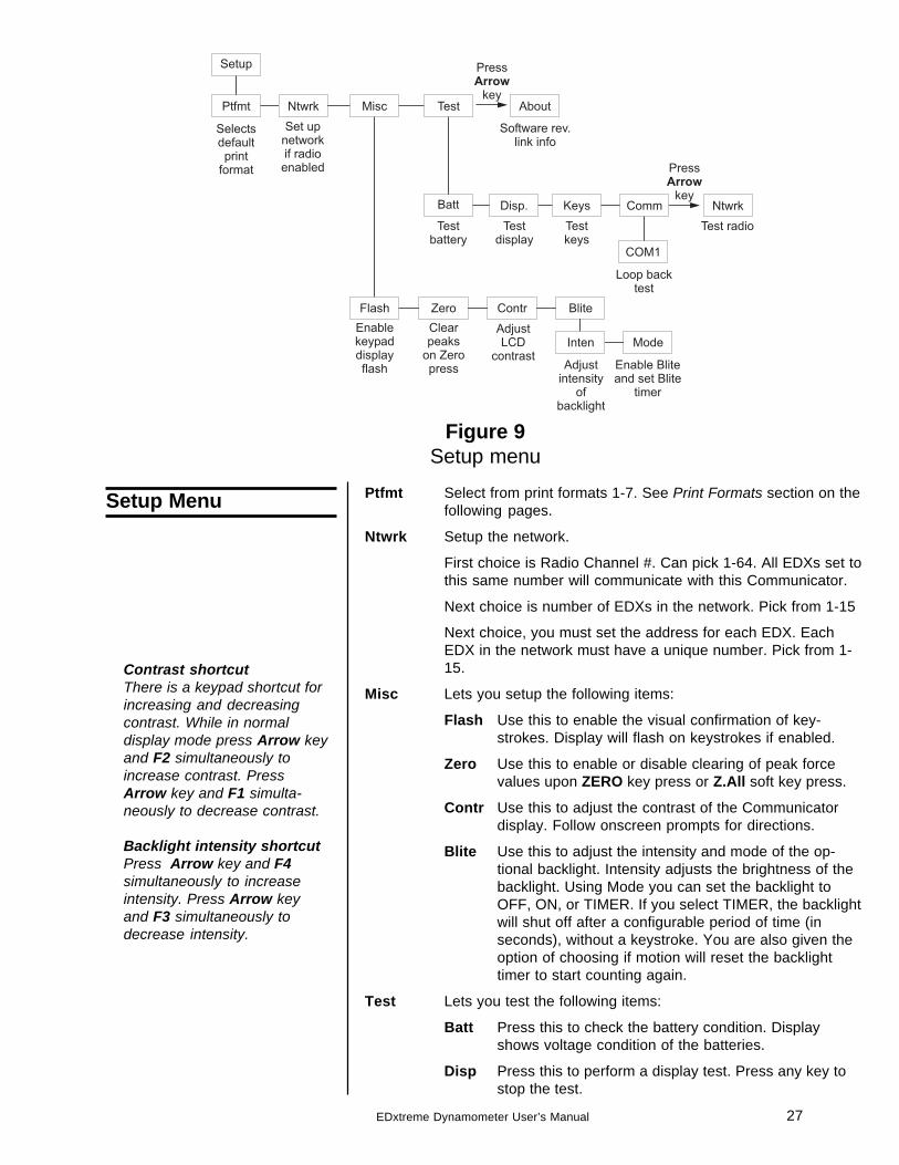
An example of a Communicator’s powerup display is shown below:
There are three soft keys on the first display and 4 on the second display.The soft key functions are described below:
Units Changes the displayed unit of measure. Each press advancesthe display through this sequence; lbf, kgf, N, custom 1,custom 2.
Print Outputs serial data to peripheral devices attached to COM 1.
C.All Clears the peaks on all EDXs currently in communication withthe remote.
Clear Clears the current peak value of the active EDX.
UZ.All Resets all EDXs to calibration zero reference point.
Z.All Zeros all EDXs currently in communication with the remote.
Setup Accesses the Setup menu shown in Figure 9.
Config Accesses the Config menu shown in Figure 10.
Powerup Display
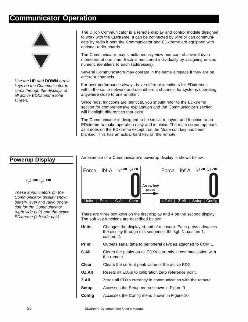
Use the UP and DOWN arrowkeys on the Communicator toscroll through the displays ofall active EDXs and a totalscreen.
These annunciators on theCommunicator display showbattery level and radio opera-tion for the Communicator(right side pair) and the activeEDxtreme (left side pair).
27EDxtreme Dynamometer User’s Manual
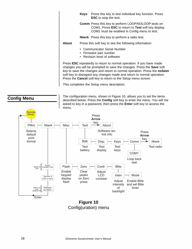
Figure 9Setup menu
Ptfmt Select from print formats 1-7. See Print Formats section on thefollowing pages.
Ntwrk Setup the network.
First choice is Radio Channel #. Can pick 1-64. All EDXs set tothis same number will communicate with this Communicator.
Next choice is number of EDXs in the network. Pick from 1-15
Next choice, you must set the address for each EDX. EachEDX in the network must have a unique number. Pick from 1-15.
Misc Lets you setup the following items:
Flash Use this to enable the visual confirmation of key-strokes. Display will flash on keystrokes if enabled.
Zero Use this to enable or disable clearing of peak forcevalues upon ZERO key press or Z.All soft key press.
Contr Use this to adjust the contrast of the Communicatordisplay. Follow onscreen prompts for directions.
Blite Use this to adjust the intensity and mode of the op-tional backlight. Intensity adjusts the brightness of thebacklight. Using Mode you can set the backlight toOFF, ON, or TIMER. If you select TIMER, the backlightwill shut off after a configurable period of time (inseconds), without a keystroke. You are also given theoption of choosing if motion will reset the backlighttimer to start counting again.
Test Lets you test the following items:
Batt Press this to check the battery condition. Displayshows voltage condition of the batteries.
Disp Press this to perform a display test. Press any key tostop the test.
Setup Menu
Contrast shortcutThere is a keypad shortcut forincreasing and decreasingcontrast. While in normaldisplay mode press Arrow keyand F2 simultaneously toincrease contrast. PressArrow key and F1 simulta-neously to decrease contrast.
Backlight intensity shortcutPress Arrow key and F4simultaneously to increaseintensity. Press Arrow keyand F3 simultaneously todecrease intensity.
28 EDxtreme Dynamometer User’s Manual
Keys Press this key to test individual key function. PressESC to stop the test.
Comm Press this key to perform LOOP/NOLOOP tests onCOM1. Press ESC to return to Test soft key display.COM1 must be enabled in Config menu to test.
Ntwrk Press this key to perform a radio test.
About Press this soft key to see the following information:
• Communicator Serial Number• Firmware part number• Revision level of software
Press ESC repeatedly to return to normal operation. If you have madechanges you will be prompted to save the changes. Press the Save softkey to save the changes and return to normal operation. Press the noSavesoft key to disregard any changes made and return to normal operation.Press the Cancel soft key to return to the Setup menu screen.
This completes the Setup menu description.
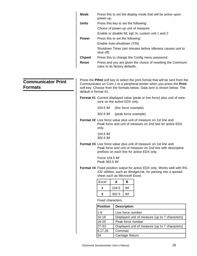
The configuration menu, shown in Figure 10, allows you to set the itemsdescribed below. Press the Config soft key to enter the menu. You will measked to key in a password, then press the Enter soft key to access themenu.
Config Menu
Figure 10Config(uration) menu
Setup
Misc
Flash Zero Contr Blite
Inten Mode
Ptfmt
Selectsdefaultprint
format
About
Software rev.link info
Enablekeypaddisplayflash
Clearpeaks
on Zeropress
AdjustLCD
contrastAdjust
intensityof
backlight
Enable Bliteand set Blite
timer
Test
Disp.
Testdisplay
Keys
Testkeys
Ntwrk
Ntwrk
Test radio
Batt
Testbattery
Press
keyArrow
Press
keyArrow
Comm
COM1
Loop backtest
Channel (1-64)
Number of
Radio
Addressfor EDX 1
Enter
Same asEDX
Same asEDX
EDX in ntwrk
Network ID
Remote
29EDxtreme Dynamometer User’s Manual
Mode Press this to set the display mode that will be active uponpower-up.
Units Press this key to set the following:Choice of power-up unit of measureEnable or disable lbf, kgf, N, custom unit 1 and 2
Power Press this to set the following:Enable Auto-shutdown (Y/N)Shutdown Timer (set minutes before idleness causes unit toshut off)
Chpwd Press this to change the Config menu password.Reset Press and you are given the choice of resetting the Communi-
cator to its factory defaults.
Communicator PrintFormats
Press the Ptfmt soft key to select the print format that will be sent from theCommunicator on Com 1 to a peripheral printer when you press the Printsoft key. Choose from the formats below. Data sent is shown below. Thedefault is format #1.
Format #1 Current displayed value (peak or live force) plus unit of mea-sure on the active EDX only.
104.5 lbf (live force example)
302.5 lbf (peak force example)
Format #2 Live force value plus unit of measure on 1st line andPeak force and unit of measure on 2nd line for active EDXonly.
104.5 lbf302.5 lbf
Format #3 Live force value plus unit of measure on 1st line andPeak force and unit of measure on 2nd line with descriptiveprefixes on each line for active EDX only.
Force 104.5 lbfPeak 302.5 lbf
Format #4 Fixed position output for active EDX only. Works well with RS-232 utilities, such as WedgeLink, for parsing into a spread-sheet such as Microsoft Excel.
Excel A B
1 104.5 lbf
2 302.5 lbf
Fixed characters.
Position Description
1-8 Live force number10-16 Displayed unit of measure (up to 7 characters)18-25 Peak force number27-33 Displayed unit of measure (up to 7 characters)9,17,26 Commas34 Carriage Return
30 EDxtreme Dynamometer User’s Manual
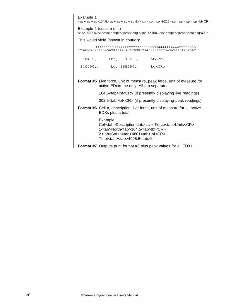
Example 1<sp><sp><sp>104.5,<sp><sp><sp><sp>lbf,<sp><sp><sp>302.5,<sp><sp><sp><sp>lbf<CR>
Example 2 (custom unit)<sp>140000.,<sp><sp><sp><sp><sp>kg,<sp>165450., ,<sp><sp><sp><sp><sp>kg<CR>
This would yield (shown in courier):
111111111122222222223333333333444444444455555555123456789012345678901234567890123456789012345678901234567
104.5, lbf, 302.5, lbf<CR>
140000., kg, 165450., kg<CR>
Format #5 Live force, unit of measure, peak force, unit of measure foractive EDxtreme only. All tab separated.
104.5<tab>lbf<CR> (if presently displaying live readings)
302.5<tab>lbf<CR> (if presently displaying peak readings)
Format #6 Cell #, description, live force, unit of measure for all activeEDXs plus a total.
Example:Cell<tab>Description<tab>Live Force<tab>Units<CR>1<tab>North<tab>104.5<tab>lbf<CR>2<tab>South<tab>4801<tab>lbf<CR>Total<tab><tab>4905.5<tab>lbf
Format #7 Outputs print format #6 plus peak values for all EDXs.
31EDxtreme Dynamometer User’s Manual
General Information
Changing Batteries
Battery Life
Care
Radio Information
To replace discharged batteries, unscrew the battery compartment cap onthe right side of the dynamometer. Remove the two C cells and replacethem with the + poles inserted first. If the spring in the cap becomesdetached, you can reattach it by aligning the large end over thecounterbored hole and turning the spring counterclockwise while pushingthe spring into the hole. The spring will work into the recess and be self-retained.
The Communicator has 4 AA batteries. To replace, remove rear batterycover and replace with fresh batteries in the proper arrangement.
The time required between battery changes can vary with usage, functionsenabled, temperature, duration of use and recovery time, display updaterate, battery grade and more.
To maximize battery life:
• Disable radio if not being used. Even if an optional radio board is notinstalled, the software will run, if enabled.
• Disable other functions such as RS-232 and backlight.• Warm environments result in longer battery life over cool environ-
ments.• Use high quality alkaline batteries.• Turn off instrument when not in use. Alkaline batteries partially
recover when the instrument is off.
The EDxtreme is built to be rugged and endure typical industrial andcommercial use. It is still, however, a precision instrument that should betreated with care. Store the instrument in its carry case with power off.Remove batteries if not being used.
The radio technology used in the radio equipped EDxtreme and Communi-cator is a 2.4 GHz digital spread spectrum system designed for communi-cations reliability. Radio operation and the performance attained can bedifficult to predict and will vary with environment and conditions. There arelocations where radio use is impractical or even impossible.
Tips for best performance:• Keep the Communicator and EDxtreme as close as possible together.• Keep metal and other dense objects as far from the instruments as
possible.• Normally the higher that both the EDxtreme and Communicator are
above the ground, the better the performance and range will be.
Many things can degrade radio signals, such as brick walls, metal rein-forced concrete, machinery and even wiring within walls. Other systemssuch as wireless networks and cordless phones may degrade or interferewith operation of the Dillon radio-equipped system. As an FCC approvedinstrument on a license-free radio band, the instrument must acceptinterference received from other devices that share the same frequencyand airspace. If other systems are colliding, it is best to isolate thedevice(s) that cause the interference and then take steps to eliminate theproblem which may include relocation, conditional operation or retirementof the interfering device.
CAUTION: Remove batteriesfrom instrument when usingthe external AC power supply.
32 EDxtreme Dynamometer User’s Manual
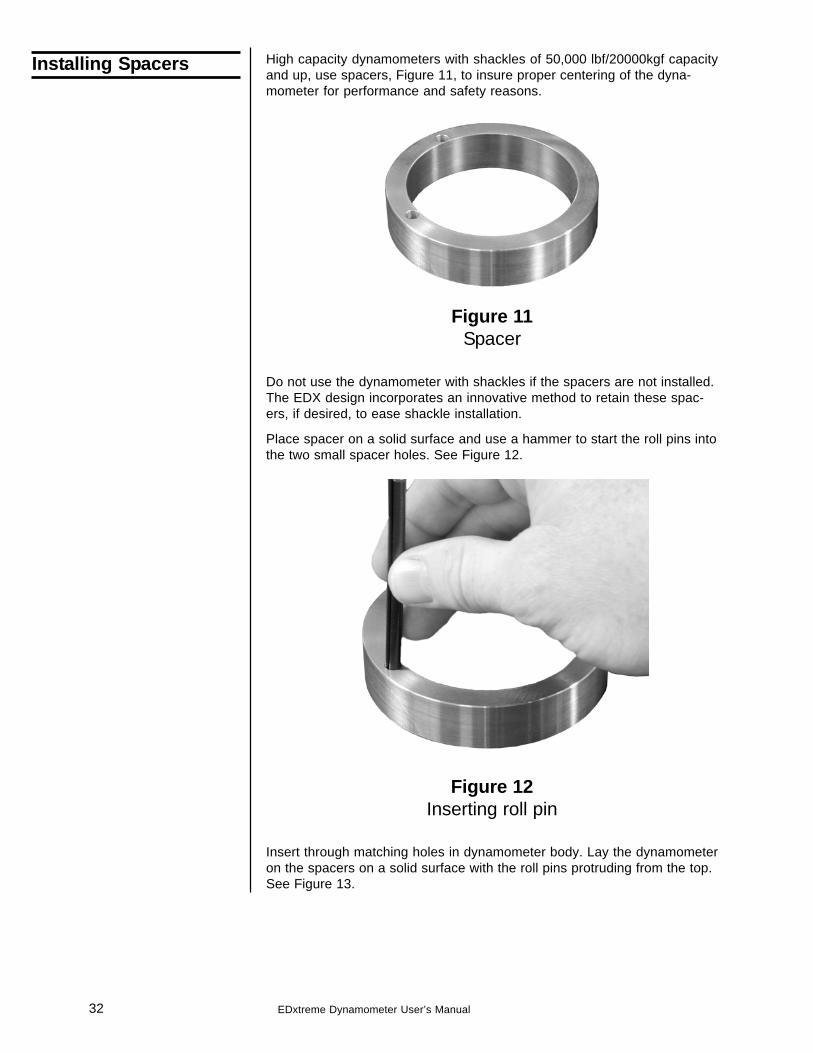
Installing Spacers High capacity dynamometers with shackles of 50,000 lbf/20000kgf capacityand up, use spacers, Figure 11, to insure proper centering of the dyna-mometer for performance and safety reasons.
Figure 11Spacer
Do not use the dynamometer with shackles if the spacers are not installed.The EDX design incorporates an innovative method to retain these spac-ers, if desired, to ease shackle installation.
Place spacer on a solid surface and use a hammer to start the roll pins intothe two small spacer holes. See Figure 12.
Figure 12Inserting roll pin
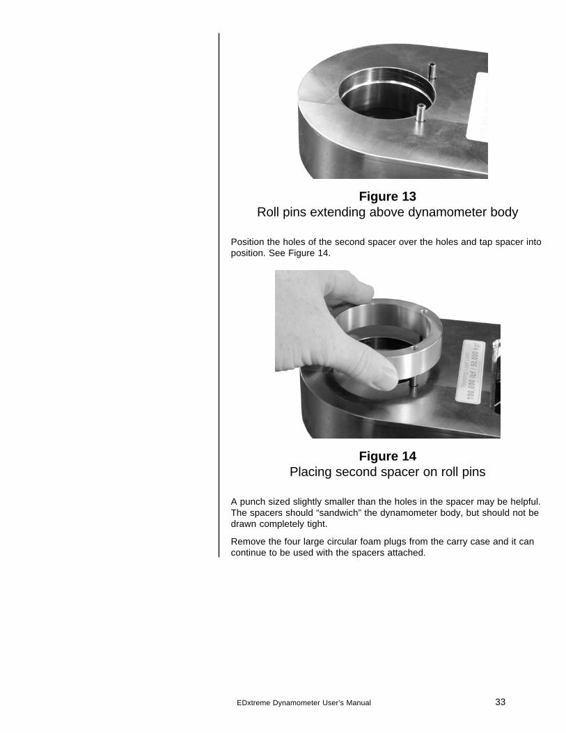
Insert through matching holes in dynamometer body. Lay the dynamometeron the spacers on a solid surface with the roll pins protruding from the top.See Figure 13.
33EDxtreme Dynamometer User’s Manual
Figure 13Roll pins extending above dynamometer body
Position the holes of the second spacer over the holes and tap spacer intoposition. See Figure 14.
Figure 14Placing second spacer on roll pins
A punch sized slightly smaller than the holes in the spacer may be helpful.The spacers should “sandwich” the dynamometer body, but should not bedrawn completely tight.
Remove the four large circular foam plugs from the carry case and it cancontinue to be used with the spacers attached.
34 EDxtreme Dynamometer User’s Manual
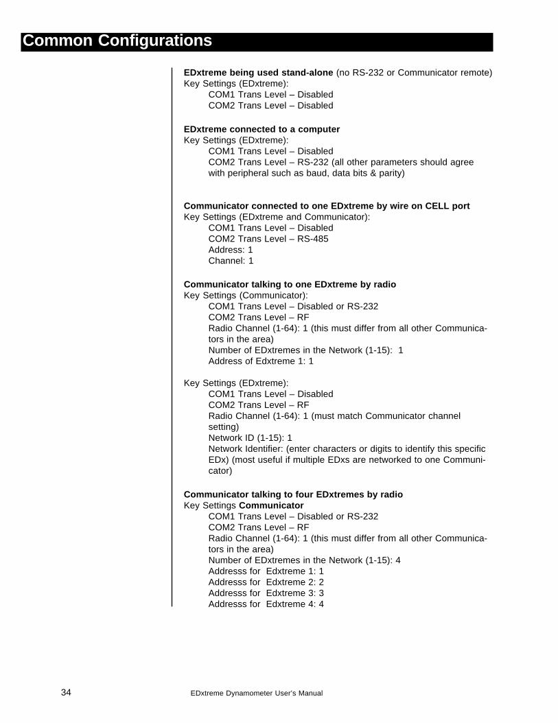
EDxtreme being used stand-alone (no RS-232 or Communicator remote)Key Settings (EDxtreme):
COM1 Trans Level – DisabledCOM2 Trans Level – Disabled
EDxtreme connected to a computerKey Settings (EDxtreme):
COM1 Trans Level – DisabledCOM2 Trans Level – RS-232 (all other parameters should agreewith peripheral such as baud, data bits & parity)
Communicator connected to one EDxtreme by wire on CELL portKey Settings (EDxtreme and Communicator):
COM1 Trans Level – DisabledCOM2 Trans Level – RS-485Address: 1Channel: 1
Communicator talking to one EDxtreme by radioKey Settings (Communicator):
COM1 Trans Level – Disabled or RS-232COM2 Trans Level – RFRadio Channel (1-64): 1 (this must differ from all other Communica-tors in the area)Number of EDxtremes in the Network (1-15): 1Address of Edxtreme 1: 1
Key Settings (EDxtreme):COM1 Trans Level – DisabledCOM2 Trans Level – RFRadio Channel (1-64): 1 (must match Communicator channelsetting)Network ID (1-15): 1Network Identifier: (enter characters or digits to identify this specificEDx) (most useful if multiple EDxs are networked to one Communi-cator)
Communicator talking to four EDxtremes by radioKey Settings Communicator
COM1 Trans Level – Disabled or RS-232COM2 Trans Level – RFRadio Channel (1-64): 1 (this must differ from all other Communica-tors in the area)Number of EDxtremes in the Network (1-15): 4Addresss for Edxtreme 1: 1Addresss for Edxtreme 2: 2Addresss for Edxtreme 3: 3Addresss for Edxtreme 4: 4
Common Configurations
35EDxtreme Dynamometer User’s Manual
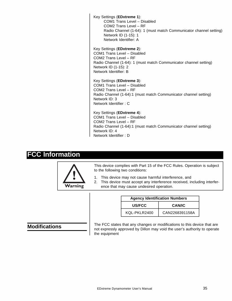
FCC InformationThis device complies with Part 15 of the FCC Rules. Operation is subjectto the following two conditions:
1. This device may not cause harmful interference, and2. This device must accept any interference received, including interfer-
ence that may cause undesired operation.
Agency Identification Numbers
US/FCC CAN/IC
KQL-PKLR2400 CAN2268391158A
The FCC states that any changes or modifications to this device that arenot expressly approved by Dillon may void the user’s authority to operatethe equipment
Modifications
Key Settings (EDxtreme 1):COM1 Trans Level – DisabledCOM2 Trans Level – RFRadio Channel (1-64): 1 (must match Communicator channel setting)Network ID (1-15): 1Network Identifier: A
Key Settings (EDxtreme 2):COM1 Trans Level – DisabledCOM2 Trans Level – RFRadio Channel (1-64): 1 (must match Communicator channel setting)Network ID (1-15): 2Network Identifier: B
Key Settings (EDxtreme 3):COM1 Trans Level – DisabledCOM2 Trans Level – RFRadio Channel (1-64):1 (must match Communicator channel setting)Network ID: 3Network Identifier : C
Key Settings (EDxtreme 4):COM1 Trans Level – DisabledCOM2 Trans Level – RFRadio Channel (1-64):1 (must match Communicator channel setting)Network ID: 4Network Identifier : D
36 EDxtreme Dynamometer User’s Manual
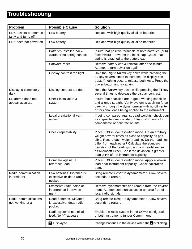
Troubleshooting
SolutionReplace with high quality alkaline batteries
Replace with high quality alkaline batteries
Insure that positive terminals of both batteries (nub)face inward – towards the black cap. Check thatspring is attached to the battery cap.
Remove battery cap & reinstall after one minute.Attempt to turn power on again.
Hold the Right Arrow key down while pressing theF2 key several times to increase the display con-trast. If nothing occurs, release both keys. Press thepower button and try again.
Hold the Arrow key down while pressing the F1 keyseveral times to decrease the display contrast.
Insure that shackles are in good working conditionand aligned straight. Verify system is applying forcedirectly through the dynamometer with no off centeror torsional loads being applied to the instrument.
If being compared against dead-weights, check yourlocal gravitational constant. Use custom units tocompensate or calibrate on-site.
Place EDX in low-resolution mode. Lift an arbitraryweight several times as close to capacity as pos-sible. Record each weight reading. Do the readingsdiffer from each other? Calculate the standarddeviation of the readings using a spreadsheet suchas Microsoft Excel. See if the deviation is greaterthan 0.1% of the instrument capacity.
Place EDX in low-resolution mode. Apply a knownload near instrument capacity. Check calibrationdate.
Bring remote closer to dynamometer. Allow severalseconds to retrain.
Remove dynamometer and remote from the environ-ment. Attempt communications in an area free oflocal radio signals.
Bring remote closer to dynamometer. Allow severalseconds to retrain.
Enable the radio system in the COM2 configurationof both instruments (under Comm menu).
Change batteries in the device when the Y is blinking.
ProblemEDX powers on momen-tarily and turns off
EDX does not power on
Display is completelydark
EDxtreme does notappear accurate
Radio communicationintermittent
Radio communicationsnot working at all
Possible CauseLow battery
Low battery
Batteries installed back-wards or no spring contact
Software reset
Display contrast too light
Display contrast too dark
Check installation &system
Local gravitational vari-ances
Check repeatability
Compare against areference load.
Low batteries. Distance isexcessive or dead-radiopocket
Excessive radio noise orinterference in environ-ment
Dead batteries. Distanceis excessive, dead radiopocket
Radio systems not initial-ized. No “Y” appears.
Y Displayed
37EDxtreme Dynamometer User’s Manual
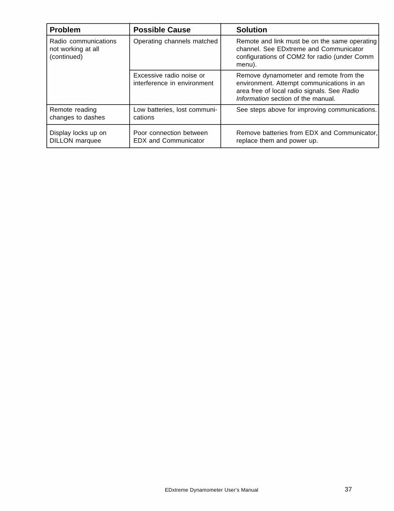
ProblemRadio communicationsnot working at all(continued)
Remote readingchanges to dashes
Display locks up onDILLON marquee
Possible CauseOperating channels matched
Excessive radio noise orinterference in environment
Low batteries, lost communi-cations
Poor connection betweenEDX and Communicator
SolutionRemote and link must be on the same operatingchannel. See EDxtreme and Communicatorconfigurations of COM2 for radio (under Commmenu).
Remove dynamometer and remote from theenvironment. Attempt communications in anarea free of local radio signals. See RadioInformation section of the manual.
See steps above for improving communications.
Remove batteries from EDX and Communicator,replace them and power up.
38 EDxtreme Dynamometer User’s Manual
Torque and Bending
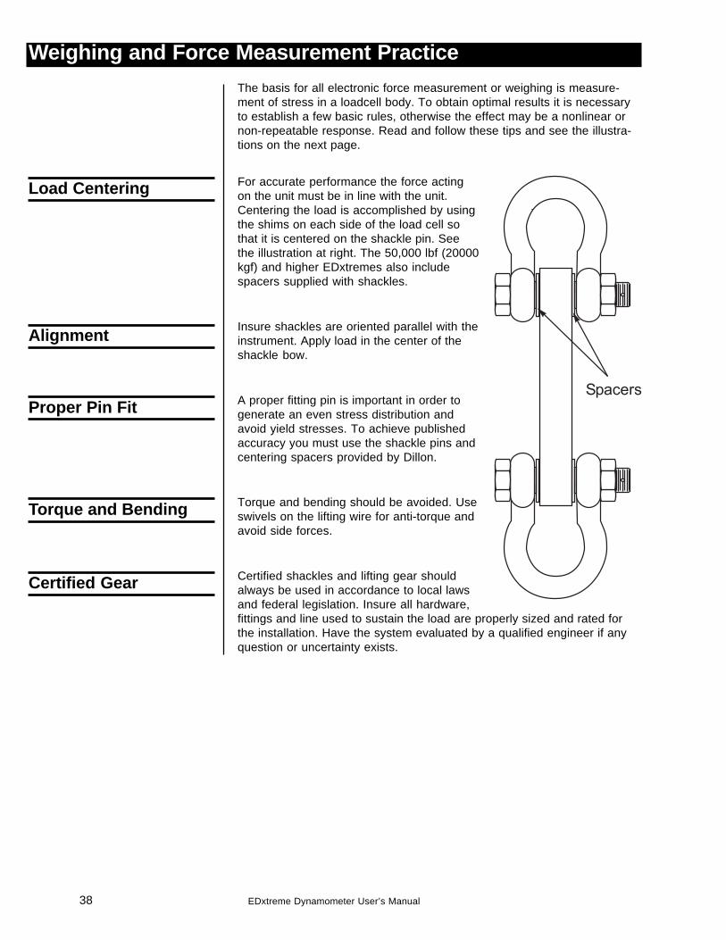
Weighing and Force Measurement PracticeThe basis for all electronic force measurement or weighing is measure-ment of stress in a loadcell body. To obtain optimal results it is necessaryto establish a few basic rules, otherwise the effect may be a nonlinear ornon-repeatable response. Read and follow these tips and see the illustra-tions on the next page.
For accurate performance the force actingon the unit must be in line with the unit.Centering the load is accomplished by usingthe shims on each side of the load cell sothat it is centered on the shackle pin. Seethe illustration at right. The 50,000 lbf (20000kgf) and higher EDxtremes also includespacers supplied with shackles.
Insure shackles are oriented parallel with theinstrument. Apply load in the center of theshackle bow.
A proper fitting pin is important in order togenerate an even stress distribution andavoid yield stresses. To achieve publishedaccuracy you must use the shackle pins andcentering spacers provided by Dillon.
Torque and bending should be avoided. Useswivels on the lifting wire for anti-torque andavoid side forces.
Certified shackles and lifting gear shouldalways be used in accordance to local lawsand federal legislation. Insure all hardware,fittings and line used to sustain the load are properly sized and rated forthe installation. Have the system evaluated by a qualified engineer if anyquestion or uncertainty exists.
Load Centering
Proper Pin Fit
Certified Gear
Alignment
39EDxtreme Dynamometer User’s Manual
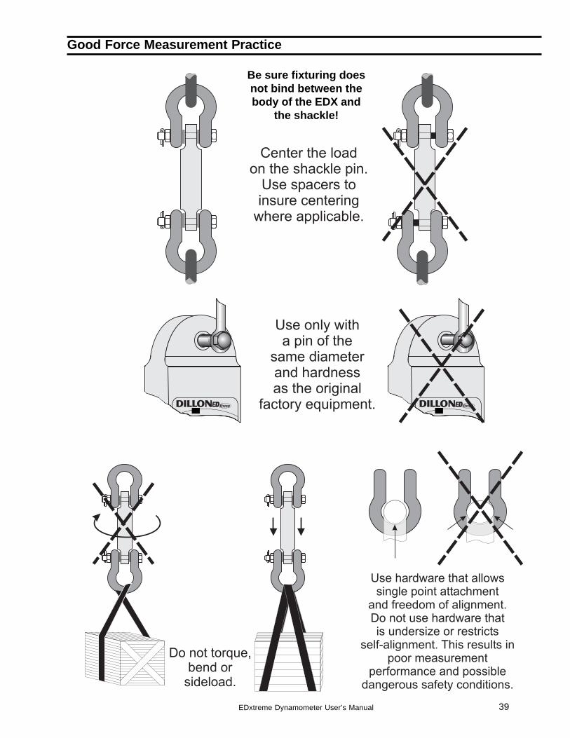
Good Force Measurement Practice
Be sure fixturing doesnot bind between thebody of the EDX and
the shackle!

40 EDxtreme Dynamometer User’s Manual

41EDxtreme Dynamometer User’s Manual

42 EDxtreme Dynamometer User’s Manual

43EDxtreme Dynamometer User’s Manual

DillonA division of Weigh-Tronix Inc.1000 Armstrong Dr.Fairmont, MN 56031 USATelephone: 507-238-4461Facsimile: 507-238-8258e-mail: [email protected]
Force Measurement Products & Systems