Embed Size (px)
Citation preview
D372-98-880Issue E Original
Instruction Manual
PC Interface Kits
Description Item Number
Desktop PC Interface Kit D372-18-100
PCMCIA Laptop PC Interface Kit D372-17-000

This page has been intentionally left blank.

© Edwards Limited 2008. All rights reserved. Page iEdwards and the Edwards logo are trademarks of Edwards Limited.
ContentsD372-98-880 Issue E
Contents
Section Page
1 Introduction ....................................................................................... 1
1.1 Scope and definitions ................................................................................................... 11.2 Description ................................................................................................................ 11.3 Networkable system and network connections ..................................................................... 21.4 PCLTA (Desktop PC Interface Kit) ..................................................................................... 21.5 PCMCIA card (PCMCIA Laptop PC Interface Kit) ..................................................................... 2
2 Technical Data .................................................................................... 3
3 Installation ......................................................................................... 5
3.1 Unpack and inspect ...................................................................................................... 53.2 Install and connect the Desktop PC Interface Kit ................................................................... 53.3 Install and connect the PCMCIA Laptop PC Interface Kit .......................................................... 6
4 Operation .......................................................................................... 7
5 Maintenance ....................................................................................... 9
5.1 Inspect the electrical connections .................................................................................... 95.2 Communications problems ............................................................................................. 95.2.1 Fault finding .............................................................................................................. 95.2.2 CONFIG.SYS device driver lines ........................................................................................ 9
6 Storage and Disposal ........................................................................... 11
6.1 Storage ...................................................................................................................116.2 Disposal ...................................................................................................................11
7 Spares and Accessories ........................................................................ 13
7.1 Introduction .............................................................................................................137.2 Spares .....................................................................................................................137.3 Accessories ...............................................................................................................13
For return of equipment, complete the HS Forms at the end of this manual.
Illustrations
Figure Page1 Schematic Diagram of the PC Interface Kit Electrical Connections .............................................. 4
cg/6
012/
10/0
8
D372-98-880 Issue E
Page ii © Edwards Limited 2008. All rights reserved.Edwards and the Edwards logo are trademarks of Edwards Limited.
Contents
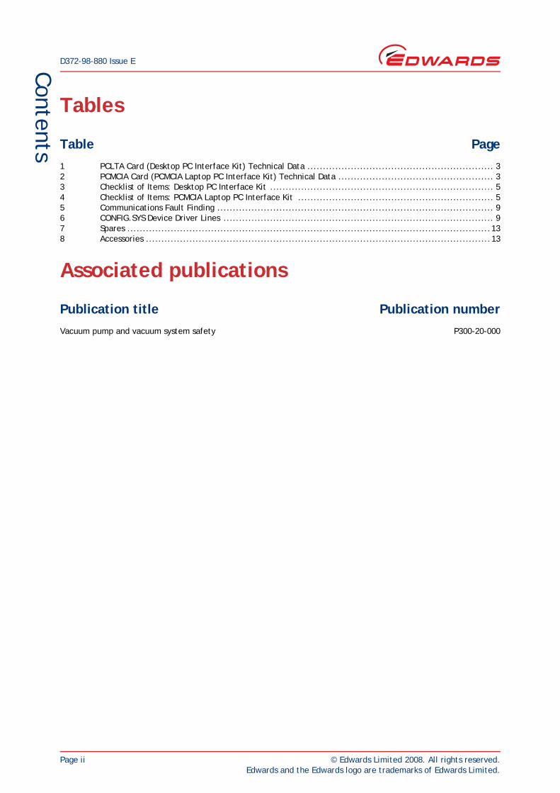
Tables
Table Page1 PCLTA Card (Desktop PC Interface Kit) Technical Data ............................................................ 32 PCMCIA Card (PCMCIA Laptop PC Interface Kit) Technical Data .................................................. 33 Checklist of Items: Desktop PC Interface Kit ........................................................................ 54 Checklist of Items: PCMCIA Laptop PC Interface Kit ............................................................... 55 Communications Fault Finding ......................................................................................... 96 CONFIG.SYS Device Driver Lines ....................................................................................... 97 Spares .....................................................................................................................138 Accessories ...............................................................................................................13
Associated publications
Publication title Publication numberVacuum pump and vacuum system safety P300-20-000
© Edwards Limited 2008. All rights reserved. Page 1Edwards and the Edwards logo are trademarks of Edwards Limited.
IntroductionD372-80-880 Issue B
1 Introduction1.1 Scope and definitions
This manual provides installation, operation and maintenance instructions for the Edwards PC Interface Kits. You must use the PC Interface Kits as specified in the manual.
Read this manual before you install and operate the PC Interface Kits. Important safety information is highlighted as WARNING and CAUTION instructions; you must obey these instructions. The use of WARNINGS and CAUTIONS is defined below.
CAUTIONCautions are given where failure to observe the instruction could result in damage to the equipment, associated equipment and process
The following IEC warning labels appear on the pump:
The units used throughout this manual conform to the SI international system of units of measurement.
1.2 Description
Install a PC Interface Kit on your PC (personal computer) to allow your PC to communicate with a BOC Edwards networkable system or with a BOC Edwards network, when you want to use the BOC Edwards SEM (Single Equipment Monitor) or FabWorks software on your PC to monitor and to control the operation of one or more networkable systems.
BOC Edwards networkable systems include dry pumping systems and abatement systems.
Two types of PC Interface Kit are available:
The Desktop PC Interface Kit has a PCLTA (PC LonTalk Adaptor) card, designed to be installed inside your desktop PC.
The PCMCIA Laptop PC Interface Kit has a PCC-10 PCMCIA (PC Memory Card International Association) card, designed to be fitted to the PCMCIA port of your laptop PC.
WARNING
Warnings are given where failure to observe the instruction could result in injury or death to people.
Warning - refer to accompanying documentation.
Warning - Edwards offer European customers a recycling service.
D372-80-880 Issue B
Page 2 © Edwards Limited 2008. All rights reserved.Edwards and the Edwards logo are trademarks of Edwards Limited.
Introduction
1.3 Networkable system and network connections
Refer to Figure 1 which shows a schematic diagram of the electrical connections of the PC Interface Kit to a networkable system or to a network. You can use one of the following methods to connect the PC Interface Kit:
Connect the PC Interface Kit directly to a networkable system, as shown in detail A.
Connect the PC Interface Kit to a network, through a PC network connection, as shown in details B and C.
Connect the PC Interface Kit to a network, through a Network Interface Module (NIM), as shown in details D and E.
1.4 PCLTA (Desktop PC Interface Kit)
The PCLTA is a circuit board designed to be installed inside a desktop PC, and to be connected to the ISA bus of the PC.
1.5 PCMCIA card (PCMCIA Laptop PC Interface Kit)
The PCMCIA card is supplied with the following:
A TP78 adaptor module, which you will connect to the PCMCIA card.
An XLR adaptor cable, to connect the adaptor module to a networkable system or a PC network connection.
SEM (Single Equipment Monitor) software.
© Edwards Limited 2008. All rights reserved. Page 3Edwards and the Edwards logo are trademarks of Edwards Limited.
Technical Data
D372-80-880 Issue B
2 Technical Data
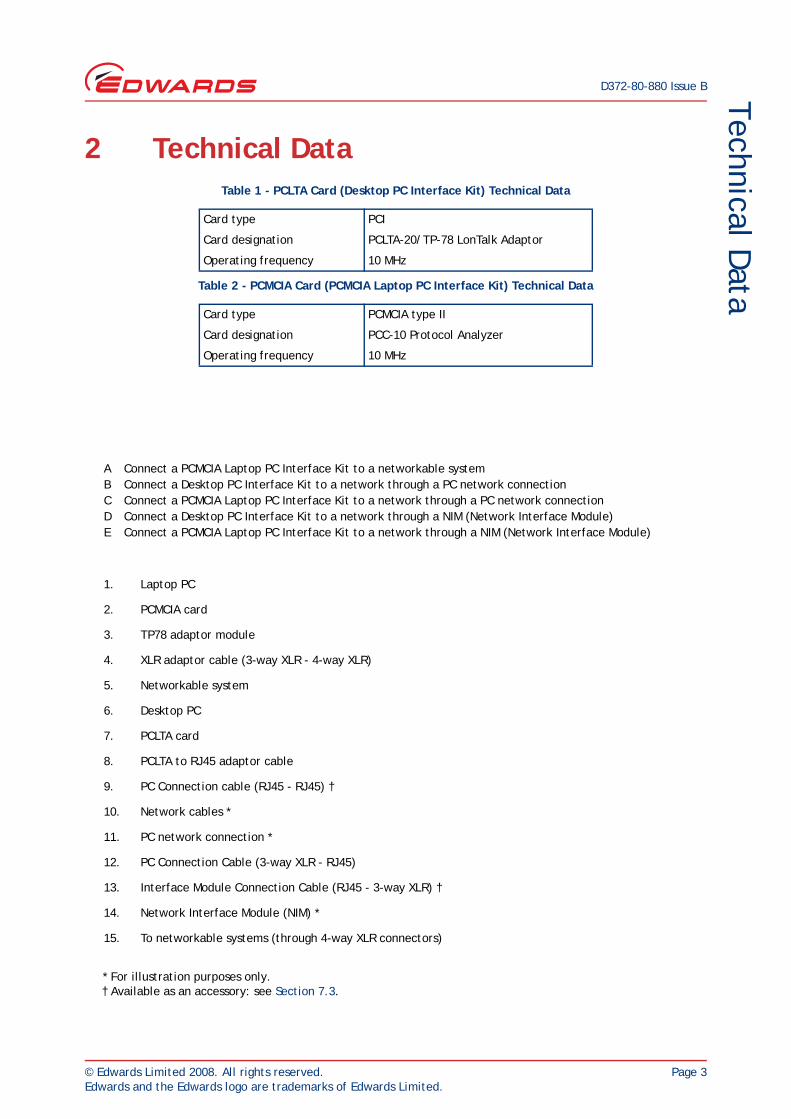
A Connect a PCMCIA Laptop PC Interface Kit to a networkable systemB Connect a Desktop PC Interface Kit to a network through a PC network connectionC Connect a PCMCIA Laptop PC Interface Kit to a network through a PC network connectionD Connect a Desktop PC Interface Kit to a network through a NIM (Network Interface Module)E Connect a PCMCIA Laptop PC Interface Kit to a network through a NIM (Network Interface Module)
1. Laptop PC
2. PCMCIA card
3. TP78 adaptor module
4. XLR adaptor cable (3-way XLR - 4-way XLR)
5. Networkable system
6. Desktop PC
7. PCLTA card
8. PCLTA to RJ45 adaptor cable
9. PC Connection cable (RJ45 - RJ45) †
10. Network cables *
11. PC network connection *
12. PC Connection Cable (3-way XLR - RJ45)
13. Interface Module Connection Cable (RJ45 - 3-way XLR) †
14. Network Interface Module (NIM) *
15. To networkable systems (through 4-way XLR connectors)
* For illustration purposes only.† Available as an accessory: see Section 7.3.
Table 1 - PCLTA Card (Desktop PC Interface Kit) Technical Data
Card type PCI
Card designation PCLTA-20/TP-78 LonTalk Adaptor
Operating frequency 10 MHz
Table 2 - PCMCIA Card (PCMCIA Laptop PC Interface Kit) Technical Data
Card type PCMCIA type II
Card designation PCC-10 Protocol Analyzer
Operating frequency 10 MHz

D372-80-880 Issue B
Page 4 © Edwards Limited 2008. All rights reserved.Edwards and the Edwards logo are trademarks of Edwards Limited.
Technical Data
Figure 1 - Schematic Diagram of the PC Interface Kit Electrical Connections
© Edwards Limited 2008. All rights reserved. Page 5Edwards and the Edwards logo are trademarks of Edwards Limited.
InstallationD372-80-880 Issue B
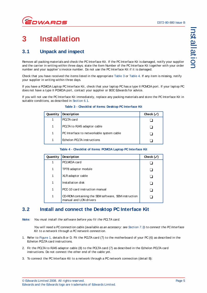
3 Installation3.1 Unpack and inspect
Remove all packing materials and check the PC Interface Kit. If the PC Interface Kit is damaged, notify your supplier and the carrier in writing within three days; state the Item Number of the PC Interface Kit together with your order number and your supplier’s invoice number. Do not use the PC Interface Kit if it is damaged.
Check that you have received the items listed in the appropriate Table 3 or Table 4. If any item is missing, notify your supplier in writing within three days.
If you have a PCMCIA Laptop PC Interface Kit, check that your laptop PC has a type II PCMCIA port. If your laptop PC does not have a type II PCMCIA port, contact your supplier or BOC Edwards for advice.
If you will not use the PC Interface Kit immediately, replace any packing materials and store the PC Interface Kit in suitable conditions, as described in Section 6.1.
3.2 Install and connect the Desktop PC Interface Kit
Note: You must install the software before you fit the PCLTA card.
You will need a PC connection cable (available as an accessory: see Section 7.3) to connect the PC Interface Kit to a network through a PC network connection.
1. Refer to Figure 1, details B or D. Fit the PCLTA card (7) to the motherboard of your PC (6) as described in the Echelon PCLTA card instructions.
2. Fit the PCLTA to RJ45 adaptor cable (8) to the PCLTA card (7) as described in the Echelon PCLTA card instructions. Do not connect the other end of the cable yet.
3. To connect the PC Interface Kit to a network through a PC network connection (detail B):
Table 3 - Checklist of Items: Desktop PC Interface Kit
Quantity Description Check ( )
1 PCLTA card
1 PCLTA to RJ45 adaptor cable
1 PC Interface to networkable system cable
1 Echelon PCLTA instructions
Table 4 - Checklist of Items: PCMCIA Laptop PC Interface Kit
Quantity Description Check ( )
1 PCLMCIA card
1 TP78 adaptor module
1 XLR adaptor cable
1 Installation disk
1 PCC-10 card instruction manual
1 CD-ROM containing the SEM software, SEM instruction manual and LON drivers
D372-80-880 Issue B
Page 6 © Edwards Limited 2008. All rights reserved.Edwards and the Edwards logo are trademarks of Edwards Limited.
Installation
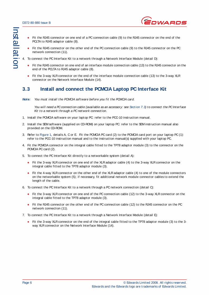
Fit the RJ45 connector on one end of a PC connection cable (9) to the RJ45 connector on the end of the PCLTA to RJ45 adaptor cable (8).
Fit the RJ45 connector on the other end of the PC connection cable (9) to the RJ45 connector on the PC network connection (11).
4. To connect the PC Interface Kit to a network through a Network Interface Module (detail D):
Fit the RJ45 connector on one end of an interface module connection cable (13) to the RJ45 connector on the end of the PCLTA to RJ45 adaptor cable (8).
Fit the 3-way XLR connector on the end of the interface module connection cable (13) to the 3-way XLR connector on the Network Interface Module (14).
3.3 Install and connect the PCMCIA Laptop PC Interface Kit
Note: You must install the PCMCIA software before you fit the PCMCIA card.
You will need a PC connection cable (available as an accessory: see Section 7.3) to connect the PC Interface Kit to a network through a PC network connection.
1. Install the PCMCIA software on your laptop PC: refer to the PCC-10 instruction manual.
2. Install the SEM software (supplied on CD-ROM) on your laptop PC: refer to the SEM instruction manual also provided on the CD-ROM.
3. Refer to Figure 1, details A, C or E. Fit the PCMCIA PC card (2) to the PCMCIA card port on your laptop PC (1): refer to the PCC-10 instruction manual and to the instruction manual(s) supplied with your laptop PC.
4. Fit the PCMCIA connector on the integral cable fitted to the TP78 adaptor module (3) to the connector on the PCMCIA PC card (2).
5. To connect the PC Interface Kit directly to a networkable system (detail A):
Fit the 3-way XLR connector on one end of the XLR adaptor cable (4) to the 3-way XLR connector on the integral cable fitted to the TP78 adaptor module (3).
Fit the 4-way XLR connector on the other end of the XLR adaptor cable (4) to one of the module connectors on the networkable system (5); if necessary, fit additional network module connector cables to extend the length of the cable.
6. To connect the PC Interface Kit to a network through a PC network connection (detail C):
Fit the 3-way XLR connector on one end of the PC connection cable (12) to the 3-way XLR connector on the integral cable fitted to the TP78 adaptor module (3).
Fit the RJ45 connector on the other end of the PC connection cable (12) to the RJ45 connector on the PC network connection (11).
7. To connect the PC Interface Kit to a network through a Network Interface Module (detail E):
Fit the 3-way XLR connector on the end of the integral cable fitted to the TP78 adaptor module (3) to the 3-way XLR connector on the Network Interface Module (14).

© Edwards Limited 2008. All rights reserved. Page 7Edwards and the Edwards logo are trademarks of Edwards Limited.
Operation
D372-80-880 Issue B
4 OperationThe PC Interface will operate as soon as the PC is switched on.

D372-80-880 Issue B
Page 8 © Edwards Limited 2008. All rights reserved.Edwards and the Edwards logo are trademarks of Edwards Limited.
This page has been intentionally left blank.
© Edwards Limited 2008. All rights reserved. Page 9Edwards and the Edwards logo are trademarks of Edwards Limited.
Maintenance
D372-80-880 Issue B
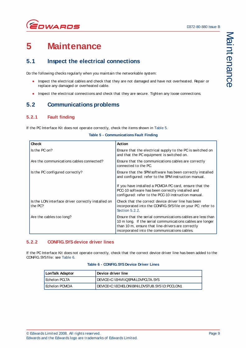
5 Maintenance5.1 Inspect the electrical connections
Do the following checks regularly when you maintain the networkable system:
Inspect the electrical cables and check that they are not damaged and have not overheated. Repair or replace any damaged or overheated cable.
Inspect the electrical connections and check that they are secure. Tighten any loose connections.
5.2 Communications problems
5.2.1 Fault finding
If the PC Interface Kit does not operate correctly, check the items shown in Table 5.
5.2.2 CONFIG.SYS device driver lines
If the PC Interface Kit does not operate correctly, check that the correct device driver line has been added to the CONFIG.SYS file: see Table 6.
Table 5 - Communications Fault Finding
Check Action
Is the PC on? Ensure that the electrical supply to the PC is switched on and that the PC equipment is switched on.
Are the communications cables connected? Ensure that the communications cables are correctly connected to the PC.
Is the PC configured correctly? Ensure that the SPM software has been correctly installed and configured: refer to the SPM instruction manual.
If you have installed a PCMCIA PC card, ensure that the PCC-10 software has been correctly installed and configured: refer to the PCC-10 instruction manual.
Is the LON interface driver correctly installed on the PC?
Check that the correct device driver line has been incorporated into the CONFIG.SYS file on your PC: refer to Section 5.2.2.
Are the cables too long? Ensure that the serial communications cables are less than 10 m long. If the serial communications cables are longer than 10 m, ensure that line-drivers are correctly incorporated into the communications cables.
Table 6 - CONFIG.SYS Device Driver Lines
LonTalk Adaptor Device driver line
Echelon PCLTA DEVICE=C:\EHVI\IQSPM\LDVPCLTA.SYS
Echelon PCMCIA DEVICE=C:\ECHELON\BIN\LDVSTUB.SYS \D:PCCLON1

D372-80-880 Issue B
Page 10 © Edwards Limited 2008. All rights reserved.Edwards and the Edwards logo are trademarks of Edwards Limited.
This page has been intentionally left blank.
© Edwards Limited 2008. All rights reserved. Page 11Edwards and the Edwards logo are trademarks of Edwards Limited.
Storage and Disposal
D372-80-880 Issue B
6 Storage and Disposal6.1 Storage
Replace any protective packing materials and store the PC Interface Kit in clean dry conditions.
When required for use, install the PC Interface Kit as described in Section 3.
6.2 Disposal
Dispose of the PC Interface Kit and any components safely in accordance with all local and national safety and environmental requirements.

D372-80-880 Issue B
Page 12 © Edwards Limited 2008. All rights reserved.Edwards and the Edwards logo are trademarks of Edwards Limited.
This page has been intentionally left blank.
© Edwards Limited 2008. All rights reserved. Page 13Edwards and the Edwards logo are trademarks of Edwards Limited.
Spares and AccessoriesD372-80-880 Issue B
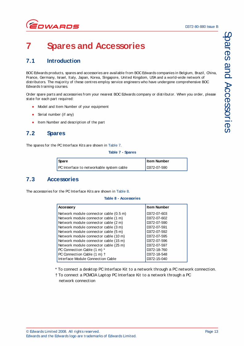
7 Spares and Accessories7.1 Introduction
BOC Edwards products, spares and accessories are available from BOC Edwards companies in Belgium, Brazil, China, France, Germany, Israel, Italy, Japan, Korea, Singapore, United Kingdom, USA and a world-wide network of distributors. The majority of these centres employ service engineers who have undergone comprehensive BOC Edwards training courses.
Order spare parts and accessories from your nearest BOC Edwards company or distributor. When you order, please state for each part required:
Model and Item Number of your equipment
Serial number (if any)
Item Number and description of the part
7.2 Spares
The spares for the PC Interface Kits are shown in Table 7.
7.3 Accessories
The accessories for the PC Interface Kits are shown in Table 8.
* To connect a desktop PC Interface Kit to a network through a PC network connection.† To connect a PCMCIA Laptop PC Interface Kit to a network through a PC network connection
Table 7 - Spares
Spare Item Number
PC Interface to networkable system cable D372-07-590
Table 8 - Accessories
Accessory Item Number
Network module connector cable (0.5 m)Network module connector cable (1 m)Network module connector cable (2 m)Network module connector cable (3 m)Network module connector cable (5 m)Network module connector cable (10 m)Network module connector cable (15 m)Network module connector cable (25 m)PC Connection Cable (1 m) *PC Connection Cable (1 m) †Interface Module Connection Cable
D372-07-603D372-07-602D372-07-590D372-07-591D372-07-592D372-07-595D372-07-596D372-07-597D372-18-760D372-18-548D372-15-040

D372-80-880 Issue B
Page 14 © Edwards Limited 2008. All rights reserved.Edwards and the Edwards logo are trademarks of Edwards Limited.
This page has been intentionally left blank.