Embed Size (px)
Citation preview
SANDIA REPORT SAND2013-9718 Unlimited Release Printed November 2013
EDS V26 Containment Vessel Explosive Qualification Test Report Robert Crocker, Brent Haroldsen, Jerry Stofleth Prepared by Sandia National Laboratories Albuquerque, New Mexico 87185 and Livermore, California 94550 Sandia National Laboratories is a multi-program laboratory managed and operated by Sandia Corporation, a wholly owned subsidiary of Lockheed Martin Corporation, for the U.S. Department of Energy's National Nuclear Security Administration under contract DE-AC04-94AL85000. Approved for public release; further dissemination unlimited.
2
Issued by Sandia National Laboratories, operated for the United States Department of Energy by Sandia Corporation. NOTICE: This report was prepared as an account of work sponsored by an agency of the United States Government. Neither the United States Government, nor any agency thereof, nor any of their employees, nor any of their contractors, subcontractors, or their employees, make any warranty, express or implied, or assume any legal liability or responsibility for the accuracy, completeness, or usefulness of any information, apparatus, product, or process disclosed, or represent that its use would not infringe privately owned rights. Reference herein to any specific commercial product, process, or service by trade name, trademark, manufacturer, or otherwise, does not necessarily constitute or imply its endorsement, recommendation, or favoring by the United States Government, any agency thereof, or any of their contractors or subcontractors. The views and opinions expressed herein do not necessarily state or reflect those of the United States Government, any agency thereof, or any of their contractors. Printed in the United States of America. This report has been reproduced directly from the best available copy. Available to DOE and DOE contractors from U.S. Department of Energy Office of Scientific and Technical Information P.O. Box 62 Oak Ridge, TN 37831 Telephone: (865) 576-8401 Facsimile: (865) 576-5728 E-Mail: [email protected] Online ordering: http://www.osti.gov/bridge Available to the public from U.S. Department of Commerce National Technical Information Service 5285 Port Royal Rd. Springfield, VA 22161 Telephone: (800) 553-6847 Facsimile: (703) 605-6900 E-Mail: [email protected] Online order: http://www.ntis.gov/help/ordermethods.asp?loc=7-4-0#online
3
SAND2013-9718 Unlimited Release
Printed November 2013
EDS V26 Containment Vessel Explosive Test Report
Robert Crocker, Brent Haroldsen, Jerry Stofleth Sandia National Laboratories P.O. Box 5800 Albuquerque, New Mexico 87185
Abstract The V26 containment vessel was procured by the Project Manager, Non-Stockpile Chemical Materiel (PMNSCM) as a replacement vessel for use on the P2 Explosive Destruction Systems. It is the second EDS vessel to be fabricated under Code Case 2564 of the ASME Boiler and Pressure Vessel Code, which provides rules for the design of impulsively loaded vessels. The explosive rating for the vessel, based on the Code Case, is nine (9) pounds TNT-equivalent for up to 637 detonations. This report documents the results of a two explosive tests that were done on the vessel at Sandia National Laboratories in Albuquerque New Mexico in July 2013 to qualify the vessel for explosive use. The explosive tests consisted of a 9 pound bare charge of Composition C-4 (equivalent to 11.25 pounds TNT) and a 7.2 pound bare charge of Composition C-4 (equivalent to 9 pounds of TNT). All vessel acceptance criteria were met.

4
This page intentionally left blank.
5
Contents EDS V26 Containment Vessel Explosive Test Report ................................................................... 3
1 Background ............................................................................................................................. 7
2 Test Objectives and Description ............................................................................................. 9
3 Vessel Design Basis .............................................................................................................. 11
4 Vessel Qualification .............................................................................................................. 13
5 Conclusions ........................................................................................................................... 17
6 References ............................................................................................................................. 18

6
This page intentionally left blank.
7
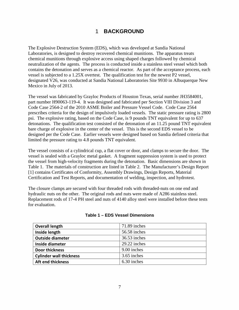
1 BACKGROUND The Explosive Destruction System (EDS), which was developed at Sandia National Laboratories, is designed to destroy recovered chemical munitions. The apparatus treats chemical munitions through explosive access using shaped charges followed by chemical neutralization of the agents. The process is conducted inside a stainless steel vessel which both contains the detonation and serves as a chemical reactor. As part of the acceptance process, each vessel is subjected to a 1.25X overtest. The qualification test for the newest P2 vessel, designated V26, was conducted at Sandia National Laboratories Site 9930 in Albuquerque New Mexico in July of 2013. The vessel was fabricated by Grayloc Products of Houston Texas, serial number JH3584001, part number H90063-119-4. It was designed and fabricated per Section VIII Division 3 and Code Case 2564-2 of the 2010 ASME Boiler and Pressure Vessel Code. Code Case 2564 prescribes criteria for the design of impulsively loaded vessels. The static pressure rating is 2800 psi. The explosive rating, based on the Code Case, is 9 pounds TNT equivalent for up to 637 detonations. The qualification test consisted of the detonation of an 11.25 pound TNT equivalent bare charge of explosive in the center of the vessel. This is the second EDS vessel to be designed per the Code Case. Earlier vessels were designed based on Sandia defined criteria that limited the pressure rating to 4.8 pounds TNT equivalent. The vessel consists of a cylindrical cup, a flat cover or door, and clamps to secure the door. The vessel is sealed with a Grayloc metal gasket. A fragment suppression system is used to protect the vessel from high-velocity fragments during the detonation. Basic dimensions are shown in Table 1. The materials of construction are listed in Table 2. The Manufacturer’s Design Report [1] contains Certificates of Conformity, Assembly Drawings, Design Reports, Material Certification and Test Reports, and documentation of welding, inspection, and hydrotest. The closure clamps are secured with four threaded rods with threaded-nuts on one end and hydraulic nuts on the other. The original rods and nuts were made of A286 stainless steel. Replacement rods of 17-4 PH steel and nuts of 4140 alloy steel were installed before these tests for evaluation.
Table 1 – EDS Vessel Dimensions
Overall length 71.89 inches Inside length 56.58 inches Outside diameter 36.53 inches Inside diameter 29.22 inches Door thickness 9.00 inches Cylinder wall thickness 3.65 inches Aft end thickness 6.30 inches
8
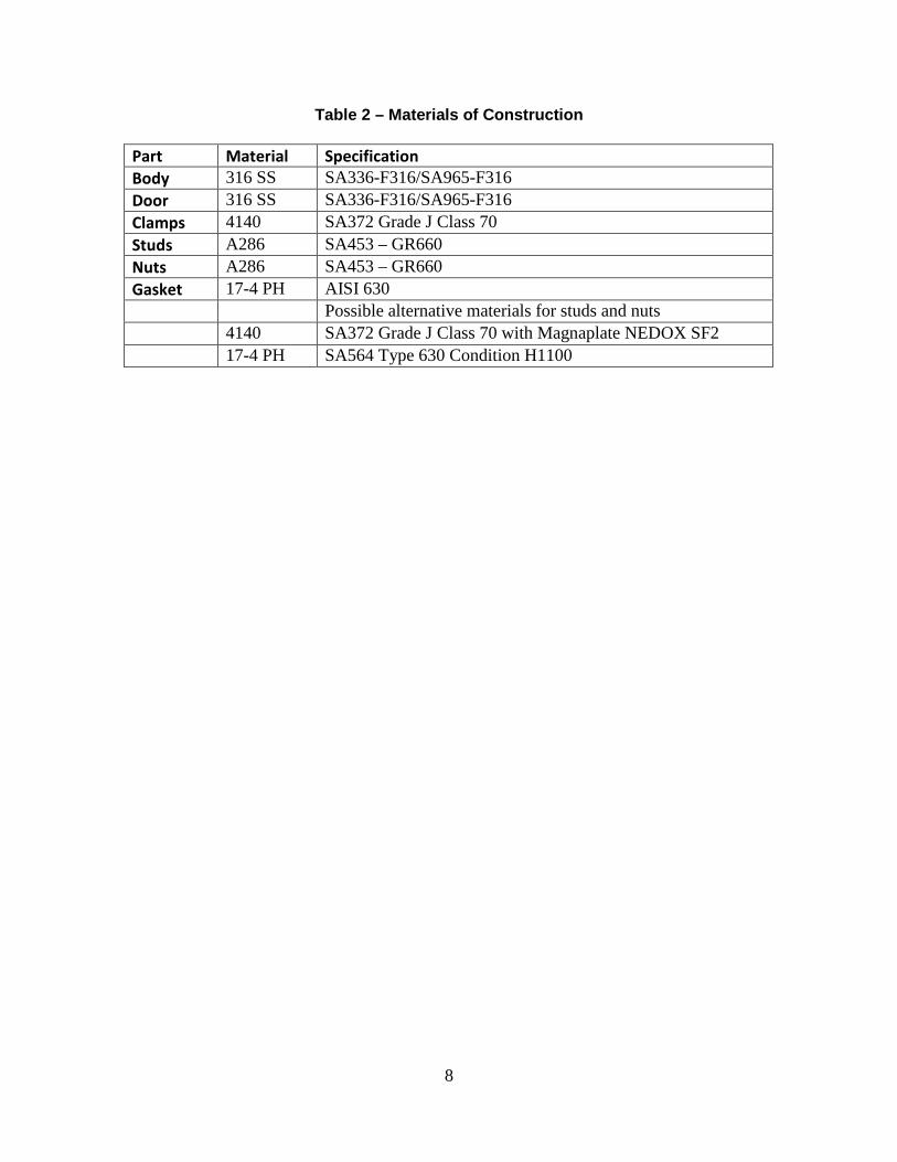
Table 2 – Materials of Construction
Part Material Specification Body 316 SS SA336-F316/SA965-F316 Door 316 SS SA336-F316/SA965-F316 Clamps 4140 SA372 Grade J Class 70 Studs A286 SA453 – GR660 Nuts A286 SA453 – GR660 Gasket 17-4 PH AISI 630 Possible alternative materials for studs and nuts 4140 SA372 Grade J Class 70 with Magnaplate NEDOX SF2 17-4 PH SA564 Type 630 Condition H1100
9
2 TEST OBJECTIVES AND DESCRIPTION The objective of the test was to qualify the vessel for its intended use by subjecting it to a 1.25 times overtest. The criteria for success are that the measured strains do not exceed the calculated strains from the vessel analysis, there is no significant additional plastic strain on subsequent tests at the rated design load (shakedown), and there is no significant damage to the vessel and attached hardware that affect form, fit, or function. Testing of the V25 Vessel in 2011 established a precedent for testing V26 [2]. As with V25, two tests were performed to satisfy this objective. The first test used 9 pounds of Composition C-4 (11.25 lbs. TNT-equivalent), which is 125 percent of the design basis load. The second test used 7.2 pounds of Composition C-4 (9 lbs. TNT-equivalent) which is 100 percent of the design basis load. The first test provided the required overtest while the second test served to demonstrate shakedown and the absence of additional plastic deformation. Unlike the V25 vessel, which was mounted in a shipping cradle during testing, the V26 vessel was mounted on the EDS P2U3 trailer prior to testing. Visual inspections of the EDS vessel, surroundings, and diagnostics were completed before and after each test event. This visual inspection included analyzing the seals, fittings, and interior surfaces of the EDS vessel and documenting any abnormalities or damages. Photographs were used to visually document vessel conditions and findings before and after each test event.

10
This page intentionally left blank.
11
3 VESSEL DESIGN BASIS The design impulse for the vessel, as defined in the User Design Specification, is a centrally-located, cylindrically-shaped, 9 pound bare charge of TNT, with a length-to-diameter aspect ratio between 1.5 and 2, simultaneously detonated at two points near the two ends of the charge. The aspect ratio and detonator locations were strictly arbitrary, but they have an effect on the vessel loads so it was considered important to document what was actually analyzed and tested. The loads on an impulsively loaded vessel depend on several factors including the quantity of explosives, the location of the explosives within the vessel, the type of explosives, the shape of the charge, the number and location of detonators, the relative timing if there are multiple charges or multiple points of detonation, and the location of obstructions such as munitions or fragment barriers that can mitigate the blast. In an actual EDS operation, there can be multiple explosive charges dispersed around the vessel and detonated at slightly different times. There are also obstacles such as munition housings and the fragment suppression system that can dissipate or redirect the pressure shocks. It is not feasible to model and analyze every possible configuration so the single bare charge was chosen as a worst case loading condition. Table 3 shows the calculated equivalent plastic strains at key locations resulting for the detonation of bare, centrally-located explosive charges between 5 and 10 pounds TNT equivalent. The design limits in the Code Case for the in-plane equivalent plastic strain of the base metal are:
• membrane strain < 0.2%, • accumulated bending strain < 2%, and • peak strain < 5%,
where membrane strain is defined to be εm = 0.5 (εint + εext ) (1) and bending strain is defined to be εb = 0.5 (εint - εext ) (2) The membrane design limit (εm < 0.2%) is intended to protect the vessel against tensile failure due to ductile rupture. The bending strain limit (εb < 2%) is intended to prevent excessive distortion during cyclic loading, such as that from plastic ratcheting where the plastic strains increase with repeated cycles. Since equivalent plastic strain is semi-positive definite, it does not give a clear indication whether the walls are undergoing membrane or bending phenomena. Therefore, the signs of the component strains perpendicular to the symmetry plane are used. Using the convention that positive is tension and negative is compression, membrane behavior (tension across entire thickness) occurs at the cylinder wall and bending behavior (compression on one side and tension on the other) occurs at the aft end. For this reason, in calculating εb, the equivalent strain on the interior is entered as a negative number. The limiting criterion for the EDS vessel is membrane strain in the cylindrical wall. With 9 pounds of TNT, εm is 0.195%, just below the design limit of 0.2%. The vessel life is based on a fatigue analysis which is documented in the design report.
12
Table 3: Calculated Equivalent Plastic Strains (percent)
Explosive load Wall Aft End
interior center exterior εm interior center exterior εb 5 lbs. 0.0 0.00 0.0 0 (-)0.02 0.0 0.02 0.02 8 lbs. 0.18 0.03 0.06 0.12 (-)0.43 0.0 0.32 0.375 9 lbs. 0.26 0.07 0.13 0.195 (-)0.51 0.0 0.47 0.49
10 lbs. 0.34 0.10 0.17 0.255 (-)0.72 0.0 0.72 0.72
13
4 VESSEL QUALIFICATION The first explosive test, conducted on July 11, 2013, consisted of a 9 pound (11.25 pound TNT equivalent), cylindrical charge of Composition C-4 (Figure 1). The explosive was packed into a 5-inch inside diameter cardboard shipping tube to a density of 1.6g/cc. A Reynolds, RP-1, Exploding Bridgewire (EBW) detonator was placed at both ends. The two detonators were detonated simultaneously (within 200ns). A 1/4 inch thick disk of 10lb./ft3Polyurethane was placed at the midpoint of the cylinder. The intent of the disk was to prevent radial jetting that occurs when detonation fronts from both ends of the cylinder meet. The total length of the explosive and disk was 8.19 inches. The thickness of the cardboard tube was 1/8 inch. The charge was located at dead center along the length and diameter and held with 2-inch thick sheets of Styrofoam insulation board as shown in Figure 2. The small blast plates were installed on the door, but the large plate was not. There was no valve panel. A valve was attached to each of the three ports on the vessel door. The valve on the bottom port was used to fill and vent the vessel.
Figure 1: 9 lb. C-4 Charge (11.25 lb. TNT eq)
Figure 2: 11.25 lb. TNT eq Charge in Vessel
The second explosive test, conducted on July 15, 2013, consisted of a 7.2 pound (9 pound TNT equivalent), cylindrical charge of Composition C-4 (Figure 3). The explosive was again packed into a 5-inch inside diameter cardboard shipping tube to a density of 1.6g/cc with an RP-1 detonator at both ends. The intent was to maintain the same diameter on each of the tests. Again, a 1/4 inch thick disk of polyurethane was placed at the midpoint of the cylinder. The total length of the explosive and disk was 6.60 inches. The charge was located at dead center and held with 2 inch sheets of Styrofoam insulation board. The valve panel was installed on the outside of the door for the second test. The inside of the vessel door was outfitted with the standard small blast covers and the large blast plate with the PTFE spacers.
14
Figure 3: 7.2 lb. C-4 Charge (9 lbs. TNT eq.) The basic acceptance criterion is the amount of plastic or permanent strain sustained by the vessel compared to the predicted strain. Plastic strain, or permanent vessel deformation, was measured by taking six individual outer diameter measurements around the circumference of the EDS vessel main body after each test using a stainless steel π-tape. In addition, dynamic strain gauges (Vishay EP-08-250BG-120, 120 ohm, biaxial) were installed on the EDS vessel in the configuration shown in Table 4.
Table 4: Strain Gage Location
Gauge # Hoop/Axial Channel Location 1 H 1 Aft center (just off center due to rotation shaft) 1 A 2 Aft center (just off center due to rotation shaft) 2 H 3 Vessel body 1/3 (25” from aft end) 3 A 4 Vessel body 2/3 (44” from aft end) 4 H 5 Vessel body mid-point (36” from aft end) 5 H 6 Clamp outside 5 A 7 Clamp outside 6 H 8 Clamp inside 6 A 9 Clamp inside 7 H 10 Door center
The gages were checked during a hydrostatic test to validate that they were working properly. Figure 4 shows reasonable agreement between the measured axial and hoop strain from channels 4 and 5 and predicted values using standard thick-walled pressure vessel equations [3]. The graph for measured hoop strain shows an apparent residual strain when the pressure was vented. This is the result of zero drift on the strain gage; the maximum strain is well below the yield point and well below what the vessel has experienced previously. This gradual shift in the zero point may explain why the average slope of the measured curve is greater than that of the
15
predicted curve. Such slow drift is not significant for dynamic strain measurements where the time scale is extremely short. The axial strain gage experienced a similar shift, but the post test data for that gage was omitted from the graph to improve readability.
Figure 4: Measured and Predicted Micro-Strain During Hydrotest Table 5 shows the circumference of the vessel after each test. Table 6 shows the change or delta. π-tape measurements are difficult to make and there are many opportunities for errors. Dirt or debris under the tape, failure to pull the tape tight, or misalignment of the tape can all lead to erroneous readings. The vernier scale can also be misread easily. Two of the measurements in Table 5 are suspect. The initial measurement at location 4 is inconsistent with those on either side and is greater than the subsequent measurement at the same location. The second measurement at position 6 is greater than several subsequent measurements made at that location. These possible errors do not affect the final conclusion because they are not at the location of peak strain, but they make it more difficult to see what happened along the length of the vessel. A plausible estimate of the initial diameter at location 4 may be obtained by interpolating between the initial measurements at locations 3 and 5. Similarly, an estimate for the second reading at location 6 can be obtained by interpolating the previous and subsequent measurements at that location. These estimates from interpolation are shown in parenthesis in Table 5 and Table 6.
16
Table 5: π-Tape Measurements
Location 1 (door) 2 3 4 5 6 (aft) Inches from aft end
40 34 28 22 16 10
Post hydro 36.533 36.532 36.534 36.550 (36.535)
36.536 36.545
Post 9lb. C-4 36.551 36.552 36.547 36.546 36.538 36.550 (36.546)
Post 7.2lb. C-4
36.550 36.553 36.545 36.550 36.539 36.546
Table 6: π-Tape Deltas
Location 1 (door) 2 3 4 5 6 (aft) 9lb. C-4 0.018 0.020 0.013 -0.004
(.011) 0.002 0.005
(.001) 7.2lb. C-4 -0.001 0.001 -0.002 0.004 0.001 -0.004
(0) The vessel growth can also be deduced from the dynamic strain measurements by averaging the baseline offset before and after detonation. The pre-detonation offset was derived from the average of 1000 data points before trigger. The post-detonation signals were averaged from approximately 5 ms to approximately 10 ms. These values were chosen to remove the initial strain dynamic but still provide a reasonable signal extent to calculate average strain change. The actual start and stop points were hand chosen to mark points at the bottom of a trough in the cyclic signal, ensuring that there is little offset due to a partial cycle. The values for permanent strain then were taken as the differences in these averages. These are shown in Table 7. No permanent deformation was measurable in the strain data from the aft end, the door, or the clamps.
Table 7: Vessel Growth Derived from Strain Data
Location 36” from aft (µε) 25” from aft (µε) Post 9lb. C-4 605 (0.022”) 330 (0.012”) Post 7.2lb. C-4 125 (0.004”) 129 (0.005”)
Figure 5 shows data from Table 6 and Table 7 in graphic form for the test with 9 pounds of Composition C-4. Agreement between the two measurement methods is very good. The peak diametric growth of 0.021 inches, which corresponds to 580 microstrain, is consistent with data from the V25 vessel. Those data showed growth of 0.029 inch, but inspection of the data suggests that one measurement was incorrect and the actual growth was about 0.020 inch. The
17
measured growth is only about 25% of the predicted growth of 0.084 inch, indicating that the model is quite conservative.
Figure 5: Change in Vessel Diameter after 11.25lb. TNT Eq Detonation
Vessel growth from the 7.2 pound Composition C-4 (9 pound TNT equivalent) was insignificant. π-tape data showed small positive and negative changes, all within the experimental accuracy of the method.
5 CONCLUSIONS From the test data, we conclude that the strain resulting from the qualification test was well within the limits of the code and that no significant plastic strain occurred during the subsequent test at the rated capacity of the vessel. Therefore, the vessel meets the design requirements and is fit for use.
18
6 REFERENCES [1] Data Book CH29870-01, Grayloc Products, 16 July, 2012. [2] EDS V25 Containment Vessel Explosive Qualification Test Report, John Joseph Rudolphi, SAND2012-3521, April 2012. [3] Mechanical Engineering Design, Third Edition, Joseph E. Shigley, McGraw Hill Book Company.

19
This page intentionally left blank.
20
7 DISTRIBUTION 1 Joint Project Manager Elimination (provisional) (electronic copy) Attn: Allan Caplan SFAE-CD-N, Building E4410 Aberdeen Proving Ground-South, MD 21010-4005 [email protected] 1 Joint Project Manager Elimination (provisional) (electronic copy) Attn: William Adams SFAE-CD-N, Building E4410 Aberdeen Proving Ground-South, MD 21010-4005 [email protected] 1 MS0899 Technical Library 9536 (electronic copy) 1 MS1156 Venner Saul 054341 (electronic copy) 1 MS1156 Jerome Stofleth 05434 (electronic copy) 1 MS9004 Duane Lindner 08100 (electronic copy) 1 MS9004 James Lund 08130 (electronic copy) 1 MS9406 Bob Crocker 08125 (electronic copy) 1 MS9408 Will Bolton 08137 (electronic copy) 1 MS9408 John Didlake 08137 (electronic copy) 1 MS9408 Brent Haroldsen 08137 (electronic copy)

21