Embed Size (px)
Citation preview
Document Number: EDS 08-3000
Version: 5.0
Date: 29/11/2017
TH
IS IS
AN
UN
CO
NT
RO
LL
ED
DO
CU
ME
NT
, T
HE
RE
AD
ER
MU
ST
CO
NF
IRM
IT
S V
AL
IDIT
Y B
EF
OR
E U
SE
ENGINEERING DESIGN STANDARD
EDS 08-3000
HV NETWORK DESIGN
Network(s): EPN, LPN, SPN
Summary: This standard details the guidelines for the design and development of the 11kV and 6.6kV secondary distribution networks to ensure they are safe, efficient and have regard for the environment.
Author: Stephen Tucker Date: 29/11/2017
Approved By: Paul Williams Approved Date: 29/12/2017
This document forms part of the Company’s Integrated Business System and its requirements are mandatory throughout UK Power Networks. Departure from these requirements may only be taken with the written approval of the Director of Asset Management. If you have any queries about this document please contact the author or owner of the current issue.
Applicable To
UK Power Networks External
☒ Asset Management ☒ G81 Website
☐ Capital Programme ☐ UK Power Networks Services
☒ Connections ☐ Contractors
☐ Health & Safety ☒ ICPs/IDNOs
☐ Legal ☐ Meter Operators
☒ Network Operations
☐ Procurement
☐ Strategy & Regulation
☐ Technical Training
HV Network Design Document Number: EDS 08-3000
Version: 5.0
Date: 29/11/2017
© UK Power Networks 2017 All rights reserved Page 2 of 52
Revision Record
Version 5.0 Review Date 29/12/2022
Date 29/11/2017 Author Stephen Tucker
Why has the document been updated: Revised to incorporate business feedback
What has changed:
Reference to fault levels standard added (Section 5.4).
Remote control section replaced with reference to new standard (Section 6.12).
Switchgear diversity enhanced based on original EDS 08-0105 standard (Section 6.13.1).
Use of ABSDs and ASLs refined (Section 7.11.4).
Cable proximity criteria removed (Section 8.4).
Quality of supply options updated (Section 5.2 and 10).
Document renumbered from EDS 08-0109 to EDS 08-3000 Document reviewed and review date extended
Version 4.0 Review Date 08/09/2021
Date 08/09/2016 Author Stephen Tucker
Why has the document been updated: Reviewed and revised to include a number of other design standards (which will now be withdrawn) and to incorporate business feedback
What has changed:
Quality of supply revised (Sections 5.2 and Section 10).
Voltage rationalisation from EDS 08-0116 incorporated (Section 5.6).
Remote control and automation incorporated from EDS 08-0114. Actuators are now required on all ring switches and some circuit-breakers (Section 5.8 and Section 6.12).
Clarification provided on the 100 metre rule associated with ring connections (Section 6.8).
Second stage protection added (Section 6.9).
Switchgear diversity incorporated from EDS 08-0105 (Section 6.13.1).
Clarification on freestanding pole-mounted transformers (Section 6.13.2).
Network complexity rules included for overhead networks (Section 7.2).
Overhead line restrictions incorporated from EDS 08-0102 (Section 7.5).
Pole-mounted switch and recloser application updated (Section 7.9).
ASL design elements incorporated from EDS 08-0130 (Section 7.11).
Network design elements incorporated from EDS 08-0103 (Section 11).
Version 3.0 Review Date 01/02/2014
Date 01/02/2013 Author Stephen Tucker
Large customer connection via RMU added (Section 6.1).
Rules to be applied when measuring the distance from a proposed substation to the existing 11kV ring circuit for application of the 100 metre rule added (Section 7.1.7).
LV Interconnection and emergency generation modified (Section 7.1.8).
LV network support defined in more detail (Section 8.1.4).
Quality of supply, resilience and asset replacement drivers provided (Section 9.1).
Tuning of ASCs added (Section 9.4.2).
1.4MVA and 60 MVA rule added, table modified (Section 9.6.1).
ASL section added (9.9).
Diagram 2 modified extending the section of 11kV underground cable to be funded by UK Power Networks (Appendix J).
Version 2.0 Review Date
Date 01/05/2009 Author Ron Cordwell
Minor corrections and clarifications of original. Additional notes and Appendix J relating to ‘ringing’ of new substations added.
HV Network Design Document Number: EDS 08-3000
Version: 5.0
Date: 29/11/2017
© UK Power Networks 2017 All rights reserved Page 3 of 52
Contents
1 Introduction ............................................................................................................. 6
2 Scope ....................................................................................................................... 6
3 Glossary and Abbreviations ................................................................................... 6
4 Statutory Requirements .......................................................................................... 8
5 Network Design ....................................................................................................... 9
5.1 Security of Supply ..................................................................................................... 9
5.2 Quality of Supply ..................................................................................................... 10
5.3 Loads Causing Distortion of the Supply Voltage Waveform ..................................... 10
5.4 Fault Levels ............................................................................................................. 10
5.5 Voltage Regulation .................................................................................................. 11
5.6 Voltage Rationalisation ............................................................................................ 11
5.7 System Earthing ...................................................................................................... 11
5.8 Remote Control and Automation .............................................................................. 12
6 Urban/Suburban Network Design ......................................................................... 13
6.1 Network Configuration ............................................................................................. 13
6.2 Normal Method of Distribution ................................................................................. 13
6.3 Alternative Supplies ................................................................................................. 13
6.4 First Section of Circuit ............................................................................................. 13
6.5 Circuit Mutual Support ............................................................................................. 13
6.6 Interconnection across Circuits ................................................................................ 13
6.7 Network Complexity ................................................................................................. 14
6.8 Ring Connection of Networks .................................................................................. 14
6.9 Second Stage ‘Network’ Protection ......................................................................... 15
6.10 Mesh Circuits ........................................................................................................... 15
6.11 Central London Special Requirements .................................................................... 16
6.12 Remote Control and Monitoring ............................................................................... 17
6.13 Plant and Equipment ............................................................................................... 18
6.14 Substation Sites ...................................................................................................... 20
7 Rural Network Design ........................................................................................... 21
7.1 Network Configuration ............................................................................................. 21
7.2 Network Security and Complexity ............................................................................ 21
7.3 Circuit Length .......................................................................................................... 21
7.4 Current Ratings of Overhead Lines ......................................................................... 21
7.5 Restrictions for the Replacement, Diversion or Extension of HV Overhead Lines .... 22
7.6 Connection of Overhead and Underground Spurs to Overhead Lines ..................... 23
7.7 Connection of Ground Mounted Transformers to Overhead Line Networks ............. 23
HV Network Design Document Number: EDS 08-3000
Version: 5.0
Date: 29/11/2017
© UK Power Networks 2017 All rights reserved Page 4 of 52
7.8 Connection of Single-phase Pad-mounted Substations to Overhead Line Networks 24
7.9 Pole-mounted Recloser and Switches ..................................................................... 24
7.10 Air Break Switch Disconnectors ............................................................................... 24
7.11 Automatic Sectionalising Links ................................................................................ 26
7.12 Remote Control ....................................................................................................... 29
7.13 Fault Passage Indicators ......................................................................................... 29
7.14 Compact Covered Conductor .................................................................................. 29
7.15 Underground Networks ............................................................................................ 30
8 New Connections .................................................................................................. 31
8.1 Overview ................................................................................................................. 31
8.2 Network Complexity ................................................................................................. 31
8.3 Town Centre Networks ............................................................................................ 31
8.4 New Cables Minimum Size ...................................................................................... 31
8.5 LV Network Support for Secondary Substations ...................................................... 31
8.6 Secondary Substation Requirements ...................................................................... 32
8.7 Pad-mount Substations ........................................................................................... 32
8.8 Phasing of a New Development ENA EREC P2/6 Compliance ................................ 32
8.9 Network Improvement ............................................................................................. 32
8.10 Supplies to Large Customers at 11/6.6kV and Below .............................................. 33
8.11 Connection of Underground Cables to Overhead Line Networks ............................. 33
8.12 Inset Networks ......................................................................................................... 33
8.13 Connection Charge Policy ....................................................................................... 33
9 Asset Replacement ............................................................................................... 34
10 Quality of Supply ................................................................................................... 35
11 Network Resilience ................................................................................................ 37
11.1 Overview ................................................................................................................. 37
11.2 Planning Actions to Improve Network Resilience ..................................................... 37
11.3 Process for Network Resilience Improvement ......................................................... 38
12 References ............................................................................................................. 39
12.1 UK Power Networks Standards ............................................................................... 39
12.2 National and International Standards ....................................................................... 40
13 Dependent Documents.......................................................................................... 41
Appendix A – Urban Network Configuration ................................................................... 42
Appendix B – Part Completed Network ........................................................................... 45
Appendix C – Examples to assist with Calculating UK Power Networks Expenditure where UK Power Networks decide to Ring Connect New Substations more than 100m from an Existing Ring Main ........................................................................ 46
Appendix D – LV Backfeeds ............................................................................................. 47
HV Network Design Document Number: EDS 08-3000
Version: 5.0
Date: 29/11/2017
© UK Power Networks 2017 All rights reserved Page 5 of 52
Appendix E – Security of Supply (P2/6 Compliance) ...................................................... 48
Appendix F – Rural Network Configurations .................................................................. 49
Appendix G – Length of Line and Customer Numbers between ABSDs ...................... 51
Appendix H – Background on Overhead Line Restrictions ........................................... 52
Figures
Figure 6-1 – Mesh Network with Unit Protection .................................................................. 15
Figure 7-1 – Typical Application of ASLs to Overhead Line Networks ................................. 27
Tables
Table 5-1 – ENA EREC P2/6 Security for Demand Requirements ........................................ 9
Table 6-1 – Standard Secondary Distribution Switchgear Arrangements ............................ 18
Table 6-2 – Switchgear Types with Common Components ................................................. 18
Table 7-1 – ABSD Capacity ................................................................................................ 25
Table 7-2 – ASL Sizes ........................................................................................................ 28
Table 10-1 – Quality of Supply Improvement Options for Underground Networks ............... 35
Table 10-2 – Quality of Supply Improvement Options for Overhead Networks .................... 36
HV Network Design Document Number: EDS 08-3000
Version: 5.0
Date: 29/11/2017
© UK Power Networks 2017 All rights reserved Page 6 of 52
1 Introduction
This standard details the guidelines for the design and development of the 11kV and 6.6kV secondary distribution networks to ensure they are safe, efficient and that have regard for the environment.
2 Scope
This standard applies to secondary distribution networks operating at 11kV and 6.6kV. The principles can also be applied to the 20kV distribution network in London although there are no plans to extend this network beyond its current area.
Refer to EDS 08-0150 for the London 33kV network design.
Refer to EDS 08-4000 for the 33kV and 132kV network design.
Refer to EDS 08-3100 and EDS 08-4100 for 11kV, 33kV and 132kV customer demand and generation connections.
3 Glossary and Abbreviations
Term Definition
ABSD Air Break Switch Disconnector
APP Asset Portfolio Plan (formerly NAMP)
ASC Arc Suppression Coil
CI Customer Interruption
CML Customer Minutes Lost
Distribution A network providing the infrastructure to make supplies available to end customers, either from secondary distribution substations or by direct connection to 11/6.6kV or LV distribution circuits
ENA Electricity Networks Association
Firm Capacity A maximum power requirement that meets or exceeds the requirements of ENA EREC P2/6
FPI Fault Passage Indicator
Free-standing Pole A pole with no HV or LV overhead line attached to it
HV High voltage. The Electricity Safety Quality and Continuity Regulations 2002 define HV as ’any voltage exceeding LV‘. It should be noted that HV is a term used in the UK and many legacy documents (including those referenced in this standard) to refer to 11kV and 6.6kV. This should be taken into account when cross referencing with other documents
ICP Independent Connection Provider
IDNO Independent Distribution Network Operator
LV Low voltage. In relation to alternating current – ‘a voltage exceeding 50 volts (rms) measured between phases (or phase to earth) but not exceeding 1000 volts phase to phase or 600 volts phase to earth’ (as defined by The Electricity Safety Quality and Continuity Regulations 2002)
Mesh Network Group of two or more circuits running in parallel
HV Network Design Document Number: EDS 08-3000
Version: 5.0
Date: 29/11/2017
© UK Power Networks 2017 All rights reserved Page 7 of 52
Term Definition
NOP Normally Open Point
PICAS Paper Insulated Corrugated Aluminium Sheath Cable
PLTU Parasitic Load Trip Unit
Power On UK Power Networks network management system
Pad-mount Compact and micro substations mounted on a concrete pad
QoS Quality of Supply
RMU Ring Main Unit
RTU Remote Terminal Unit
Rural Network A predominantly overhead system supplying a sparsely populated area with distributed demand clusters
Secondary Distribution Substation
Substation connected to a secondary distribution network that supplies an LV network and/or directly supplies a customer or customers at either LV or 11/6.6 kV
Tapering Network A network where plant and/or circuit capacity reduces with increasing distance from the main supply point
Town Centre/Shopping Area
A densely loaded area consisting mainly of commercial premises
Triplex A three-phase cable system using three single-core cables twisted together
UK Power Networks UK Power Networks (Operations) Ltd consists of three electricity distribution networks:
Eastern Power Networks plc (EPN).
London Power Network plc (LPN).
South Eastern Power Networks plc (SPN).
Urban/Suburban Network
A predominantly underground system supplying a relatively densely populated area with a largely homogeneous demand
Voltage Unbalance Difference in three-phase voltage magnitude and/or shift in the phase separation of the phases from 120˚
HV Network Design Document Number: EDS 08-3000
Version: 5.0
Date: 29/11/2017
© UK Power Networks 2017 All rights reserved Page 8 of 52
4 Statutory Requirements
Networks shall be designed with due regard to the statutory regulations detailed below:
Electricity Act 1989 (Section 9).
Electricity Safety, Quality and Continuity Regulations 2002.
Health & Safety at Work Act 1974.
Construction (Design and Management) Regulations 2015.
Networks shall comply with the requirements of the Distribution Licence Conditions for each area within UK Power Networks, specifically:
Condition 5 (distribution system planning standard and quality of service).
Condition 9 (compliance with the Distribution Code).
The level of performance required by the Overall and Guaranteed standards agreed with OfGEM.
The following ENA Engineering Recommendations form the basis for network design:
ENA EREC P2/6 – Security of Supply.
ENA EREC P28 – Planning Limits for Voltage Fluctuations Caused by Industrial, Commercial and Domestic Equipment in the UK.
ENA EREC P29 – Planning Limits for Voltage Unbalance in the UK.
ENA EREC G5/4 – Limits for Harmonics in the United Kingdom Electricity Supply System.
ENA EREC G83 – Connection of Small Scale Embedded Generators.
ENA EREC G75 – Connection of Embedded Generation to Systems above 20kV or with Outputs above 5MVA.
ENA EREC G59 – Connection of Embedded Generation to Public Electricity Networks.
HV Network Design Document Number: EDS 08-3000
Version: 5.0
Date: 29/11/2017
© UK Power Networks 2017 All rights reserved Page 9 of 52
5 Network Design
5.1 Security of Supply
Distribution networks shall as a minimum be designed to comply with the security of supply standards detailed in ENA EREC P2/6. However, in many cases network designs will be to a higher specification than ENA EREC P2/6 to ensure that UK Power Networks business objectives are satisfied (e.g. targets for CIs and CMLs – refer to Section 5.2). EDS 08-0119 provides guidance on the application of ENA EREC P2/6.
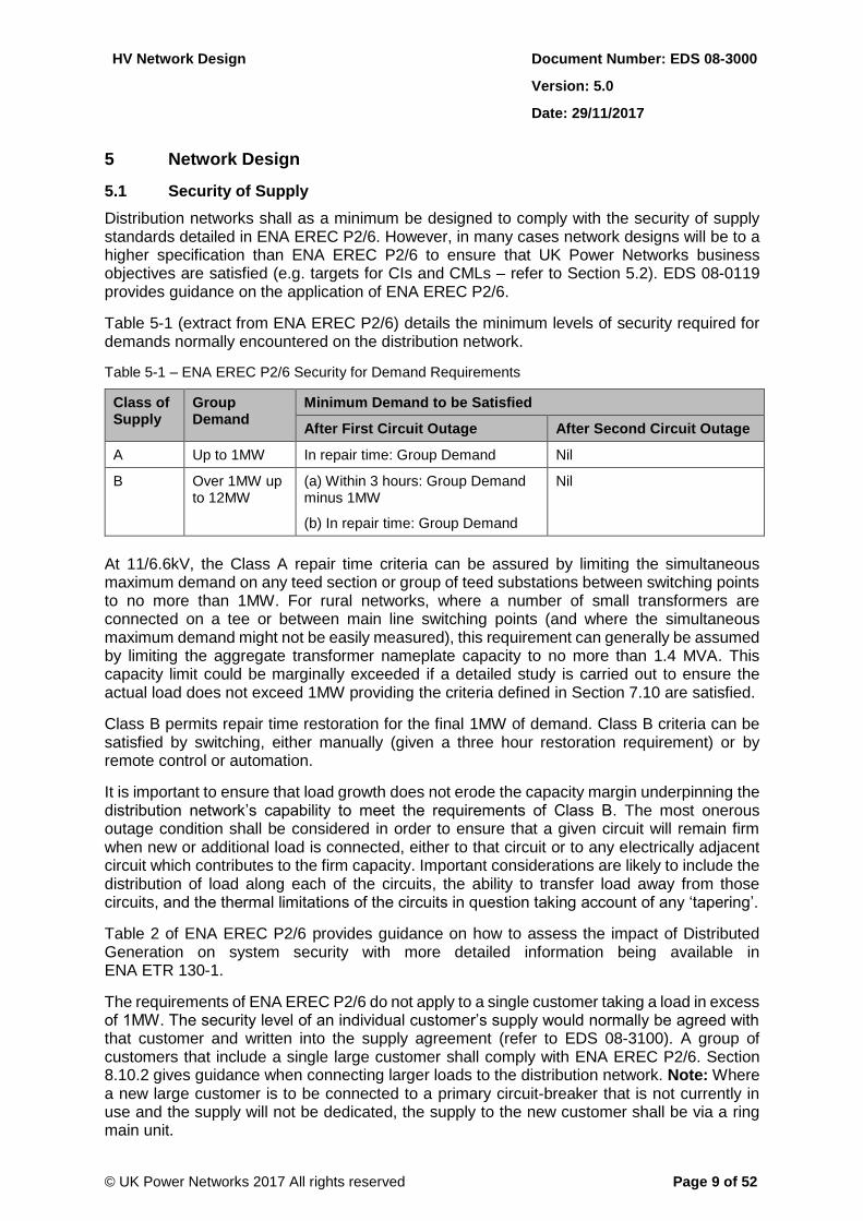
Table 5-1 (extract from ENA EREC P2/6) details the minimum levels of security required for demands normally encountered on the distribution network.
Table 5-1 – ENA EREC P2/6 Security for Demand Requirements
Class of Supply
Group Demand
Minimum Demand to be Satisfied
After First Circuit Outage After Second Circuit Outage
A Up to 1MW In repair time: Group Demand Nil
B Over 1MW up to 12MW
(a) Within 3 hours: Group Demand minus 1MW
(b) In repair time: Group Demand
Nil
At 11/6.6kV, the Class A repair time criteria can be assured by limiting the simultaneous maximum demand on any teed section or group of teed substations between switching points to no more than 1MW. For rural networks, where a number of small transformers are connected on a tee or between main line switching points (and where the simultaneous maximum demand might not be easily measured), this requirement can generally be assumed by limiting the aggregate transformer nameplate capacity to no more than 1.4 MVA. This capacity limit could be marginally exceeded if a detailed study is carried out to ensure the actual load does not exceed 1MW providing the criteria defined in Section 7.10 are satisfied.
Class B permits repair time restoration for the final 1MW of demand. Class B criteria can be satisfied by switching, either manually (given a three hour restoration requirement) or by remote control or automation.
It is important to ensure that load growth does not erode the capacity margin underpinning the distribution network’s capability to meet the requirements of Class B. The most onerous outage condition shall be considered in order to ensure that a given circuit will remain firm when new or additional load is connected, either to that circuit or to any electrically adjacent circuit which contributes to the firm capacity. Important considerations are likely to include the distribution of load along each of the circuits, the ability to transfer load away from those circuits, and the thermal limitations of the circuits in question taking account of any ‘tapering’.
Table 2 of ENA EREC P2/6 provides guidance on how to assess the impact of Distributed Generation on system security with more detailed information being available in ENA ETR 130-1.
The requirements of ENA EREC P2/6 do not apply to a single customer taking a load in excess of 1MW. The security level of an individual customer’s supply would normally be agreed with that customer and written into the supply agreement (refer to EDS 08-3100). A group of customers that include a single large customer shall comply with ENA EREC P2/6. Section 8.10.2 gives guidance when connecting larger loads to the distribution network. Note: Where a new large customer is to be connected to a primary circuit-breaker that is not currently in use and the supply will not be dedicated, the supply to the new customer shall be via a ring main unit.
HV Network Design Document Number: EDS 08-3000
Version: 5.0
Date: 29/11/2017
© UK Power Networks 2017 All rights reserved Page 10 of 52
A further consideration in the case of rural circuits is the effect of voltage regulation when the network is running abnormally due to an outage, this, rather than thermal capacity, might be the limiting factor in some cases.
5.2 Quality of Supply
The key performance measures used for measuring quality of supply are as follows:
Network security – measured in customer interruptions/100 connected customers (CI). This measure acts as a driver to reduce the occurrence of faults and to limit the impact of any one fault.
Network availability – measured in customer minutes lost/connected customer (CML). This measure acts as a driver to encourage fast restoration of un-faulted sections of network following a permanent fault.
The quality of supply performance targets agreed with OfGEM reflects the overall network performance and the following strategy is used to achieve these targets:
Improve the reliability of networks, thus reducing the number of faults.
Improve the network configuration to reduce the number of customers affected by a fault and improve the ability to re-supply customers.
Increase remote control and automation to reduce the time taken to restore supplies to un-faulted sections of the network.
Options for improving the performance of both underground cable and overhead line networks can be found in Section 10. These options should also be considered for schemes with drivers others than quality of supply (asset replacement, reinforcement etc.) with a view that any network development should not degrade the network performance, but aim to improve it.
5.3 Loads Causing Distortion of the Supply Voltage Waveform
Excessive distortion of the system voltage waveform, caused by certain types of load, may result in annoyance to users of the distribution system or damage to connected apparatus. National and international recommendations therefore apply regarding the maximum level of distortion which may be accepted on the distribution system. EDS 08-1901 defines standards based on ENA engineering recommendations with regard to connection of loads likely to cause disturbance.
5.4 Fault Levels
All electrical equipment connected to the network shall be able to withstand, without failure or damage, the maximum short-circuit conditions that it may be subjected to at the point where it is connected.
For underground networks the short circuit ratings of cables, both new and existing, shall also be considered. When networks are reinforced, fault levels increase and existing cables may need to be replaced or protection settings altered to avoid damage under fault conditions.
Additionally, for overhead line networks consideration has to be given to the short-circuit ratings to ensure that conductor failure or excessive sagging of conductors does not occur during fault conditions.
Refer to EDS 08-1110 for further information on fault levels.
HV Network Design Document Number: EDS 08-3000
Version: 5.0
Date: 29/11/2017
© UK Power Networks 2017 All rights reserved Page 11 of 52
5.5 Voltage Regulation
The low voltage limits shall be maintained within the declared range of 230 volts +10% and -6% both during normal running conditions and outage conditions. 11/6.6kV supplies are to be maintained at nominal voltage of +6% or -6%. Any reinforcement works used to maintain voltage conditions should also be aimed at providing improved network resilience.
Refer to EDS 05-0050 for further details on voltage regulation.
5.6 Voltage Rationalisation
5.6.1 6.6kV Networks
Where 6.6kV assets are to be replaced, 11kV rated plant, switchgear and cables shall be used. All new or replacement transformers used on the 6.6kV system should be dual ratio. Every endeavour should be made to remove 6.6kV rated assets as part of any major reinforcement scheme that either involves the assets directly, or offers the potential to decommission them as part of an associated scheme. Each case will ultimately be considered on its merits and the costs involved will be subject to formal approval as part of the capital authorisation procedure.
5.6.2 2kV/3.3kV and 3.5kV Networks
These networks shall not be extended. Where these assets are to be replaced the use of LV or 11kV rated switchgear and cables shall be used. Every endeavour should be made to remove 2-3.5kV rated assets as part of any reinforcement scheme that either involves the assets directly, or offers the potential to decommission them as part of an associated scheme. Each case will ultimately be considered on its merits and the costs involved will be subject to formal approval as part of the capital authorisation procedure.
5.7 System Earthing
5.7.1 Overview
Both solid (direct) and impedance (resistance and reactance) transformer neutral earthing can be found at grid and primary substations that supply the HV distribution networks. This is supplemented at some substations in EPN and SPN with an arc suppression coil.
5.7.2 Solidly Earthed Networks
Where the network is solidly earthed, the higher values of earth fault current need to be considered in the following situations:
Small section cables and overhead lines that are situated electrically close to the primary substation. Studies shall be carried out to ensure that earth fault ratings are sufficient to avoid damage during fault conditions.
Pole-mounted equipment where fault current may cause conductor or connection failure.
Earthed structures that may be subjected to a rise in potential during fault conditions, especially where 11/6.6kV and LV earths are separated.
HV Network Design Document Number: EDS 08-3000
Version: 5.0
Date: 29/11/2017
© UK Power Networks 2017 All rights reserved Page 12 of 52
5.7.3 Arc Suppression Coils
Extension of networks with underground cable may affect the tuning of or require the need to replace the arc suppression coil. Tuning of the arc suppression coil should always be checked following any alteration to the network. Refer to Section 7.5 for further information.
5.8 Remote Control and Automation
In order to maximise the opportunities arising from new connections and asset replacement the coverage of remote control on the secondary distribution network should be extended to improve the performance of the network, improve service to customers and help to meet the CI and CML targets set by OFGEM.
Automation is provided by template automation and the PowerOn Automatic Power Restoration System (APRS) which utilises all remotely controlled switches and circuit-breakers. APRS identifies faulty sections via fault passage indicators (FPI), isolates the faulty section and restores the healthy network within three minutes. APRS is targeted at achieving the OfGEM network security target (CIs) as well as providing a reduction in CMLs.
HV Network Design Document Number: EDS 08-3000
Version: 5.0
Date: 29/11/2017
© UK Power Networks 2017 All rights reserved Page 13 of 52
6 Urban/Suburban Network Design
6.1 Network Configuration
The principles detailed below should be applied when additions or alterations are made to the network. A simple network is a safe network. In designing any additions or alterations every endeavour should be made not to make the network more complicated.
6.2 Normal Method of Distribution
The normal method of 11/6.6 kV distribution is using open ring circuits feeding from the primary substation to normal open points that provide interconnection with adjacent circuits. Mesh type networks protected by unit protection and found in predominantly city areas are covered in Section 6.10.
6.3 Alternative Supplies
11/6.6kV underground cable networks should, where practical, be designed such that the primary method of alternative supply is via another 11/6.6kV circuit.
For a first fault outage, alternative supplies shall normally be restored to the healthy sections of the network by a single load transfer plus restoration from the source circuit-breaker (i.e. four switching operations). This may not be possible in established networks with small section cables. However no more than two load transfers plus restoration from the source circuit-breaker (i.e. six switching operations) are acceptable (refer to Appendix A.1).
Any network project should take into account these criteria and if they cannot be satisfied, this can be used to support the case for investment in network reconfiguration or reinforcement. However, nothing in this document shall be taken as tacit approval for investment and any proposed expenditure remains subject to the normal approval processes.
6.4 First Section of Circuit
The section of cable between the primary circuit-breaker and the first ring main unit shall be free of:
Teed transformer connections.
Teed connections that do not interconnect with another 11/6.6kV network.
Where practical no tees, including those interconnecting with another 11/6.6 kV network, shall be connected to the first section. This is to allow work or testing to be carried out on the primary switchgear without the need for disconnection of a teed site.
6.5 Circuit Mutual Support
Circuits from a primary substation that provide mutual support shall, where practicable, be connected to separate sections of the primary busbars, to provide security in the event of a busbar fault.
6.6 Interconnection across Circuits
Care should be taken to ensure that any interconnection across two circuits includes at least two ring main units of different types, refer to section 6.13. This ensures that only one circuit is affected by a ring main unit fault in a substation connected to the inter-connector as shown in Appendix A.2.
HV Network Design Document Number: EDS 08-3000
Version: 5.0
Date: 29/11/2017
© UK Power Networks 2017 All rights reserved Page 14 of 52
6.7 Network Complexity
To avoid the creation of complex networks the number of points of isolation to any switchboard should be limited to five (the local transformer switch fuse/circuit-breaker is to be included as a point of isolation) as shown in Appendix A.3.
6.8 Ring Connection of Networks
All new substations where either the substation or the site boundary is within 100 metres of an existing 11/6.6kV ring circuit to which the connection is to be made shall be ring connected. Where a new substation is within 100 metres of a ring circuit, but the nearest connection point is to an 11/6.6kV spur, this existing spur shall be reinforced to form part of the ring network.
All new substations which are situated further than 100 metres from an existing 11kV/6.6kV ring shall be ring connected where it is necessary:
To comply with ENA EREC P2/6.
To comply with the five isolation point rule in Section 6.7.
To avoid the connection of a ‘tee’ between the primary substation circuit-breaker and the first ring main unit on a circuit (refer to Section 6.4).
Where ‘ringing’ of a new substation is not necessary to comply with the above, this shall be referred to the Distribution Planning Manager. The Distribution Planning Manager will either agree the additional investment by UK Power Networks needed to enable the site to be ringed (or interconnected to another circuit) or agree the spur connected substation if costs of ringing are prohibitive. Account should be taken of the number of customers in terms of cost of CMLs weighed against additional cost for ringing. The additional expenditure by UK Power Networks will normally include any costs over and above those of a spur connection. Appendix C shows examples of where UK Power Networks would consider expenditure for the additional cost to ‘ring’ a new substation. The increase in system losses when ring connecting longer sections of network should also be taken into account.
The following criteria shall be used when measuring the distance from the existing ring circuit for the purposes of determining the need to ‘ring’ the new substation:
1. The measured underground cable route from the existing ring circuit shall be the optimal route.
2. Where the new substation is to provide supplies to more than one customer and will be positioned further from the existing ring circuit than the optimum electrical position for the development site, the measured distance shall be from the closest boundary of the development site.
3. Where the new substation is to provide a supply to an individual customer, the measured distance shall be from the existing ring circuit to the nearest boundary of the customer’s property.
Note: In the case of a staged development, where the new substation may temporarily be spur connected but will then be ringed on completion of the development, refer to Section 8.8.
HV Network Design Document Number: EDS 08-3000
Version: 5.0
Date: 29/11/2017
© UK Power Networks 2017 All rights reserved Page 15 of 52
6.9 Second Stage ‘Network’ Protection
Remote control second stage protection was used on the EPN and SPN network before the introduction of large scale automation to provide automatic sectionalisation during a fault. The second stage protection was generally provided by either an individual network circuit-breaker (e.g. Schneider CE6) or via a ring main circuit-breaker (e.g. RN6c). Many of the individual circuit-breakers were installed alongside older oil switchgear.
Any network reconfiguration or switchgear replacement should consider whether second stage protection is still required as it is likely that automation will make many second stage protection sites redundant. If second stage protection is required the following shall be considered:
Integration with other switchgear on site.
Protection grading with other upstream and downstream devices.
6.10 Mesh Circuits
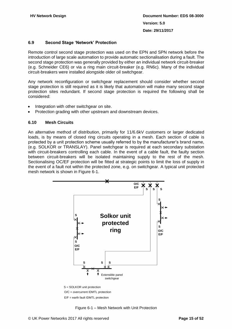
An alternative method of distribution, primarily for 11/6.6kV customers or larger dedicated loads, is by means of closed ring circuits operating in a mesh. Each section of cable is protected by a unit protection scheme usually referred to by the manufacturer’s brand name, (e.g. SOLKOR or TRANSLAY). Panel switchgear is required at each secondary substation with circuit-breakers controlling each cable. In the event of a cable fault, the faulty section between circuit-breakers will be isolated maintaining supply to the rest of the mesh. Sectionalising OC/EF protection will be fitted at strategic points to limit the loss of supply in the event of a fault not within the protected zone, e.g. on switchgear. A typical unit protected mesh network is shown in Figure 6-1.
O/C
E/F
S SS
S
S
S
S
S S S
O/C
E/F
O/C
E/F
Solkor unit
protected
ring
S = SOLKOR unit protection
O/C = overcurrent IDMTL protection
E/F = earth fault IDMTL protection
Extensible panel
switchgear
Figure 6-1 – Mesh Network with Unit Protection
HV Network Design Document Number: EDS 08-3000
Version: 5.0
Date: 29/11/2017
© UK Power Networks 2017 All rights reserved Page 16 of 52
6.11 Central London Special Requirements
6.11.1 Interconnection of LV and 11kV Networks
Within the LPN network, there are a variety of system types associated with 11/6.6kV and LV networks. Areas of Central London continue to be supplied by interconnected LV networks with the associated 11/6.6kV feeders operating in discrete groups. This concept started with the adoption of the Leach (Leach – Standardisation of Distribution on Densely Loaded Areas – IEE Journal 1941) standard network which utilised a meshed solidly interconnected LV cable system and set the design philosophy for the whole of the London Electricity area over the 1950s to 1970s. In the 1980s safety concerns dictated the removal of the solid LV interconnection, which led to fused interconnection in the central area, while outlying areas were converted to radial LV operation.
The design constrains the network (either 6.6kV or 11kV) as a feeder group associated with a discrete area of LV network which is dictated by the interaction between the 11/6.6kV and LV levels under fault conditions. In effect, the 11/6.6kV and LV levels are integrated and this precludes straightforward alterations to either without affecting the integrity of the whole.
The interconnection at LV provides the potential for maintaining supply when an 11/6.6kV feeder is lost, by back-feeding the affected distribution substations through the LV network. This is not a guaranteed arrangement, as system loading and temporary changes to the network can degrade the performance, but it does afford additional security in favourable circumstances. The design and operation of the interconnected LV network is a complex subject that is outside the scope of this brief overview and the documents referred to in 6.11.2 and 6.11.3 provide more detailed information.
6.11.2 System 4 Networks
The latest recognised design for an interconnected system consists of an interleaved 11/6.6kV network with fused LV interconnection and is referred to as System 4. This forms the current basis for fused LV interconnected networks but a full System 4 design may require extensive alterations to the 11/6.6kV network to achieve the required interleaving. For further information refer to EDS 08-0140.
6.11.3 System 8 Networks
Where existing interconnected networks fail to perform adequately under fault conditions, the network will be assessed with a view to converting it to what has been called the System 8 design. This utilises simple LV interconnection between adjacent secondary substations on the same circuit to address high load density and short term support, and then a two-stage automation scheme to restore supplies in the event of an 11/6.6 kV fault. For further information refer to EDS 08-0111.
HV Network Design Document Number: EDS 08-3000
Version: 5.0
Date: 29/11/2017
© UK Power Networks 2017 All rights reserved Page 17 of 52
6.12 Remote Control and Monitoring
Remote control of distribution switchgear allows the network to be quickly reconfigured following a fault. The time for restoration by remote control (via the Control Engineer) will normally be more than 3 minutes. The benefit of remote control is therefore targeted at achieving the OfGEM network availability target (CML). The following shall be considered when designing remote control installations:
Remote control of the source circuit-breaker is available.
Source protection settings are reviewed to ensure there is grading along the circuit and that there is no risk of trip following a load transfer.
Network studies are carried out to ensure that any load transferred to an adjacent circuit following a fault will not cause thermal overloading of any part of the circuit.
Statutory voltage limits are maintained following a load transfer especially where generation is concerned.
Load transfers carried out under the direction of the control engineer may be made to more than one circuit.
Positions of any priority customers, such as hospitals, are identified.
Where practicable the network being reviewed should be simplified to take full advantage of the use of ring main equipment, reducing the number of multi-panel boards as set out in Sections 6.1 and 9.
The addition of new switchgear or the replacement of existing switchgear adjacent to an existing non-remotely controlled normal open point (NOP) should replace the existing open point as a remotely controlled NOP. If in doing this, more than 1MVA of load is to be moved between circuits, Distribution Planning shall be consulted before any such alteration is completed.
Remote control and monitoring shall be applied in accordance with EBB 03-0102 and EDS 08-3001.
Remote control is not required on 2-3.5kV networks. All other exceptions shall be agreed with Distribution Planning Manager.
HV Network Design Document Number: EDS 08-3000
Version: 5.0
Date: 29/11/2017
© UK Power Networks 2017 All rights reserved Page 18 of 52
6.13 Plant and Equipment
6.13.1 Switchgear
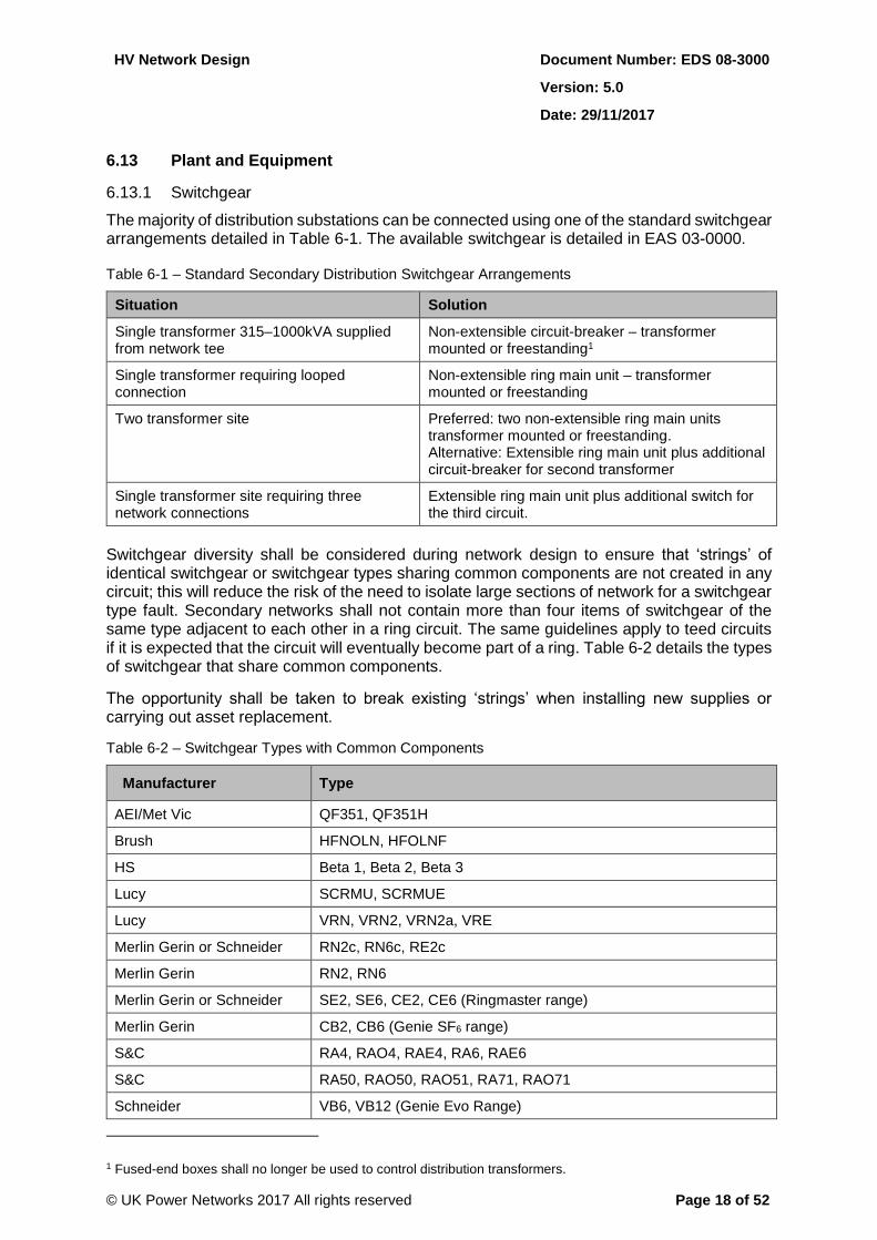
The majority of distribution substations can be connected using one of the standard switchgear arrangements detailed in Table 6-1. The available switchgear is detailed in EAS 03-0000.
Table 6-1 – Standard Secondary Distribution Switchgear Arrangements
Situation Solution
Single transformer 315–1000kVA supplied from network tee
Non-extensible circuit-breaker – transformer mounted or freestanding1
Single transformer requiring looped connection
Non-extensible ring main unit – transformer mounted or freestanding
Two transformer site Preferred: two non-extensible ring main units transformer mounted or freestanding. Alternative: Extensible ring main unit plus additional circuit-breaker for second transformer
Single transformer site requiring three network connections
Extensible ring main unit plus additional switch for the third circuit.
Switchgear diversity shall be considered during network design to ensure that ‘strings’ of identical switchgear or switchgear types sharing common components are not created in any circuit; this will reduce the risk of the need to isolate large sections of network for a switchgear type fault. Secondary networks shall not contain more than four items of switchgear of the same type adjacent to each other in a ring circuit. The same guidelines apply to teed circuits if it is expected that the circuit will eventually become part of a ring. Table 6-2 details the types of switchgear that share common components.
The opportunity shall be taken to break existing ‘strings’ when installing new supplies or carrying out asset replacement.
Table 6-2 – Switchgear Types with Common Components
Manufacturer Type
AEI/Met Vic QF351, QF351H
Brush HFNOLN, HFOLNF
HS Beta 1, Beta 2, Beta 3
Lucy SCRMU, SCRMUE
Lucy VRN, VRN2, VRN2a, VRE
Merlin Gerin or Schneider RN2c, RN6c, RE2c
Merlin Gerin RN2, RN6
Merlin Gerin or Schneider SE2, SE6, CE2, CE6 (Ringmaster range)
Merlin Gerin CB2, CB6 (Genie SF6 range)
S&C RA4, RAO4, RAE4, RA6, RAE6
S&C RA50, RAO50, RAO51, RA71, RAO71
Schneider VB6, VB12 (Genie Evo Range)
1 Fused-end boxes shall no longer be used to control distribution transformers.
HV Network Design Document Number: EDS 08-3000
Version: 5.0
Date: 29/11/2017
© UK Power Networks 2017 All rights reserved Page 19 of 52
6.13.2 Transformers
Transformers shall ideally be of the unit type, directly coupled to the ring main unit. The standard sizes of distribution transformer for underground networks are 315/500/800/1000kVA (refer to EAS 04-0000). In town centres and shopping areas, a 500kVA transformer should normally be the minimum capacity installed (other than at a single user site where the installed transformer capacity should be matched to the demand required). EDS 08-0115 details the criteria for determining the rating of a new distribution transformer. Where circumstances dictate a pad-mount transformer can be used in accordance with EOS 04-0035.
Freestanding pole-mounted transformers shall not be used in new or the extension of existing networks. Where overhead line networks are diverted and would create a freestanding transformer it shall be replaced with a ground-mounted substation. However it is acceptable to upgrade an existing freestanding pole-mounted transformer to a maximum of 100kVA providing this complies with the relevant customer connection standard.
6.13.3 Pad-mount Transformers
Pad-mount transformers (that do not have 11/6.6kV isolation) shall not be connected on a permanent basis to urban 11/6.6kV networks. Where practicable it is preferable to connect to an established underground LV network or to install a ground-mounted substation having 11/6.6kV transformer isolation, however they may be used in the following situations.
Temporary supplies for construction works.
Interim supplies during the development of a site, prior to the installation of permanent network (subject to the approval of the Distribution Planning Manager).
Site supplies where 11/6.6kV isolation is provided (e.g. ring main unit).
The available equipment is detailed in EAS 04-0000.
6.13.4 LV Cabinets, Boards and Pillars
The available equipment is detailed in EAS 13-0000.
6.13.5 Cables
EDS 02-0027 details the technical information required to use 11kV triplex cable and provides rating comparisons with other cable designs.
6.13.6 Ducting of Cables and Spare Ducts
Cables installed in the following locations shall be laid in a duct:
Road crossings.
Across bridges.
Rail crossings.
Paved pedestrian areas.
Town centre locations where future excavation may be difficult because of traffic management issues.
Any other location where future excavation will be difficult and/or expensive.
It should however be noted that when a cable is installed in a duct, the reduction in its rating may require the additional cost of a larger size cable.
HV Network Design Document Number: EDS 08-3000
Version: 5.0
Date: 29/11/2017
© UK Power Networks 2017 All rights reserved Page 20 of 52
Spare ducts shall also be provided in the above situations to accommodate future cables. However where this requires additional expenditure by UK Power Networks, approval from the Distribution Planning Manager shall be obtained.
Generally underground cables in footpaths and unmade land should be laid directly in the ground.
6.13.7 Fault Passage Indicators
As a minimum all new or replacement ring main units shall include a fault passage indicator on the normally outgoing switch.
All switches with remote control shall have a fault passage indicator as detailed in Section 6.12.
EOS 05-6003 contains further information on the application of fault passage indicators.
6.14 Substation Sites
The standard for secondary distribution substation site acquisition and design is detailed in EDS 07-3101. This document defines the process for establishing an additional substation in a new development.
HV Network Design Document Number: EDS 08-3000
Version: 5.0
Date: 29/11/2017
© UK Power Networks 2017 All rights reserved Page 21 of 52
7 Rural Network Design
7.1 Network Configuration
As the 11/6.6kV overhead line network is already established, the design parameters detailed in this section are to be considered as targets for network configuration that should be incorporated into reinforcement, asset replacement and new business projects.
Circuits are to be designed as three-phase open rings with interconnection from adjacent circuits. Three-phase distribution transformers supplying three-phase low voltage networks, is the normal method of distribution. In many areas single-phase 2-wire spurs are teed from the three-phase network to provide supply to small communities or individual customers via single-phase transformers. In these situations transformers are connected for 2-wire (230V) or 3-wire (230/460V) low voltage working. However single-phase networks may cause voltage unbalance in the 11/6.6 kV network and ENA EREC P29 details the planning limits for voltage unbalance in the UK. The limits specified relate to voltage unbalance attributed to new load. The level of voltage unbalance is to be kept to a minimum to reduce losses and maintain voltage limits. Network extensions and reinforcement (including reconductoring) shall use three-phase and Section 7.5 defines the restrictions required when overhead lines are replaced or extended with underground cables.
Appendix F illustrates various rural network configurations.
7.2 Network Security and Complexity
The standards of security of supply for rural networks shall be the same as for urban networks and are detailed in Section 5.1. Particular attention should be given to the ability to provide support to primary substations having a single 33/11kV or 6.6kV transformer.
To avoid the creation of complex networks the number of points of isolation to any switchboard should be limited to seven (the local transformer switch fuse/circuit-breaker is to be included as a point of isolation).
7.3 Circuit Length
The target length for a rural circuit should be approximately 24km of connected circuit. However in low-density population areas it is accepted that longer circuits may be required.
7.4 Current Ratings of Overhead Lines
Current ratings for 11/6.6kV overhead lines are sustained ratings based on a maximum conductor operating temperature of 50°C, with values for spring/autumn, winter and summer operation. EDS 01-0045 and ENA EREC P27 set out the values to be used for SPN and EPN networks.
HV Network Design Document Number: EDS 08-3000
Version: 5.0
Date: 29/11/2017
© UK Power Networks 2017 All rights reserved Page 22 of 52
7.5 Restrictions for the Replacement, Diversion or Extension of HV Overhead Lines
7.5.1 Overview
The addition of excessive lengths of underground cable or screened aerial cables into HV overhead networks can cause the undesirable effects detailed below unless the appropriate mitigation is applied.
Ferro-resonance (refer to Appendix H).
Voltage unbalance (refer to Appendix H).
Neutral voltage displacement (refer to Appendix H).
Need for ASC reinforcement.
Voltage increase.
Harmonic voltage distortion increase.
This section details the restrictions that shall be applied during the replacement, diversion or extension of HV overhead lines by underground cable. All alterations and extensions to HV distribution networks shall be planned and constructed in accordance with these restrictions.
Note: Where these restrictions have already been exceeded then risks should be controlled by operational measures until such time that they can be resolved.
7.5.2 Ferro-resonance
The length of underground cable beyond any un-ganged devices (e.g. switchgear, fuses, ASLs etc.) or live-line-taps shall be limited to 250 metres to reduce the likelihood of ferro-resonance. Where underground cable is added that would cause this limit to be exceeded the un-ganged device or live-line-taps shall be replaced with permanent connections, ABSD or a pole-mounted switch/recloser.
7.5.3 Voltage Unbalance
Generally single-phase spurs should not be extended. However, if the extension is unavoidable, converting the single-phase spur to three-phase is the preferred option and only as a last resort, should the spur be extended using single-phase cable.
The maximum length of underground cable that may be connected to a single-phase spur is 100 metres. If the length is above 100 metres, an assessment shall be performed by Distribution Planning to calculate the voltage unbalance.
7.5.4 Additional Restrictions for ASC Earthed Systems
The following restrictions shall be considered when designing any replacement, diversion or extension of an HV overhead network using underground cable on networks with an ASC:
1. If the ASC hasn’t been inspected in the last 2 years, an inspection shall be carried out, regardless of the length of underground cable being connected in a single project, to determine the amount of spare capacity. Refer to EDS 08-0147.
2. The maximum length of underground cable that may be connected to a single-phase spur is 100 metres.
HV Network Design Document Number: EDS 08-3000
Version: 5.0
Date: 29/11/2017
© UK Power Networks 2017 All rights reserved Page 23 of 52
3. If cable has to be removed, an assessment of the overall network out-of-balance has to be performed.
4. The maximum length of three-phase underground cable that may be connected in a single project without considering the need for additional ASC capacity is 1000 metres. Where a proposal exceeds this limit the spare charging current capacity on the ASC shall be established to determine if the extension can be accommodated. Typically an ASC capacity in the order of 2A is required for each 1000 metres of three-phase underground cable added. Refer to EDS 08-0147.
If (2), (3) or (4) above is being considered then retuning or the augmentation of the capacity of the ASC shall also be considered.
7.6 Connection of Overhead and Underground Spurs to Overhead Lines
7.6.1 Overhead Spurs
Overhead line spurs in excess of 1km (10 spans) should be protected by automatic sectionalising links (ASLs) if downstream of a multi-shot auto-recloser (Section 7.9).
If the spur is controlled by a source circuit-breaker that does not have multi-shot auto-reclose protection expulsion fuses should be used. Network studies should however first be carried out to confirm that the fault level at any location where expulsion fuses are to be installed is less than 8.0kA (150MVA for 11kV networks).
ASLs and expulsion fuses shall not be used on spurs connected to a generation site.
7.6.2 Connection of Underground Cables
Underground cables of less than 100 metres in length can be connected solidly to the overhead line. Spurs with between 100 and 250 metres of underground cable should be protected by ASLs or fuses as detailed in Section 7.6.1.
Underground spurs greater than 250 metres in length should:
Be protected by ganged ASLs (except for spurs connected to a generation site) if the upstream auto recloser is multi-shot.
Be connected solid if the network is not protected by a multi-shot auto recloser, with fault passage indicators on the main line, one span upstream and downstream from the tee pole.
Have an ABSD where practicable to provide an isolation point for the underground spur.
Have, on the rare occasions where the network requires, a pole mounted auto-recloser to control the spur (Section 7.9).
All underground cable spurs shall comply with Section 7.5.
7.7 Connection of Ground Mounted Transformers to Overhead Line Networks
All new ground-mounted transformers should be protected with either expulsion fuses or a circuit-breaker but not by a fused end box (FEB). The required fuse ratings are defined in EDS 05-4001.
HV Network Design Document Number: EDS 08-3000
Version: 5.0
Date: 29/11/2017
© UK Power Networks 2017 All rights reserved Page 24 of 52
7.8 Connection of Single-phase Pad-mounted Substations to Overhead Line Networks
Section 7.5 defines the maximum acceptable length of underground cable connected to a single-phase pad-mount substation. The connection arrangement for the underground cable from the pole termination to the transformer is detailed in EOS 04-0035.
7.9 Pole-mounted Recloser and Switches
A remotely controlled pole-mounted recloser or switch shall be installed at points on the overhead line network to ensure the maximum number of customers between remote control points is 350 or less.
Reclosers reduce CIs through the management of transient faults and automatic isolation of permanent downstream faults and are therefore preferred. Where protection grading allows two reclosers may be installed in series. Note: The type of auto-reclose scheme installed on the source circuit-breaker and the protection grading with the source circuit-breaker and other reclosers will affect the positioning of any recloser. Refer to the protection settings manual for recloser settings.
Additionally a remotely controlled pole-mounted switch shall be installed at all normal open points on overhead line circuits.
The optimum location for devices is to be determined through network analysis using the approved network modelling tool. Network studies are required to determine the capability of the network to support load transfers resulting from the operation of remote control or an automation scheme.
All remotely controlled reclosers or switches shall be located to provide suitable access for installation, operation and maintenance.
7.10 Air Break Switch Disconnectors
The application of pole-mounted reclosers and switches as detailed in Section 7.9 should be considered before using air break switch disconnectors (ABSDs).
7.10.1 Air Break Switch Disconnectors – Main Lines
The total length of line between ABSDs including main line and any spurs or part spurs connected to that section of main line should not exceed 3km. The spacing between ABSDs should however also reflect the number of customers connected in the section of line and as a guide, the spacing between ABSDs should conform to the following formula:
Number of customers solidly connected to main line x length of line (km) ≤ than 300
This is illustrated in Appendix G.
There will be many cases where the value is less than this, in which case intermediate ABSDs may be removed provided the product of line length and customers is approximately 300 for the enlarged zone. The lengths of overhead line can be estimated on the basis of an average span length of 100 metres and in most cases, the number of customers per substation is available from PowerOn. If customer numbers are not available by other means, these can be estimated from the transformer capacity (4.0kVA of capacity/customer for rural locations and 2.5 kVA/customer in more densely populated areas).
HV Network Design Document Number: EDS 08-3000
Version: 5.0
Date: 29/11/2017
© UK Power Networks 2017 All rights reserved Page 25 of 52
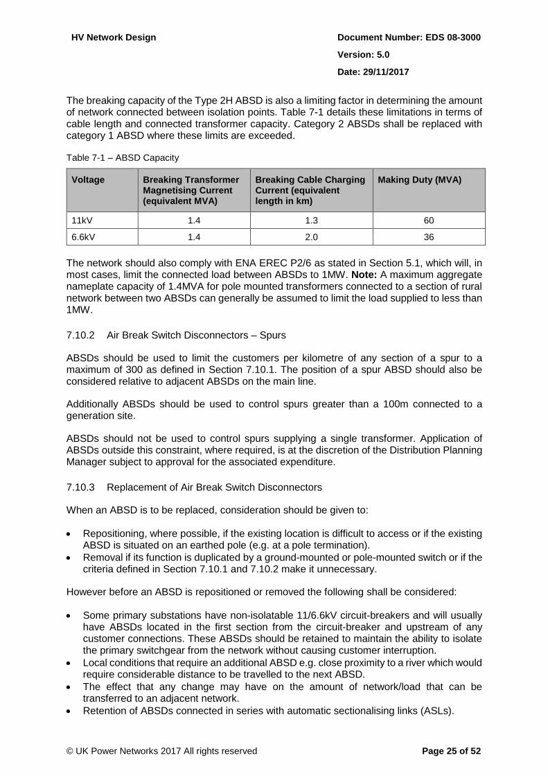
The breaking capacity of the Type 2H ABSD is also a limiting factor in determining the amount of network connected between isolation points. Table 7-1 details these limitations in terms of cable length and connected transformer capacity. Category 2 ABSDs shall be replaced with category 1 ABSD where these limits are exceeded.
Table 7-1 – ABSD Capacity
Voltage Breaking Transformer Magnetising Current (equivalent MVA)
Breaking Cable Charging Current (equivalent length in km)
Making Duty (MVA)
11kV 1.4 1.3 60
6.6kV 1.4 2.0 36
The network should also comply with ENA EREC P2/6 as stated in Section 5.1, which will, in most cases, limit the connected load between ABSDs to 1MW. Note: A maximum aggregate nameplate capacity of 1.4MVA for pole mounted transformers connected to a section of rural network between two ABSDs can generally be assumed to limit the load supplied to less than 1MW.
7.10.2 Air Break Switch Disconnectors – Spurs
ABSDs should be used to limit the customers per kilometre of any section of a spur to a maximum of 300 as defined in Section 7.10.1. The position of a spur ABSD should also be considered relative to adjacent ABSDs on the main line.
Additionally ABSDs should be used to control spurs greater than a 100m connected to a generation site.
ABSDs should not be used to control spurs supplying a single transformer. Application of ABSDs outside this constraint, where required, is at the discretion of the Distribution Planning Manager subject to approval for the associated expenditure.
7.10.3 Replacement of Air Break Switch Disconnectors
When an ABSD is to be replaced, consideration should be given to:
Repositioning, where possible, if the existing location is difficult to access or if the existing ABSD is situated on an earthed pole (e.g. at a pole termination).
Removal if its function is duplicated by a ground-mounted or pole-mounted switch or if the criteria defined in Section 7.10.1 and 7.10.2 make it unnecessary.
However before an ABSD is repositioned or removed the following shall be considered:
Some primary substations have non-isolatable 11/6.6kV circuit-breakers and will usually have ABSDs located in the first section from the circuit-breaker and upstream of any customer connections. These ABSDs should be retained to maintain the ability to isolate the primary switchgear from the network without causing customer interruption.
Local conditions that require an additional ABSD e.g. close proximity to a river which would require considerable distance to be travelled to the next ABSD.
The effect that any change may have on the amount of network/load that can be transferred to an adjacent network.
Retention of ABSDs connected in series with automatic sectionalising links (ASLs).
HV Network Design Document Number: EDS 08-3000
Version: 5.0
Date: 29/11/2017
© UK Power Networks 2017 All rights reserved Page 26 of 52
7.11 Automatic Sectionalising Links
7.11.1 Overview
ASLs are used to reduce the number of CIs and can be installed on overhead line or underground spurs which are downstream of source circuit-breakers with multi-shot2 auto-reclose or pole-mounted auto-reclosers.
ASLs should be used to:
1. Protect overhead line spurs with more than 1km (10 spans) of overhead line providing the total transformer capacity does not exceed the values shown in Table 7-2. ASLs can be used to replace existing expulsion fuses on overhead line spurs and can be installed into the fuse holders without alteration.
2. Protect underground cable fed transformers supplied from overhead line providing:
The total connected transformer capacity does not exceed the values in Table 7-2.
Each ground-mounted transformer has its own upstream protection.
The circuit complies with the restrictions detailed in Section 7.5 and ganged ASLs are used to control three-phase spurs to prevent ferro-resonance and damage to customer’s equipment during a single-phase fault (refer to Section 7.5).
ASLs shall not be used on a spur connected to a generation site.
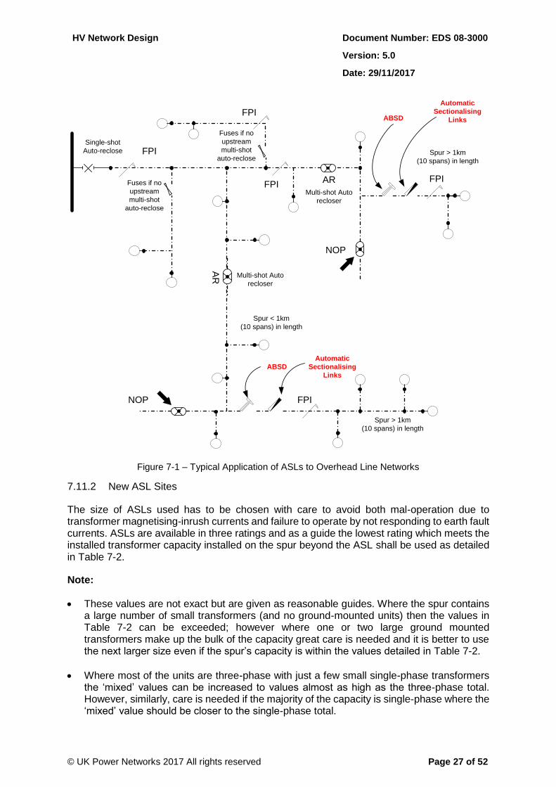
Figure 7-1 shows the use of ASLs within a typical overhead line network.
ASLs shall be selected in accordance with Section 7.11.2and 7.11.3 and may require additional isolation in accordance with Section 7.11.4.
2 ASLs will not function where the circuit-breaker controlling the circuit is set for repetitive single-shot operation only.
HV Network Design Document Number: EDS 08-3000
Version: 5.0
Date: 29/11/2017
© UK Power Networks 2017 All rights reserved Page 27 of 52
Spur < 1km
(10 spans) in length
Spur > 1km
(10 spans) in length
NOP
Single-shot
Auto-reclose
AR
FPI
Fuses if no
upstream
multi-shot
auto-reclose
Spur > 1km
(10 spans) in length
NOP
Multi-shot Auto
recloser
Automatic
Sectionalising
Links
Automatic
Sectionalising
Links
Multi-shot Auto
recloser
AR
Fuses if no
upstream
multi-shot
auto-reclose
FPI
FPIFPI
FPI
ABSD
ABSD
Figure 7-1 – Typical Application of ASLs to Overhead Line Networks
7.11.2 New ASL Sites
The size of ASLs used has to be chosen with care to avoid both mal-operation due to transformer magnetising-inrush currents and failure to operate by not responding to earth fault currents. ASLs are available in three ratings and as a guide the lowest rating which meets the installed transformer capacity installed on the spur beyond the ASL shall be used as detailed in Table 7-2.
Note:
These values are not exact but are given as reasonable guides. Where the spur contains a large number of small transformers (and no ground-mounted units) then the values in Table 7-2 can be exceeded; however where one or two large ground mounted transformers make up the bulk of the capacity great care is needed and it is better to use the next larger size even if the spur’s capacity is within the values detailed in Table 7-2.
Where most of the units are three-phase with just a few small single-phase transformers the ‘mixed’ values can be increased to values almost as high as the three-phase total. However, similarly, care is needed if the majority of the capacity is single-phase where the ‘mixed’ value should be closer to the single-phase total.
HV Network Design Document Number: EDS 08-3000
Version: 5.0
Date: 29/11/2017
© UK Power Networks 2017 All rights reserved Page 28 of 52
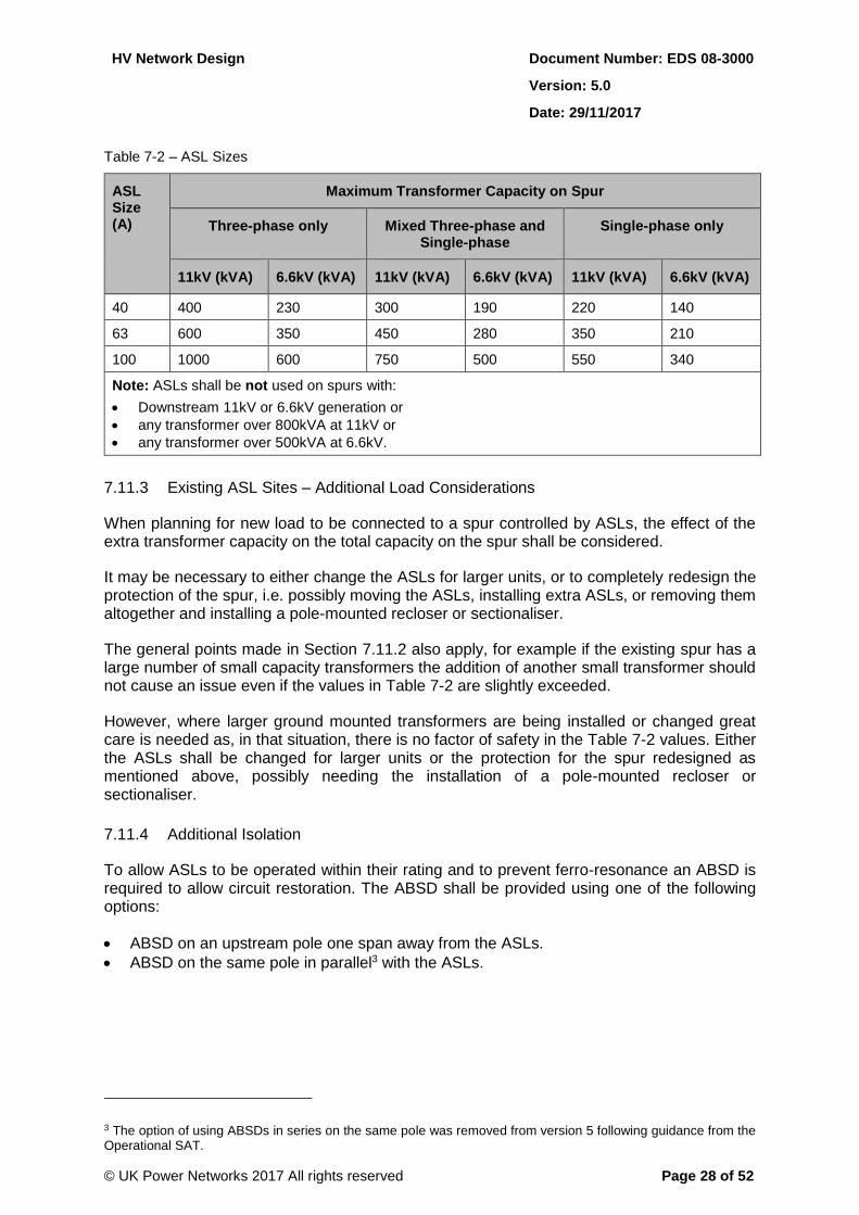
Table 7-2 – ASL Sizes
ASL Size (A)
Maximum Transformer Capacity on Spur
Three-phase only Mixed Three-phase and Single-phase
Single-phase only
11kV (kVA) 6.6kV (kVA) 11kV (kVA) 6.6kV (kVA) 11kV (kVA) 6.6kV (kVA)
40 400 230 300 190 220 140
63 600 350 450 280 350 210
100 1000 600 750 500 550 340
Note: ASLs shall be not used on spurs with:
Downstream 11kV or 6.6kV generation or
any transformer over 800kVA at 11kV or
any transformer over 500kVA at 6.6kV.
7.11.3 Existing ASL Sites – Additional Load Considerations
When planning for new load to be connected to a spur controlled by ASLs, the effect of the extra transformer capacity on the total capacity on the spur shall be considered.
It may be necessary to either change the ASLs for larger units, or to completely redesign the protection of the spur, i.e. possibly moving the ASLs, installing extra ASLs, or removing them altogether and installing a pole-mounted recloser or sectionaliser.
The general points made in Section 7.11.2 also apply, for example if the existing spur has a large number of small capacity transformers the addition of another small transformer should not cause an issue even if the values in Table 7-2 are slightly exceeded.
However, where larger ground mounted transformers are being installed or changed great care is needed as, in that situation, there is no factor of safety in the Table 7-2 values. Either the ASLs shall be changed for larger units or the protection for the spur redesigned as mentioned above, possibly needing the installation of a pole-mounted recloser or sectionaliser.
7.11.4 Additional Isolation
To allow ASLs to be operated within their rating and to prevent ferro-resonance an ABSD is required to allow circuit restoration. The ABSD shall be provided using one of the following options:
ABSD on an upstream pole one span away from the ASLs.
ABSD on the same pole in parallel3 with the ASLs.
3 The option of using ABSDs in series on the same pole was removed from version 5 following guidance from the Operational SAT.
HV Network Design Document Number: EDS 08-3000
Version: 5.0
Date: 29/11/2017
© UK Power Networks 2017 All rights reserved Page 29 of 52
7.12 Remote Control
Pole-mounted circuit-breakers and switches at normal open points shall be used to provide remote control of overhead line circuits. The optimum location for devices is to be determined through network analysis using the approved network modelling tool. Network studies are required to determine the capability of the network to support load transfers resulting from the operation of the remote control or an automation scheme.
7.13 Fault Passage Indicators
Pole-mounted fault passage indicators (FPI) shall be installed as follows:
On the first pole downstream of normally closed ABSDs (or upstream if the downstream pole is unsuitable).
On the first pole downstream of the ASLs.
One span upstream or downstream of a tee pole where a spur has been connected which is not controlled by ASLs (Section 7.6.2 above).
At any strategic location along the circuit that will improve the speed of fault location e.g. where the circuit splits or where the circuit crosses a geographic feature such as a river.
Care shall be taken in the siting of pole-mounted indicators, so that they do not mal-operate in response to other currents unrelated to the circuit which they are intended to monitor. In general, they should not be mounted on angle or section poles, or poles which carry tee-off lines, underground cables, earthing conductors, or other equipment (transformers, air-break switches, auto-reclosers etc) and should not be close to other HV circuits. The specific manufacturer’s installation advice should be observed in each case.
Refer to EOS 05-6003 for further information.
7.14 Compact Covered Conductor
Compact covered (CC) conductor to ENA TS 43-121 may be used for the following:
As a solution to a safety issue where a risk to the public has been identified. In these situations a risk assessment is required as detailed in EOS 09-0061. The proposed solution is required to reduce the risk to a low or medium risk rating.
To improve the performance at specific sites. CC conductor reduces the likelihood of faults caused by windborne material, birds, etc. and therefore it can be installed in parts of the network that are affected by these types of fault.
The reconstruction of open wire networks to ENA TS 43-40 may not produce the levels of performance required. The use of CC conductor, which is attributed with a lower fault rate, can provide a method of attaining the required level of performance for a circuit. However the use of CC is deemed not suitable where the overhead line location is across open areas which may be subject to a high risk of a lightning strike, as this may pose a detrimental performance risk to the circuit.
Note: The standard fittings used for CC conductor systems are susceptible to airborne salt corrosion. Any CC conductor installations that are sited within 8km of the sea are to be constructed to the CC conductor ‘coastal specification’.
Refer to the Overhead Lines Construction manual for further information.
HV Network Design Document Number: EDS 08-3000
Version: 5.0
Date: 29/11/2017
© UK Power Networks 2017 All rights reserved Page 30 of 52
7.15 Underground Networks
7.15.1 General
While the undergrounding of overhead line networks has the potential to improve the reliability of the supply, replacing one or two spans with underground cable is likely to make fault location more difficult and the earthing of newly installed ground-mounted substations more onerous. Therefore continuous overhead networks are preferred to piecemeal overhead/underground networks.
7.15.2 Distributed Rural Loads and Areas of Outstanding Natural Beauty (AONB) Schemes
These networks should be designed on a ring main – tee – ring main basis where practical. An additional tee may be acceptable if it is to a single infrequent usage load (e.g. an irrigation unit or grain drier). Where practicable, provision shall also be made for the safe parking and operation of a generator either in or adjacent to the teed substation sites, taking into account the impact of noise and exhaust emissions. If these criteria cannot be satisfied, a ring-connected substation is required. When any isolated tee cable is to be installed, the provision of a spare duct for future reinforcement shall be considered. This shall be referred to the Distribution Planning Manager who will agree the additional investment needed if the duct is considered of benefit to the future development of the network.
7.15.3 Villages
There are many villages where the 11/6.6kV network has been developed in a piecemeal manner resulting in numerous tees from an adjacent overhead line and tee on tee connections have been allowed to develop. The increasing need to improve network performance requires this type of network to be reviewed. Rural underground cable networks are to be developed on the same basis applied to urban networks. Underground sections of any rural/mixed network are to be reviewed as part of the network analysis for quality of supply improvement. Any proposals for new developments or network reinforcement shall take into account where practicable the need to simplify networks and improve network performance.
HV Network Design Document Number: EDS 08-3000
Version: 5.0
Date: 29/11/2017
© UK Power Networks 2017 All rights reserved Page 31 of 52
8 New Connections
8.1 Overview
CON 05 109 details the process for dealing with all requests for all new load and alterations to the network. In addition to providing a supply to meet customers’ requirements, the design shall satisfy all current design standards. Designs shall comply with ENA EREC P2/6 as a minimum (refer to Section 5.1) and the network configuration shall be reviewed to ensure the continuing integrity of automation scheme normal open points and automatic switching points.
8.2 Network Complexity
The operational standards set out in Section 6.1 are to be maintained and any network alterations should not increase network complexity.
8.3 Town Centre Networks
In town centres and shopping areas, distribution substations shall be ring connected i.e. by the installation of ring main unit switchgear within the radial network. Transformers that supply the LV distribution network shall normally have a minimum rating of 500kVA as defined in Section 6.13.2. Where, as a result of this, additional transformer capacity is required at a substation established to accommodate a new customer load, but which will also out-feed to network belonging to UK Power Networks, the additional capacity and associated costs shall first be agreed with the Distribution Planning Manager.
8.4 New Cables Minimum Size
The conductor size of additional cables shall be at least 185mm2 aluminium when directly laid or 300mm2 aluminium when ducted (refer to EDS 02-0027) and the rating of the new cable shall at least match the rating of the circuit. In high load zones in city centres 300mm2 copper cables, should be installed as a minimum.
The only exception to this is a new rural underground spur where there is no possibility of future additional load or the use of the cable for interconnection to another circuit. In these circumstances 95mm2 aluminium cable may be used. If a larger size cable is considered necessary for a spur, any additional expenditure by UK Power Networks shall be approved by the Distribution Planning Manager.
The first 250m of cable from a primary substation on the LPN network and urban areas of EPN, SPN shall be 300mm2 copper due to the de-rating affect associated with grouping and the use of ducts in the vicinity of primary substations. However, at the planning stage of a proposed project this distance may increase or decrease.
8.5 LV Network Support for Secondary Substations
Where more than one distribution substation is required to supply a new development site and each substation will connect to more than one customer, there shall be LV interconnection between the new substations sufficient to provide a minimum backfeed capability of 30% of the designed substation maximum demand for a new ring substation or 50% of the designed substation maximum demand for a new teed substation. The LV back-feeds should, where practicable, be independent of adjacent substations on the same 11/6.6kV circuit as shown in Appendix D.
HV Network Design Document Number: EDS 08-3000
Version: 5.0
Date: 29/11/2017
© UK Power Networks 2017 All rights reserved Page 32 of 52
Provision shall be made for the remaining maximum demand to be supplied by local emergency mobile generation via purpose designed generator connection points within the LV distribution cabinet or LV board. There shall also be sufficient space for safe parking and operation of the generator either in or adjacent to the substation site, taking into account the impact of noise and exhaust emissions over an extended period.
Where a single distribution substation is required for a new development of more than one customer, it may not be practicable to provide the level of backfeed capability stated above from the existing LV network. In this case provision shall be made for local emergency mobile generation to be able to accommodate the full design maximum demand of the substation. The network design should ensure that no more than two generators are required to maintain supplies for a cable or distribution switchgear outage.
When a new substation is being proposed, the opportunity to interconnect with and improve the reliability of the existing LV network should also be considered. Any additional expenditure by UK Power Network for this shall be approved by the Distribution Planning Manager.
Note: Substations located less than 100 metres from an 11/6.6kV supplying ring shall be connected as ringed supplies as a matter of course (Section 6.8).
8.6 Secondary Substation Requirements
The need for a substation should be recognised in the early stage of planning to enable the location of the substation is optimised for the electrical design requirements of the development.
The requirements for establishing a new substation are detailed in EDS 07-3101.
8.7 Pad-mount Substations
Pad-mount substations may be connected to rural 11/6.6kV networks (also refer to Section 7.8), but not to an urban network (with the exception of the situations defined in Section 6.13.2).
8.8 Phasing of a New Development ENA EREC P2/6 Compliance
On larger developments, the 11/6.6kV network may include a number of substations. The phasing of the development may result in the creation of an extended unsupported network, which could result in a section of network failing to meet ENA EREC P2/6 security standards. Although not totally predictable, the phasing of the development should be taken into account at the design stage. Ideally, the network should be designed to comply with ENA EREC P2/6 at all times and at all stages of the development. However, if the cost of compliance is disproportionate, then provided there is a clear commitment on behalf of the developer to complete the development and thus ensure ultimate ENA EREC P2/6 compliance; it will be permissible to accept an interim non-compliant situation. This will be subject to agreement by Distribution Planning (as part of the referral process) and the recording of the circumstances on the Company’s Regulatory Risk Register. Appendix B shows a typical development where the site network has been designed to link between two existing parts of the 11/6.6kV network but may, if the new substations are fully loaded, cause ENA EREC P2/6 non-compliance during the construction stages.
8.9 Network Improvement
When new switchgear is being installed, consideration should always be given to improving network performance, e.g. extended remote control/automation.
HV Network Design Document Number: EDS 08-3000
Version: 5.0
Date: 29/11/2017
© UK Power Networks 2017 All rights reserved Page 33 of 52
8.10 Supplies to Large Customers at 11/6.6kV and Below
8.10.1 Supply Methods for Large Customers
The requirements for supplies to HV customers are detailed in EDS 08-3100.
The method of providing supply to customers requiring a capacity in excess of 100A single phase at LV is detailed EDS 08-2100.
8.10.2 Security of Supply for Large Customers
ENA EREC P2/6 contains recommendations for the security of transmission and distribution systems of network operators. It does not apply to a single customer requesting a demand in excess of 1MW. As part of the negotiations for providing a new supply, all large customers shall be made aware of the options available to them in terms of connection arrangements, the effect on the security of their supply and the consequent costs involved. It will then be for the customer to decide, in discussion with UK Power Networks (or ICP), the level of security required and the appropriate connection arrangements. EDS 08-3100 details the standards for providing 11/6.6kV connections with higher than normal security.
The security for the normal and alternative feeds shall comply with ENA EREC P2/6 and, even if a single customer opts for teed supplies, the maximum demand of the single customer’s substation shall be included in the group demand, unless an OfGEM approved derogation is
obtained (refer to Appendix E).
Proposals to connect loads of more than 1MW should take into account the impact of the load on the security of the primary substation that supplies the load. In order to maintain ENA EREC P2/6 compliance it may be necessary to review the firm capacity of the primary substation and the load transfer capability of the network to ensure that ENA EREC P2/6 compliance is maintained. The capability of the alternative 11kV circuit should also be assessed to ensure ENA EREC P2/6 compliance.
8.11 Connection of Underground Cables to Overhead Line Networks
All extensions to the 11/6.6kV network both for the connection of new load or network improvement should normally be underground cables. In most circumstances, the new supply will be three-phase, but on occasions, single-phase supplies may be required (e.g. to a pad-mount substation). Section 7.5 defines the maximum acceptable lengths of underground cable that can be connected with only two cores energised.
8.12 Inset Networks
Refer to EDS 08-0113 for guidance on inset networks.
8.13 Connection Charge Policy
Network designs for the provision of new supplies will require extension of the network and may require reinforcement of the network upstream of the point of connection. Network designs shall comply with the standards set out in this document to ensure that the integrity and performance of the network is maintained.
The charge made to the customer and the proportion of costs to be supported by the UK Power Networks shall be determined by application of the current version of the Common Connection Charge Methodology CCCM.
HV Network Design Document Number: EDS 08-3000
Version: 5.0
Date: 29/11/2017
© UK Power Networks 2017 All rights reserved Page 34 of 52
9 Asset Replacement
The network configuration standards described in Section 6.1 should be adhered to and as the opportunity presents itself any existing networks that do not comply with these standards should be improved to meet these standards.
Note: Proposals for investment in standardisation shall align with the provision included in the current version of the APP. Nothing in this document shall be taken as tacit approval for specific investment and any proposed expenditure remains subject to the normal approvals processes.
As part of the planning process for switchgear, asset replacement should aim to:
Keep networks simple.
Create networks that comply with the maximum five points of isolation rule (refer to Section 6.7).
Maintain ENA EREC P2/6 security.
Use non-extensible ring main unit equipment wherever possible to produce a minimum cost solution.
Ensure network integrity when multi-panel boards are being replaced with combinations of ring main units and network tees.
Improve network performance.
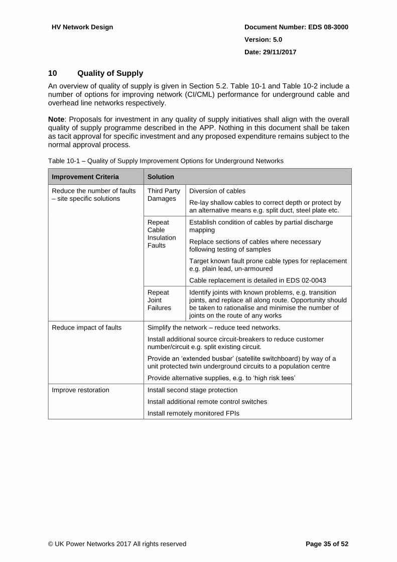
HV Network Design Document Number: EDS 08-3000
Version: 5.0
Date: 29/11/2017
© UK Power Networks 2017 All rights reserved Page 35 of 52
10 Quality of Supply
An overview of quality of supply is given in Section 5.2. Table 10-1 and Table 10-2 include a number of options for improving network (CI/CML) performance for underground cable and overhead line networks respectively.
Note: Proposals for investment in any quality of supply initiatives shall align with the overall quality of supply programme described in the APP. Nothing in this document shall be taken as tacit approval for specific investment and any proposed expenditure remains subject to the normal approval process.
Table 10-1 – Quality of Supply Improvement Options for Underground Networks
Improvement Criteria Solution
Reduce the number of faults – site specific solutions
Third Party Damages
Diversion of cables
Re-lay shallow cables to correct depth or protect by an alternative means e.g. split duct, steel plate etc.
Repeat Cable Insulation Faults
Establish condition of cables by partial discharge mapping
Replace sections of cables where necessary following testing of samples
Target known fault prone cable types for replacement e.g. plain lead, un-armoured
Cable replacement is detailed in EDS 02-0043
Repeat Joint Failures
Identify joints with known problems, e.g. transition joints, and replace all along route. Opportunity should be taken to rationalise and minimise the number of joints on the route of any works
Reduce impact of faults Simplify the network – reduce teed networks.
Install additional source circuit-breakers to reduce customer number/circuit e.g. split existing circuit.
Provide an ‘extended busbar’ (satellite switchboard) by way of a unit protected twin underground circuits to a population centre
Provide alternative supplies, e.g. to ‘high risk tees’
Improve restoration Install second stage protection
Install additional remote control switches
Install remotely monitored FPIs
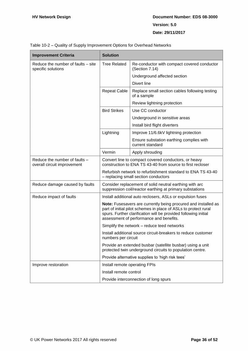
HV Network Design Document Number: EDS 08-3000
Version: 5.0
Date: 29/11/2017
© UK Power Networks 2017 All rights reserved Page 36 of 52
Table 10-2 – Quality of Supply Improvement Options for Overhead Networks
Improvement Criteria Solution
Reduce the number of faults – site specific solutions
Tree Related Re-conductor with compact covered conductor (Section 7.14)
Underground affected section
Divert line
Repeat Cable Replace small section cables following testing of a sample
Review lightning protection
Bird Strikes Use CC conductor
Underground in sensitive areas
Install bird flight diverters
Lightning Improve 11/6.6kV lightning protection
Ensure substation earthing complies with current standard
Vermin Apply shrouding
Reduce the number of faults – overall circuit improvement
Convert line to compact covered conductors, or heavy construction to ENA TS 43-40 from source to first recloser
Refurbish network to refurbishment standard to ENA TS 43-40 – replacing small section conductors
Reduce damage caused by faults Consider replacement of solid neutral earthing with arc suppression coil/reactor earthing at primary substations
Reduce impact of faults Install additional auto reclosers, ASLs or expulsion fuses
Note: Fusesavers are currently being procured and installed as part of initial pilot schemes in place of ASLs to protect rural spurs. Further clarification will be provided following initial assessment of performance and benefits.
Simplify the network – reduce teed networks
Install additional source circuit-breakers to reduce customer numbers per circuit
Provide an extended busbar (satellite busbar) using a unit protected twin underground circuits to population centre.
Provide alternative supplies to ‘high risk tees’
Improve restoration Install remote operating FPIs
Install remote control
Provide interconnection of long spurs
HV Network Design Document Number: EDS 08-3000
Version: 5.0
Date: 29/11/2017
© UK Power Networks 2017 All rights reserved Page 37 of 52
11 Network Resilience
11.1 Overview
Network resilience takes into account the ability to withstand major weather related events. Widespread extreme weather conditions have the potential to cause extensive damage to overhead networks, and in particular the case of snow or flooding making access to sites for repairs difficult with outages of 48 hours or more to large numbers of customers. The impact of severe weather events on customers can be reduced if supplies to centres of population can be maintained. In addition to maintaining supplies to customers within these areas, this will accelerate outage restoration for more remote customers.
A high proportion of larger areas with high population density is already supplied from underground networks with a primary substation in the immediate locality and therefore has the necessary resilience to avoid major disruption of supplies during severe weather events. Investigation of supplies to all larger communities is therefore required, firstly to establish those supplied from overhead line networks and secondly to select, in order of population size of community supplied, the overhead lines to be targeted for resilience improvement measures.
Information regarding the number of households within a parish is available from the National Census and as such, each household can be considered as a customer. In most cases, the parish boundaries will include isolated customers and therefore reference has to be made to network records to identify the core of any community that warrants investigation.
To determine which supplies should be considered for resilience work, it is necessary to define a threshold in terms of numbers of customers in any one community. The 2001 census records indicate approximately 420 parishes in the combined EPN/SPN area with more than 1200 households and sampling indicates that approximately 43% of these (181 parishes) are overhead line supplied with no primary substation in the immediate vicinity. It is considered that this would be a manageable number of communities to investigate for resilience improvement and also have a substantial overall effect on network resilience.
When 11/6.6kV overhead line networks are being considered for refurbishment or replacement, sizes of villages supplied from this network shall also be investigated and any community found to have greater than 1200 customers should be reviewed for ‘network resilience’ works.
11.2 Planning Actions to Improve Network Resilience
Rural networks comprise a combination of distributed load made up of farms and small clusters of customers and villages, creating load centres at points within the network and frequently at the tail end of a circuit or spur within the circuit. Urban networks that have been extended in semi-rural areas also create a ‘resilience risk’.
11.2.1 Distributed Networks
Rural circuits that only supply small communities without any load centres should be refurbished to ENA TS 43-40 with the addition of ‘tool-box’ solutions (Table 10-2) to address identified risks. Where the circuit supplies more than 1200 customers, the circuit as far as the first auto-recloser should be re-conductored with CC conductor that is suitably sized to meet first fault outage loading conditions and to maintain voltage limits within ± 6%.

HV Network Design Document Number: EDS 08-3000
Version: 5.0
Date: 29/11/2017
© UK Power Networks 2017 All rights reserved Page 38 of 52
11.2.2 Intermediate and Tail End Load Centres
In many cases, a village will be supplied by more than two circuits. In the long term, one in-feed should be developed as the ‘resilient circuit’ and reinforced to a minimum of 120mm2 CC conductor. As an alternative, an underground in-feed may be more appropriate, this could provide the opportunity to replace small-section underground circuits. This circuit shall be capable of supporting the maximum demand of the village and maintaining voltage limits within ± 6%.
The network within the village should be reviewed to create a largely ring main – tee – ring main network (where practicable) that enables the village to be supplied from the ‘resilient circuit’.
The location of downstream protective devices shall be reviewed in association with reconfiguration of the network.
It should be noted that the above refers to resilience. Network loadings and alternative supplies should be considered on a separate basis.
11.3 Process for Network Resilience Improvement
Stage 1 – Determine the improvements necessary to provide the required level of resilience to the identified communities, taking into account the impacts of these proposals on adjacent circuits.
Stage 2 – Review the proposed network in terms of quality of supply improvement. The existing fault history is to be examined and the network improved through the application of ‘tool-box’ solutions (Table 10-2). The optimum location of protection devices is to be decided based on network studies using the approved network modelling tool.
Note: Proposals for investment in any of these initiatives shall align with the relevant programme in the current version of the APP. Nothing in this document shall be taken as tacit approval for specific investment and any proposed expenditure remains subject to the normal approvals process.
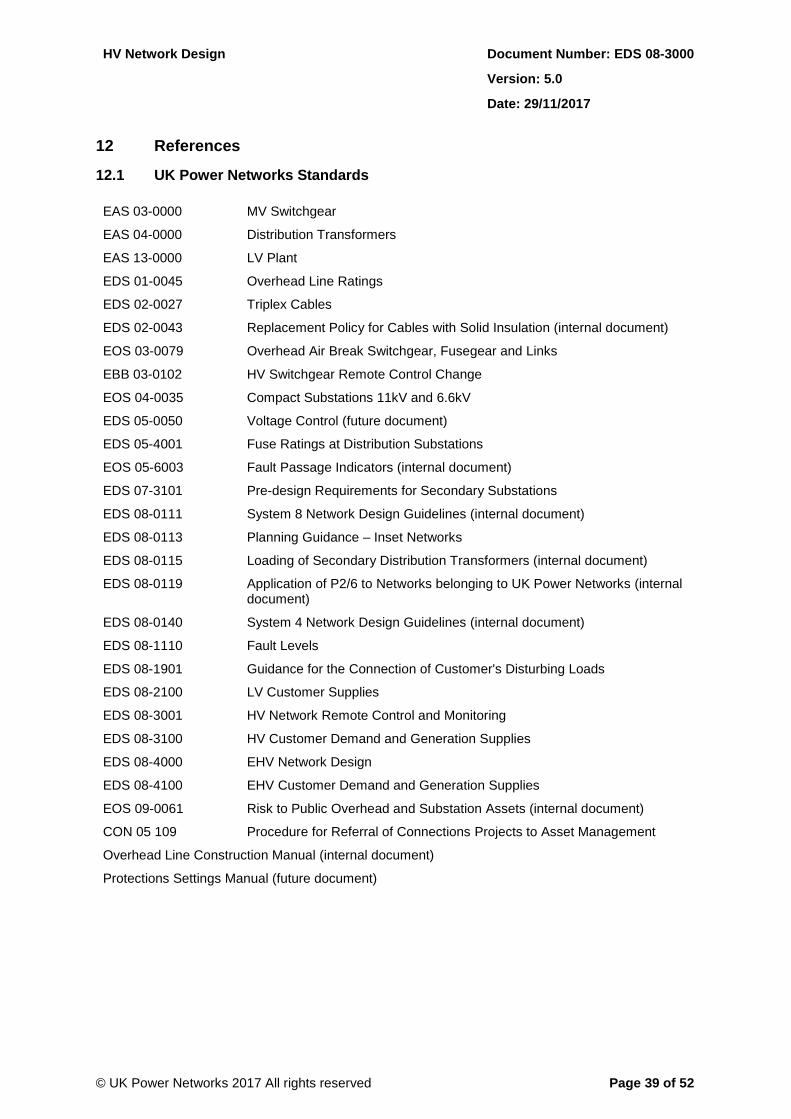
HV Network Design Document Number: EDS 08-3000
Version: 5.0
Date: 29/11/2017
© UK Power Networks 2017 All rights reserved Page 39 of 52
12 References
12.1 UK Power Networks Standards
EAS 03-0000 MV Switchgear
EAS 04-0000 Distribution Transformers
EAS 13-0000 LV Plant
EDS 01-0045 Overhead Line Ratings
EDS 02-0027 Triplex Cables
EDS 02-0043 Replacement Policy for Cables with Solid Insulation (internal document)
EOS 03-0079 Overhead Air Break Switchgear, Fusegear and Links
EBB 03-0102 HV Switchgear Remote Control Change
EOS 04-0035 Compact Substations 11kV and 6.6kV
EDS 05-0050 Voltage Control (future document)
EDS 05-4001 Fuse Ratings at Distribution Substations
EOS 05-6003 Fault Passage Indicators (internal document)
EDS 07-3101 Pre-design Requirements for Secondary Substations
EDS 08-0111 System 8 Network Design Guidelines (internal document)
EDS 08-0113 Planning Guidance – Inset Networks
EDS 08-0115 Loading of Secondary Distribution Transformers (internal document)
EDS 08-0119 Application of P2/6 to Networks belonging to UK Power Networks (internal document)
EDS 08-0140 System 4 Network Design Guidelines (internal document)
EDS 08-1110 Fault Levels
EDS 08-1901 Guidance for the Connection of Customer's Disturbing Loads
EDS 08-2100 LV Customer Supplies
EDS 08-3001 HV Network Remote Control and Monitoring
EDS 08-3100 HV Customer Demand and Generation Supplies
EDS 08-4000 EHV Network Design
EDS 08-4100 EHV Customer Demand and Generation Supplies
EOS 09-0061 Risk to Public Overhead and Substation Assets (internal document)
CON 05 109 Procedure for Referral of Connections Projects to Asset Management
Overhead Line Construction Manual (internal document)
Protections Settings Manual (future document)
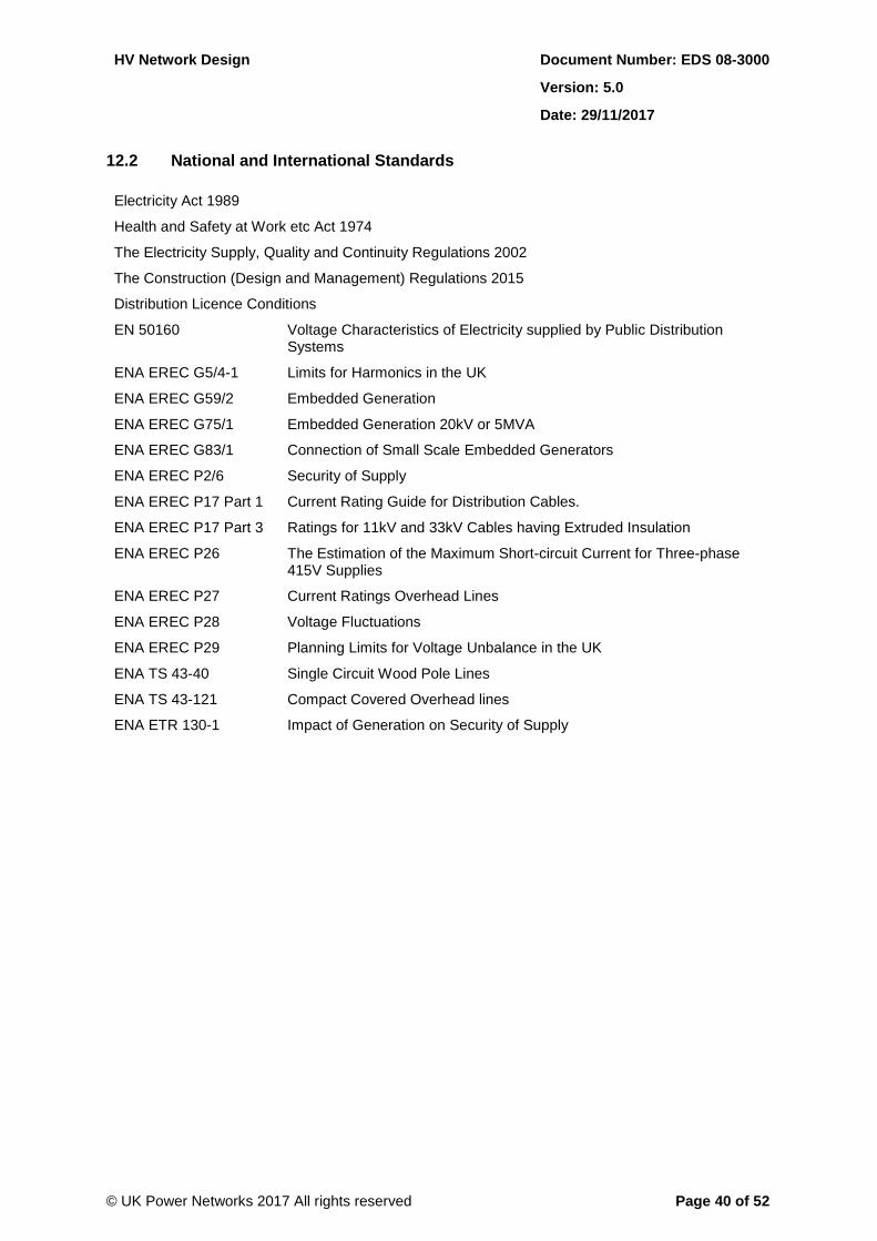
HV Network Design Document Number: EDS 08-3000
Version: 5.0
Date: 29/11/2017
© UK Power Networks 2017 All rights reserved Page 40 of 52
12.2 National and International Standards
Electricity Act 1989
Health and Safety at Work etc Act 1974
The Electricity Supply, Quality and Continuity Regulations 2002
The Construction (Design and Management) Regulations 2015
Distribution Licence Conditions
EN 50160 Voltage Characteristics of Electricity supplied by Public Distribution Systems
ENA EREC G5/4-1 Limits for Harmonics in the UK
ENA EREC G59/2 Embedded Generation
ENA EREC G75/1 Embedded Generation 20kV or 5MVA
ENA EREC G83/1 Connection of Small Scale Embedded Generators
ENA EREC P2/6 Security of Supply
ENA EREC P17 Part 1 Current Rating Guide for Distribution Cables.
ENA EREC P17 Part 3 Ratings for 11kV and 33kV Cables having Extruded Insulation
ENA EREC P26 The Estimation of the Maximum Short-circuit Current for Three-phase 415V Supplies
ENA EREC P27 Current Ratings Overhead Lines
ENA EREC P28 Voltage Fluctuations
ENA EREC P29 Planning Limits for Voltage Unbalance in the UK
ENA TS 43-40 Single Circuit Wood Pole Lines
ENA TS 43-121 Compact Covered Overhead lines
ENA ETR 130-1 Impact of Generation on Security of Supply
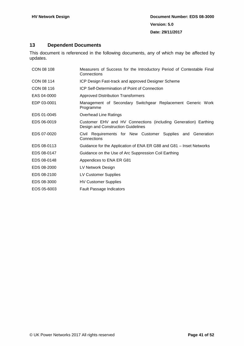
HV Network Design Document Number: EDS 08-3000
Version: 5.0
Date: 29/11/2017
© UK Power Networks 2017 All rights reserved Page 41 of 52
13 Dependent Documents
This document is referenced in the following documents, any of which may be affected by updates.
CON 08 108 Measurers of Success for the Introductory Period of Contestable Final Connections
CON 08 114 ICP Design Fast-track and approved Designer Scheme
CON 08 116 ICP Self-Determination of Point of Connection
EAS 04-0000 Approved Distribution Transformers
EDP 03-0001 Management of Secondary Switchgear Replacement Generic Work Programme
EDS 01-0045 Overhead Line Ratings
EDS 06-0019 Customer EHV and HV Connections (including Generation) Earthing Design and Construction Guidelines
EDS 07-0020 Civil Requirements for New Customer Supplies and Generation Connections
EDS 08-0113 Guidance for the Application of ENA ER G88 and G81 – Inset Networks
EDS 08-0147 Guidance on the Use of Arc Suppression Coil Earthing
EDS 08-0148 Appendices to ENA ER G81
EDS 08-2000 LV Network Design
EDS 08-2100 LV Customer Supplies
EDS 08-3000 HV Customer Supplies
EOS 05-6003 Fault Passage Indicators
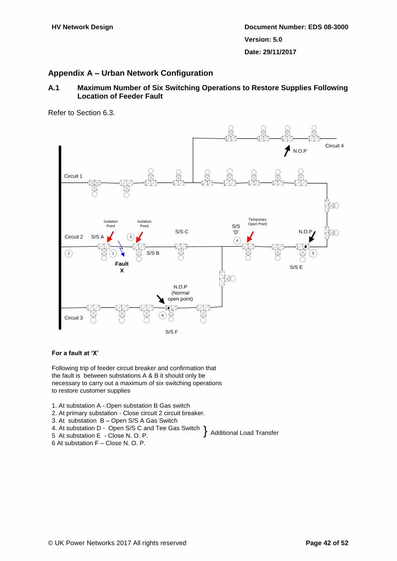
HV Network Design Document Number: EDS 08-3000
Version: 5.0
Date: 29/11/2017
© UK Power Networks 2017 All rights reserved Page 42 of 52
Appendix A – Urban Network Configuration
A.1 Maximum Number of Six Switching Operations to Restore Supplies Following Location of Feeder Fault
Refer to Section 6.3.
Circuit 4
S/S A
S/S B
Fault
X
Circuit 1
Circuit 2S/S C
S/S E
Circuit 3
N.O.P
(Normal
open point)
S/S F
Temporary
Open PointIsolation
Point
Isolation
Point S/S
‘D’ N.O.P
N.O.P
2
3
5
4
1
For a fault at ‘X’
Following trip of feeder circuit breaker and confirmation that
the fault is between substations A & B it should only be
necessary to carry out a maximum of six switching operations
to restore customer supplies
1. At substation A -.Open substation B Gas switch
2. At primary substation - Close circuit 2 circuit breaker.
3. At substation B – Open S/S A Gas Switch
4. At substation D - Open S/S C and Tee Gas Switch
5 At substation E - Close N. O. P.
6 At substation F – Close N. O. P.
} Additional Load Transfer
6
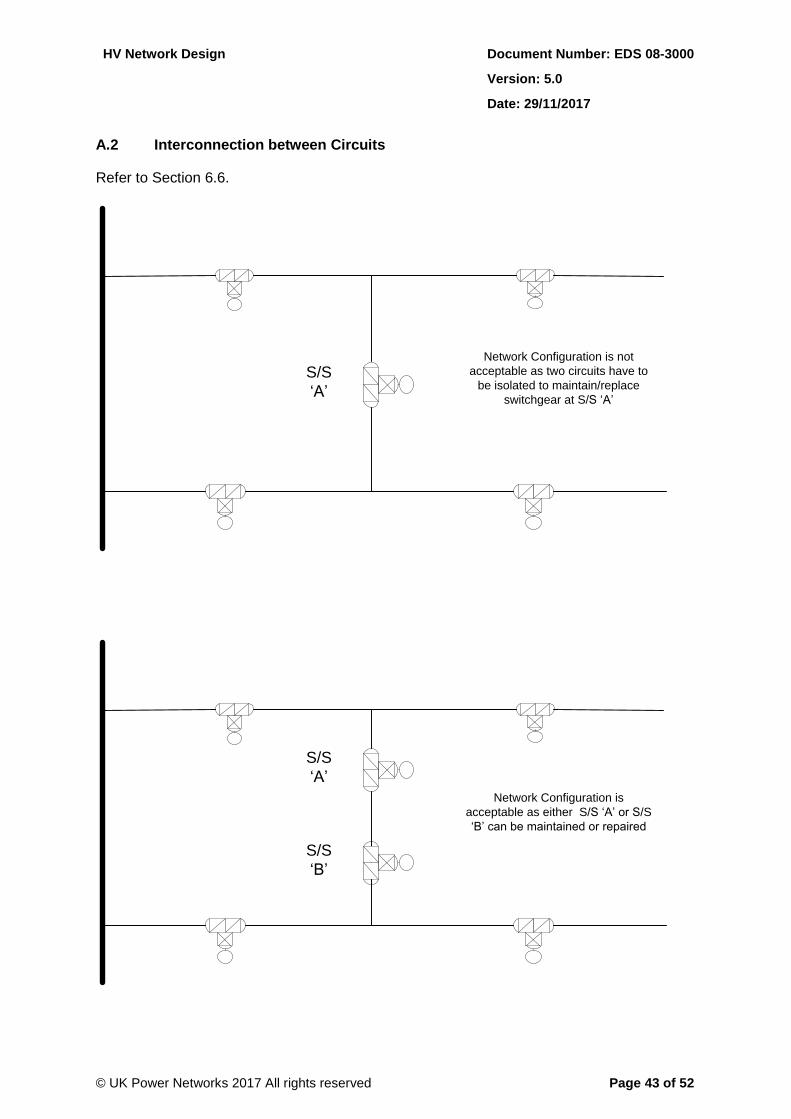
HV Network Design Document Number: EDS 08-3000
Version: 5.0
Date: 29/11/2017
© UK Power Networks 2017 All rights reserved Page 43 of 52
A.2 Interconnection between Circuits
Refer to Section 6.6.
Network Configuration is not
acceptable as two circuits have to
be isolated to maintain/replace
switchgear at S/S ‘A’
S/S
‘A’
Network Configuration is
acceptable as either S/S ‘A’ or S/S
‘B’ can be maintained or repaired
S/S
‘A’
S/S
‘B’
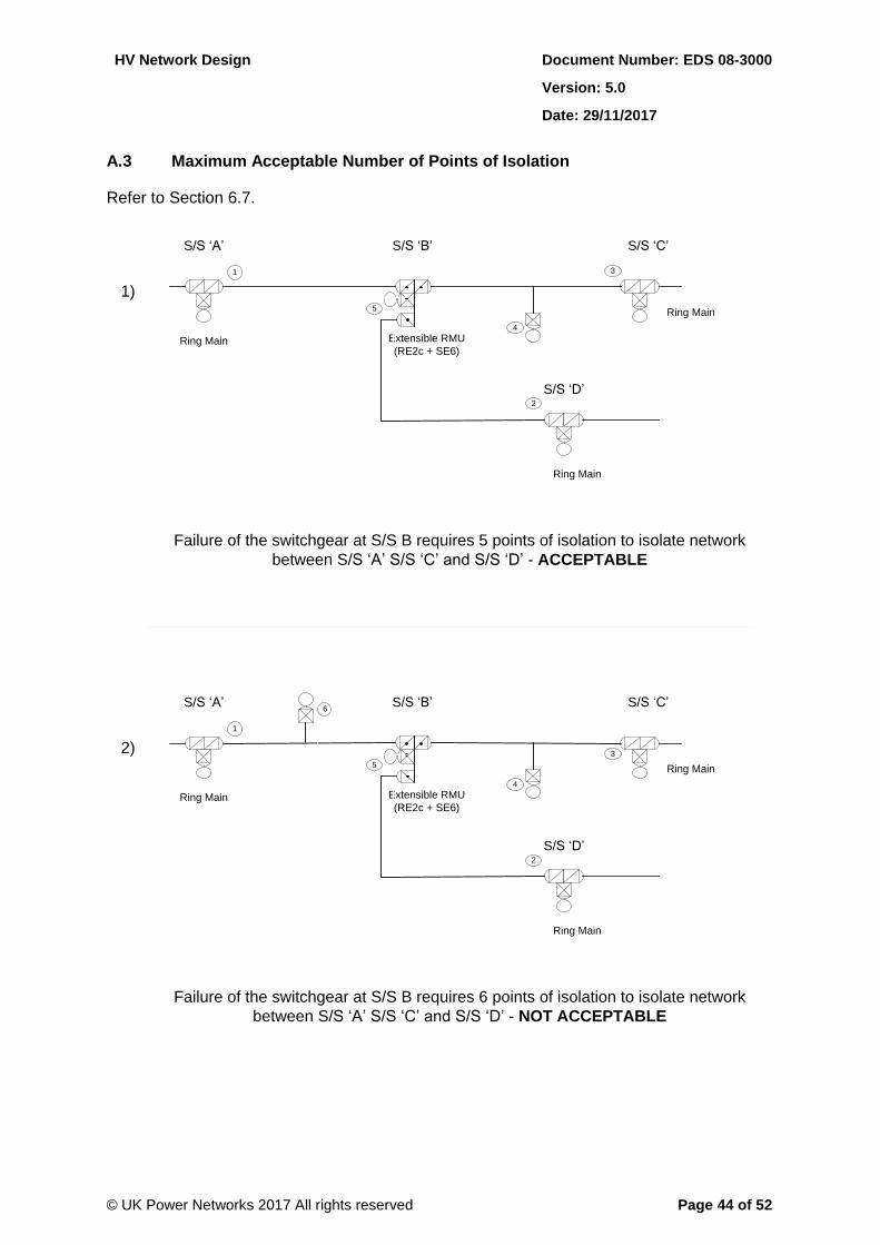
HV Network Design Document Number: EDS 08-3000
Version: 5.0
Date: 29/11/2017
© UK Power Networks 2017 All rights reserved Page 44 of 52
A.3 Maximum Acceptable Number of Points of Isolation
Refer to Section 6.7.
1)1)
Extensible RMU
(RE2c + SE6)
Ring Main
Ring Main
Ring Main
S/S ‘A’ S/S ‘B’ S/S ‘C’
S/S ‘D’
3
5
2
4
1
Failure of the switchgear at S/S B requires 5 points of isolation to isolate network
between S/S ‘A’ S/S ‘C’ and S/S ‘D’ - ACCEPTABLE
2)2)
Extensible RMU
(RE2c + SE6)
Ring Main
Ring Main
Ring Main
S/S ‘A’ S/S ‘B’ S/S ‘C’
S/S ‘D’
3
5
2
4
1
Failure of the switchgear at S/S B requires 6 points of isolation to isolate network
between S/S ‘A’ S/S ‘C’ and S/S ‘D’ - NOT ACCEPTABLE
6
6

HV Network Design Document Number: EDS 08-3000
Version: 5.0
Date: 29/11/2017
© UK Power Networks 2017 All rights reserved Page 45 of 52
Appendix B – Part Completed Network
Refer to Section 8.8.
Requires commitment from developer at start of planning procedure to ensure the final section of network is installed and P2/6 compliance is restored.
Completed area of
development
Key
Site Boundary
New Network Completed
Existing Network
Proposed Network to be
installed
Incomplete area of
development
315
315
500
315
315
Network temporarily non-
compliant with P2/6
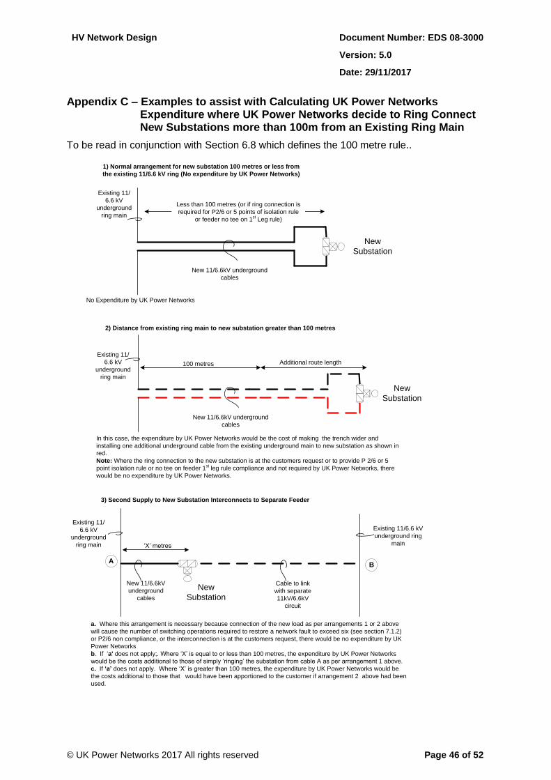
HV Network Design Document Number: EDS 08-3000
Version: 5.0
Date: 29/11/2017
© UK Power Networks 2017 All rights reserved Page 46 of 52
Appendix C – Examples to assist with Calculating UK Power Networks Expenditure where UK Power Networks decide to Ring Connect New Substations more than 100m from an Existing Ring Main
To be read in conjunction with Section 6.8 which defines the 100 metre rule..
Existing 11/
6.6 kV
underground
ring main
New
Substation
Less than 100 metres (or if ring connection is
required for P2/6 or 5 points of isolation rule
or feeder no tee on 1st Leg rule)
New 11/6.6kV underground
cables
1) Normal arrangement for new substation 100 metres or less from
the existing 11/6.6 kV ring (No expenditure by UK Power Networks)
2) Distance from existing ring main to new substation greater than 100 metres
Existing 11/
6.6 kV
underground
ring main
No Expenditure by UK Power Networks
Existing 11/
6.6 kV
underground
ring main
New
Substation
New 11/6.6kV underground
cables
100 metres Additional route length
In this case, the expenditure by UK Power Networks would be the cost of making the trench wider and
installing one additional underground cable from the existing underground main to new substation as shown in
red.
Note: Where the ring connection to the new substation is at the customers request or to provide P 2/6 or 5
point isolation rule or no tee on feeder 1st leg rule compliance and not required by UK Power Networks, there
would be no expenditure by UK Power Networks.
3) Second Supply to New Substation Interconnects to Separate Feeder
New
Substation
a. Where this arrangement is necessary because connection of the new load as per arrangements 1 or 2 above
will cause the number of switching operations required to restore a network fault to exceed six (see section 7.1.2)
or P2/6 non compliance, or the interconnection is at the customers request, there would be no expenditure by UK
Power Networks
b. If ‘a' does not apply;. Where ‘X’ is equal to or less than 100 metres, the expenditure by UK Power Networks
would be the costs additional to those of simply ‘ringing’ the substation from cable A as per arrangement 1 above.
c. If ‘a’ does not apply. Where ‘X’ is greater than 100 metres, the expenditure by UK Power Networks would be
the costs additional to those that would have been apportioned to the customer if arrangement 2 above had been
used.
A
Existing 11/6.6 kV
underground ring
main
B
New 11/6.6kV
underground
cables
Cable to link
with separate
11kV/6.6kV
circuit
‘X’ metres
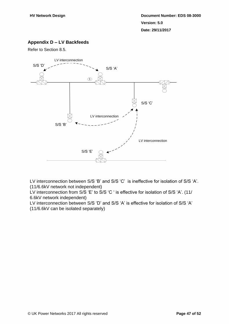
HV Network Design Document Number: EDS 08-3000
Version: 5.0
Date: 29/11/2017
© UK Power Networks 2017 All rights reserved Page 47 of 52
Appendix D – LV Backfeeds
Refer to Section 8.5.
LV interconnection between S/S ‘B’ and S/S ‘C’ is ineffective for isolation of S/S ‘A’.
(11/6.6kV network not independent)
LV interconnection from S/S ‘E’ to S/S ‘C ‘ is effective for isolation of S/S ‘A’. (11/
6.6kV network independent)
LV interconnection between S/S ‘D’ and S/S ‘A’ is effective for isolation of S/S ‘A’
(11/6.6kV can be isolated separately)
S/S ‘A’
S/S ‘B’
S/S ‘C’
5
LV interconnection
S/S ‘E’
S/S ‘D’
LV interconnection
LV interconnection
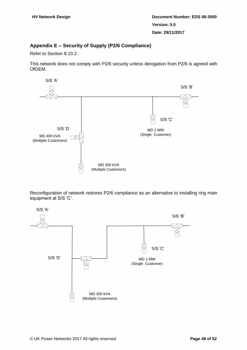
HV Network Design Document Number: EDS 08-3000
Version: 5.0
Date: 29/11/2017
© UK Power Networks 2017 All rights reserved Page 48 of 52
Appendix E – Security of Supply (P2/6 Compliance)
Refer to Section 8.10.2.
This network does not comply with P2/6 security unless derogation from P2/6 is agreed with OfGEM.
S/S ‘A’
S/S ‘C’
S/S ‘D’
S/S ‘B’
MD 400 kVA
(Multiple Customers)
MD 300 kVA
(Multiple Customers)
MD 1 MW
(Single Customer)
Reconfiguration of network restores P2/6 compliance as an alternative to installing ring main equipment at S/S ‘C’.
S/S ‘A’
S/S ‘C’
S/S ‘D’
S/S ‘B’
MD 300 kVA
(Multiple Customers)
MD 1 MW
(Single Customer)
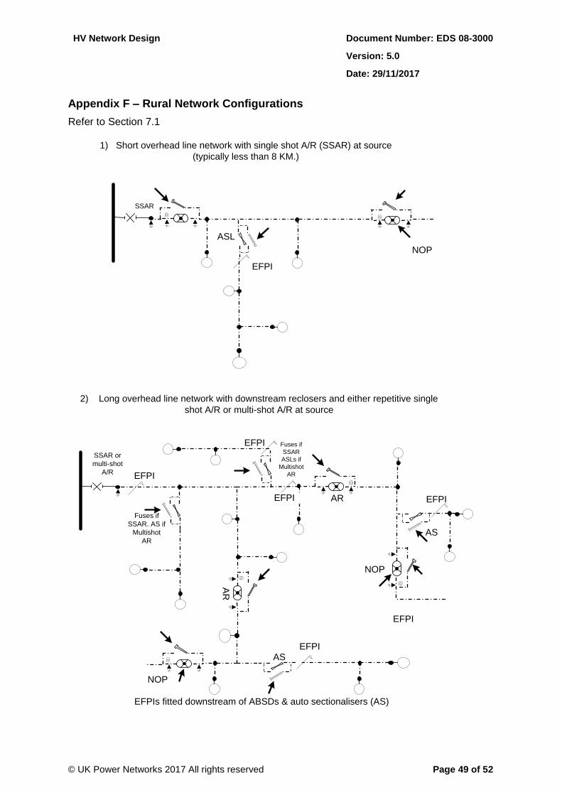
HV Network Design Document Number: EDS 08-3000
Version: 5.0
Date: 29/11/2017
© UK Power Networks 2017 All rights reserved Page 49 of 52
Appendix F – Rural Network Configurations
Refer to Section 7.1
Fuses if
SSAR
ASLs if
Multishot
AR
2) Long overhead line network with downstream reclosers and either repetitive single
shot A/R or multi-shot A/R at source
1) Short overhead line network with single shot A/R (SSAR) at source
(typically less than 8 KM.)
NOP
SSAR
ASL
EFPI
EFPI
NOP
SSAR or
multi-shot
A/R
EFPI
AR
AS
AR EFPIEFPI
EFPI
EFPI
AS
NOP
Fuses if
SSAR. AS if
Multishot
AR
EFPIs fitted downstream of ABSDs & auto sectionalisers (AS)
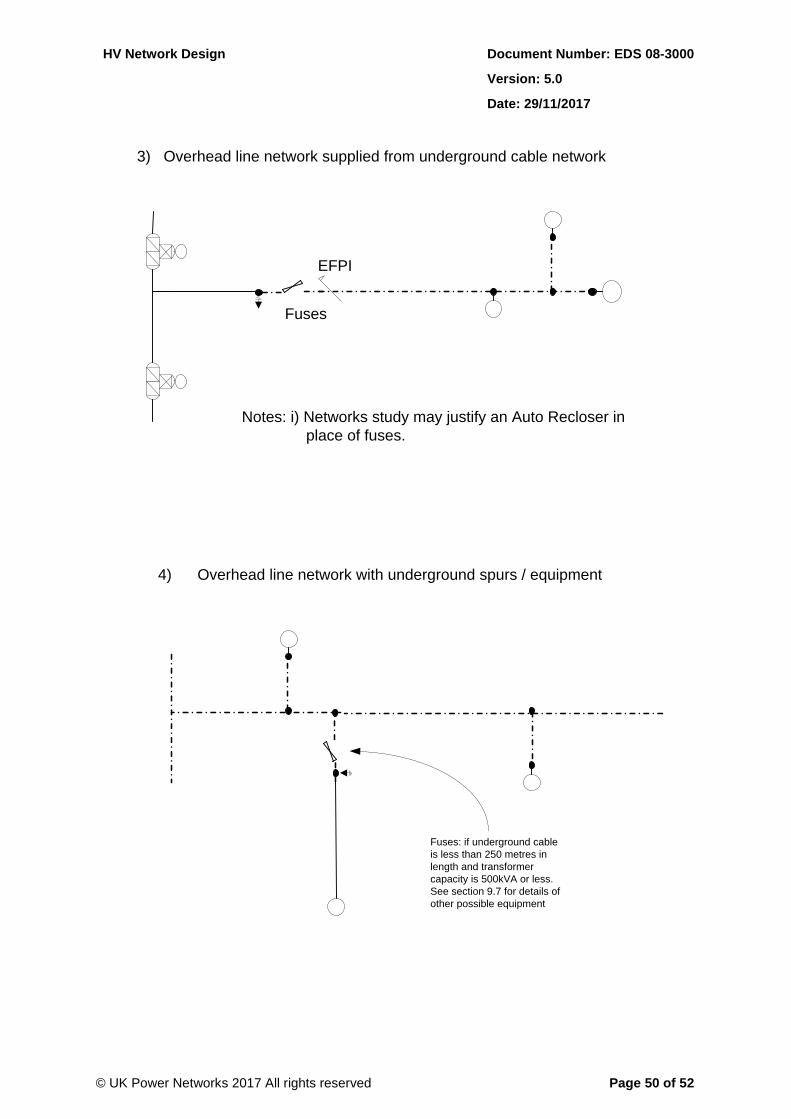
HV Network Design Document Number: EDS 08-3000
Version: 5.0
Date: 29/11/2017
© UK Power Networks 2017 All rights reserved Page 50 of 52
3) Overhead line network supplied from underground cable network
4) Overhead line network with underground spurs / equipment
Fuses
EFPI
Notes: i) Networks study may justify an Auto Recloser in
place of fuses.
Fuses: if underground cable
is less than 250 metres in
length and transformer
capacity is 500kVA or less.
See section 9.7 for details of
other possible equipment
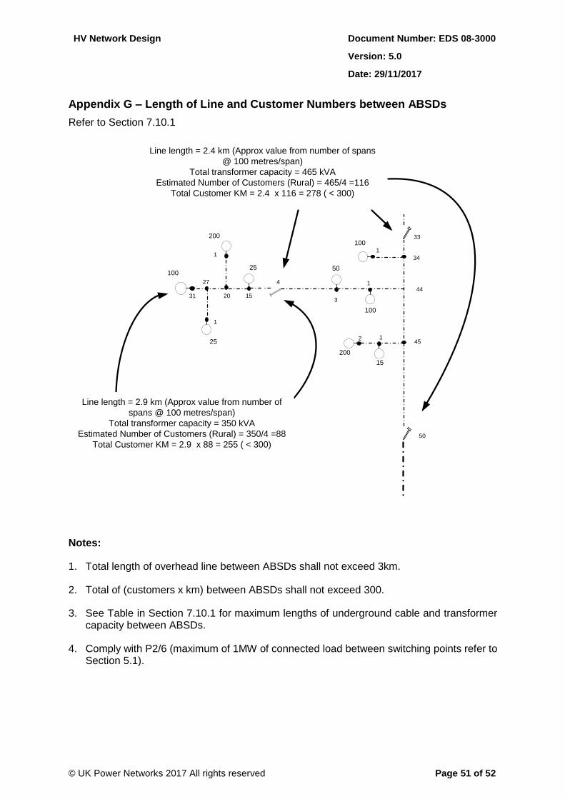
HV Network Design Document Number: EDS 08-3000
Version: 5.0
Date: 29/11/2017
© UK Power Networks 2017 All rights reserved Page 51 of 52
Appendix G – Length of Line and Customer Numbers between ABSDs
Refer to Section 7.10.1
3
25
25 50
200
100
1
100
100
15
4
31 20
1
33
50
2
1
34
44
45
Line length = 2.4 km (Approx value from number of spans
@ 100 metres/span)
Total transformer capacity = 465 kVA
Estimated Number of Customers (Rural) = 465/4 =116
Total Customer KM = 2.4 x 116 = 278 ( < 300)
1
15
1
200
Line length = 2.9 km (Approx value from number of
spans @ 100 metres/span)
Total transformer capacity = 350 kVA
Estimated Number of Customers (Rural) = 350/4 =88
Total Customer KM = 2.9 x 88 = 255 ( < 300)
27
Notes:
1. Total length of overhead line between ABSDs shall not exceed 3km.
2. Total of (customers x km) between ABSDs shall not exceed 300.
3. See Table in Section 7.10.1 for maximum lengths of underground cable and transformer capacity between ABSDs.
4. Comply with P2/6 (maximum of 1MW of connected load between switching points refer to Section 5.1).
HV Network Design Document Number: EDS 08-3000
Version: 5.0
Date: 29/11/2017
© UK Power Networks 2017 All rights reserved Page 52 of 52
Appendix H – Background on Overhead Line Restrictions
H.1 Ferro-Resonance
Ferro-resonance in the context of this standard is caused by the series combination of the iron cored inductance of an unloaded or very lightly loaded transformer with the phase-to-ground capacitance of an underground cable.
If a cable and transformer combination are disconnected or connected using an un-ganged isolator, un-ganged fusegear or live line techniques (including live line taps or jumper cutting) Ferro-resonance can occur during the period that the combination is only partially disconnected.
During Ferro-resonance a voltage higher than normal is present on a disconnected phase which is energised from a connected phase through the transformer primary winding. A series combination of iron cored inductance and capacitance does not have a fixed resonant frequency because the inductance of an iron cored device is non-linear with a pronounced knee point as voltage increases. Ferro-resonant circuits are self-tuning and the tendency for the circuit to adopt a Ferro-resonant state cannot be prevented by limiting cable lengths.
Ferro-resonance can be prevented by ensuring that sufficient resistive load is present to damp the resonance. Surge arresters when subject to overvoltage reduce their resistance and can act to damp Ferro-resonance however they only have a limited energy capacity for this type of duty. Practical experience from the EPN network has demonstrated that a 250m cable length limit is sufficient to limit the energy dissipated in the surge arrester such that surge arrester failures from this cause are rare.
Refer to EOS 03-0079 for further information.
H.2 Voltage Unbalance
ENA EREC P29 sets the limit for unbalanced voltage defined as a negative phase sequence voltage limit of 1.3% for systems with a nominal voltage below 33kV. Unbalanced charging currents associated with underground cable on single-phase spurs will give rise to negative phase sequence voltages. Such negative phase sequence voltages will be proportional to both the length of cable connected to the spur and the source impedance at the point of connection of the spur to the main line. However the load connected is more likely to be the dominant factor when considering negative phase sequence.
For the voltage unbalance calculation, refer to ENA EREC P29.
H.3 Neutral Voltage Displacement and Capacity of ASC earthed systems
The principle behind an ASC earthed system is that under fault conditions with one phase connected to earth at the point of fault the capacitive charging current of the other two phases is provided by the reactance of the ASC. To do this the ASC has to be tuned such that its inductive reactance matches the capacitive reactance of all the system. In this condition it is tuned to resonance at 50Hz.
Refer to EDS 08-0147 for more information.